

Page 1
DAT-Link/DAT-Link
User's Manual
Townshend Computer Tools, Inc.
10 Ontario West, Suite 502
Montreal, Quebec, Canada
H2X 1Y6
514-289-9123
Revision 2.28
June 13, 1997
+
Page 2

c
Copyright 1991-1995 Townshend Computer Tools, Inc.
DAT-Link,DAT-Link
Tools
DEC, DECstation, and Ultrix are trademarks of Digital Equipment Corporation.
RISC/6000 and AIX are trademarks of IBM.
Sun-3, Sun-4, SPARC, SunOS, and Sun Workstation are all registered trademarks
of Sun Microsystems, Incorporated.
UNIX
is a registered trademark of AT&T Bell Laboratories.
+, and NetAudio are trademarks of Townshend Computer
Page 3
DAT-Link/DAT-Link
User's Manual
Ariel Corporation
433 River Road
Highland Park, NJ
908-249-2900
Revision 2.28
June 13, 1997
+
Page 4
c
Copyright 1991-1995 Townshend Computer Tools, Inc.
DAT-Link,DAT-Link
Tools
DEC, DECstation, and Ultrix are trademarks of Digital Equipment Corporation.
RISC/6000 and AIX are trademarks of IBM.
Sun-3, Sun-4, SPARC, SunOS, and Sun Workstation are all registered trademarks
of Sun Microsystems, Incorporated.
UNIX
is a registered trademark of AT&T Bell Laboratories.
+, and NetAudio are trademarks of Townshend Computer
Page 5
Contents
1 Introduction 7
1.1 About This Manual
1.2 Getting Help
2 Installation 9
2.1 What Comes with the
2.2 What You Need to Provide
2.3 Hardware Connection Summary
2.4 Machine Sp ecic Instructions
2.4.1 SUN Microsystems
2.4.2 Digital Equipment Corporation, DECstation
2.4.3 Digital Equipment Corporation, DECstation
2.4.4 Hewlett-Packard
2.4.5 IBM Risc Systems/6000
2.4.6 Solbourne
2.4.7 Sony NEWS Workstations
2.4.8 Silicon Graphics
2.4.9 IBM PC and Compatibles
2.4.10 NeXT
2.4.11 Other UNIX-Based Computers
2.5 Connecting to a Digital Audio Device
2.6 Software Installation
2.6.1 Installation from DATTape
2.6.2 Conguring the Installation
2.6.3 Installation from Cartridge or DDS DATTape
2.6.4 DOS Software Installation
2.7 Testing the DAT-Link
2.7.1 Testing the Connection to the Computer
2.7.2 Testing the Infrared Remote Control
2.7.3 Testing the Digital Audio Connections
: : : : : : : : : : : : : : : : : : : : : : : : : : : : : : :
: : : : : : : : : : : : : : : : : : : : : : : : : : : : : : :
: : : : : : : : : : : : : : : : : : : : : : : : : : :
DAT-Link
: : : : : : : : : : : : : : : : : : : : : : : :
: : : : : : : : : : : : : : : : : : : : : : : : :
: : : : : : : : : : : : : : : : : : : : : : : : : : : : :
: : : : : : : : : : : : : : : : : : : : : : : : :
: : : : : : : : : : : : : : : : : : : : : : : : : : :
: : : : : : : : : : : : : : : : : : : : : : : : : :
: : : : : : : : : : : : : : : : : : : :
: : : : : : : : : : : : : : : : : : : : : : :
: : : : : : : : : : : : : : : : : : : : :
: : : : : : : : : : : : : : : : : : : : : :
: : : : : : : : :
: : : : : : : : :
: : : : : : : : : : : : : : : : : : : : :
: : : : : : : : : : : : : : : : : : : :
: : : : : : : : : : : : : : : : : : : :
: : : : : : : : : : : : : : : : :
: : : : : : : : : : : : : : : : :
: : : : : : : : : : : : : : : : : : :
: : : : : : : : : : : : : : : : : : :
: : : : : : : :
: : : : : : : : : : : : : : : : : : : :
: : : : : : : : : : : :
: : : : : : : : : : : : : :
: : : : : : : : : : : : :
10
10
11
14
16
18
20
23
25
26
29
32
33
34
35
35
38
39
40
41
41
42
43
8
8
9
9
Page 6
2 CONTENTS
3 NetAudio Server 45
3.1 Starting the Server
3.2 Setting up to Run Client Programs
3.3 Programs that Bypass the Server
3.4 Terminating the Server
4 Command Summary 49
5 Playback Tutorial 51
5.1 Setting up the DAT Machine
5.1.1 Recording onto a DAT
5.1.2 Listening to a File Without Recording
5.2 Running the
5.3 FrontPanel Indications
5.4 Stereo or Mono
5.5 Playing Part of a File
5.6 Repeating a Passage
5.7 Sampling Rates
5.7.1 DAT Sampling Rate
5.7.2 File Sampling Rate
5.8 File Formats
5.9 Playing Multiple Files
5.10 Using Standard Input
5.11 Channel Status and User Bits
5.12 Starting and Stopping the DAT
5.13 Buering of Audio Data
5.14 Customizing the Conguration
naplay
: : : : : : : : : : : : : : : : : : : : : : : : : : : :
: : : : : : : : : : : : : : : : : : :
: : : : : : : : : : : : : : : : : : : :
: : : : : : : : : : : : : : : : : : : : : : : : : :
: : : : : : : : : : : : : : : : : : : : : :
: : : : : : : : : : : : : : : : : : : : : :
: : : : : : : : : : : : :
Program
: : : : : : : : : : : : : : : : : : : : : : : : : : : : : :
: : : : : : : : : : : : : : : : : : : : : : : : : :
: : : : : : : : : : : : : : : : : : : : : : : : : : :
: : : : : : : : : : : : : : : : : : : : : : : : : : : : : :
: : : : : : : : : : : : : : : : : : : : : : : : : : : : : : :
: : : : : : : : : : : : : : : : : : : : : : : : : :
: : : : : : : : : : : : : : : : : : : : : : : : : :
: : : : : : : : : : : : : : : : : : : : : :
: : : : : : : : : : : : : : : : : : : : : : : : :
: : : : : : : : : : : : : : : : : : : : : : :
: : : : : : : : : : : : : : : : : : : : : : : :
: : : : : : : : : : : : : : : : : : : : : :
: : : : : : : : : : : : : : : : : : : : :
: : : : : : : : : : : : : : : : : : : : : : : : :
: : : : : : : : : : : : : : : : : : : : :
46
47
48
48
51
51
52
52
52
53
53
54
54
54
56
56
57
57
58
58
59
59
6 Recording Tutorial 61
6.1 Setting up the DAT Machine
6.1.1 Transferring from Tape to Disk
6.1.2 Transferring from CD to Disk
6.1.3 Making a Live Recording
6.2 Running the
6.3 FrontPanel Indications
6.4 Selecting the Input Source
6.5 Stereo or Mono
6.6 Specifying the Recording Duration
6.7 Sampling Rates
6.7.1 DAT Sampling Rate
6.7.2 File Sampling Rate
6.8 Skipping Silence
6.9 File Formats
6.10 Using Standard Output
6.11 Channel Status and User Bits
narecord
: : : : : : : : : : : : : : : : : : : : : : : : : : : : : : :
Program
: : : : : : : : : : : : : : : : : : : : : : : : : : : : : :
: : : : : : : : : : : : : : : : : : : : : : : : : : : : : :
: : : : : : : : : : : : : : : : : : : : : : : : : : : : :
: : : : : : : : : : : : : : : : : : : : : :
: : : : : : : : : : : : : : : : :
: : : : : : : : : : : : : : : : : :
: : : : : : : : : : : : : : : : : : : :
: : : : : : : : : : : : : : : : : : : :
: : : : : : : : : : : : : : : : : : : : : : : : :
: : : : : : : : : : : : : : : : : : : : : : : :
: : : : : : : : : : : : : : : : : : :
: : : : : : : : : : : : : : : : : : : : : : :
: : : : : : : : : : : : : : : : : : : : : : : :
: : : : : : : : : : : : : : : : : : : : : : : : :
: : : : : : : : : : : : : : : : : : : : : :
61
61
61
62
63
63
63
64
64
64
65
65
65
66
66
67
Page 7

CONTENTS 3
6.12 Starting and Stopping the DAT
6.13 Buering of Audio Data
6.14 Customizing the Conguration
6.15 Speech Segmentation
7 Sampling Rate Conversion 71
7.1 Specications of Some Example Converters
7.2 Changing the Filter Response
7.3 Stopband Attenuation
8 Remote Control 75
8.1 Training the Infrared Controller
8.2 Using the Remote Control
8.3 ES-Bus Remote Control
8.4 Hard-wired Remote Controls
9 Using Multiple DAT-Links 79
9.1 Synchronization
9.1.1 Synchronization with
9.1.2 Synchronization with
9.2 Multiple Unit Recording
9.3 Multiple Unit Playback
: : : : : : : : : : : : : : : : : : : : : : : : : : : : : :
: : : : : : : : : : : : : : : : : : : : : : : : :
: : : : : : : : : : : : : : : : : : : : : : : : : : :
: : : : : : : : : : : : : : : : : : : : : : : : : :
: : : : : : : : : : : : : : : : : : : : : : : : :
: : : : : : : : : : : : : : : : : : : : : : : : :
: : : : : : : : : : : : : : : : : : : : : : : : :
: : : : : : : : : : : : : : : : : : : : :
: : : : : : : : : : : : : : : : : : : : :
: : : : : : : : : : : : : :
: : : : : : : : : : : : : : : : : : : : : :
: : : : : : : : : : : : : : : : : : : : :
: : : : : : : : : : : : : : : : : : : : : : : :
: : : : : : : : : : : : : : : : : : : : : :
DAT-Link
DAT-Link
+Version 1.6
Versions Prior to 1.6
: : : : : : : : :
: : : :
67
68
68
69
72
72
74
75
76
78
78
80
80
82
83
85
10 Utilities 87
10.1 Checking the Software and Hardware Revision Numbers
10.2 Monitoring NetAudio Server Status
10.3 Controlling NetAudio Server Parameters
10.4 Downloading DSP32C Programs
10.5 Checking the DAT-Link's Filters
10.6 Interactive Playback of Multiple Files
11 Third Party Support 97
11.1 User Interfaces
11.1.1 Entropic Research ESPS/
11.1.2 Comdisco Systems SPW
11.2 Development Software
11.2.1 AT&T DSP32C Development System
11.3 Hardware
11.3.1 Ariel Corp's ProPort
11.3.2 TEAC Data DAT Recorders
12 Subroutine Library 115
: : : : : : : : : : : : : : : : : : : : : : : : : : : : : :
: : : : : : : : : : : : : : : : : : : : : : : : : :
: : : : : : : : : : : : : : : : : : : : : : : : : : : : : : : : :
: : : : : : : : : : : : : : : : : : : : : : :
: : : : : : : : : : : : : : : : : : :
: : : : : : : : : : : : : : : :
: : : : : : : : : : : : : : : : : : : :
: : : : : : : : : : : : : : : : : : : :
: : : : : : : : : : : : : : : : :
waves+
: : : : : : : : : : : : : : : : : : : : :
: : : : : : : : : : : : : : : :
: : : : : : : : : : : : :
: : : : : : : : : : : : : : : : : : :
: : : : : : :
87
87
90
92
92
93
97
97
102
103
103
105
105
108
Page 8
4 CONTENTS
A Troublesho oting 119
A.1 No Communications with DAT-Link
A.2 Device Busy Errors
A.3 DAT Distribution Tape Problems
A.4 Problems with Training (rctrain)
B File Formats 123
B.1 Audio Data File Formats
B.1.1 Raw
B.1.2 Swap
B.1.3 Native
B.1.4 AIFF
B.1.5 AIFC
B.1.6 SPW
B.1.7 ESPS
B.1.8 SPPACK
B.1.9 Multi-Channel File Formats
B.2 Segmentation File Format
B.3 Conguration File (.datlinkrc)
B.4 Channel Status & User Bits Files
B.5 Remote Control Files
B.5.1 Format of the Remote Control Files
B.5.2 Editing the Remote Control Descriptions
: : : : : : : : : : : : : : : : : : : : : : : : : : : : : : : :
: : : : : : : : : : : : : : : : : : : : : : : : : : : : : : : :
: : : : : : : : : : : : : : : : : : : : : : : : : : : : : : : :
: : : : : : : : : : : : : : : : : : : : : : : : : : : :
: : : : : : : : : : : : : : : : : : : : : : : :
: : : : : : : : : : : : : : : : : : : : : : : : : : : : : : :
: : : : : : : : : : : : : : : : : : : : : : : : : : : : : : :
: : : : : : : : : : : : : : : : : : : : : : : : : : : : : : :
: : : : : : : : : : : : : : : : : : : : : : : : : : : : : : :
: : : : : : : : : : : : : : : : : : : : : : : : : : : : :
: : : : : : : : : : : : : : : : : : : : : : : :
: : : : : : : : : : : : : : : : : : : : : :
: : : : : : : : : : : : : : : : : : : : : : : : : : :
: : : : : : : : : : : : : : : : : :
: : : : : : : : : : : : : : : : : : : :
: : : : : : : : : : : : : : : : : : : :
: : : : : : : : : : : : : : : : : : :
: : : : : : : : : : : : : : : : : : : :
: : : : : : : : : : : : : :
: : : : : : : : : : :
119
120
120
121
123
123
123
124
124
124
124
124
125
125
126
126
126
127
127
128
C Connectors 131
C.1
DSP-Port
C.1.1 Conguring the
C.2
Sync
D Digital Audio Devices Supported 135
E DIP Switch settings 139
F Known Bugs and Limitations 141
F.1 Limitations
F.2 Bugs
G Reference Manual 145
G.1 User Programs
DLMKRDY
DLMPLAY
DLMREC
NADSPOD
NAGETFILTER
NALOADDSP
NAPLAY
: : : : : : : : : : : : : : : : : : : : : : : : : : : : : : : : :
DSP-Port
: : : : : : : : : : : : : : : : : : : : : : : : : : : : : : : : : : : :
: : : : : : : : : : : : : : : : : : : : : : : : : : : : : : : :
: : : : : : : : : : : : : : : : : : : : : : : : : : : : : : : : : : : :
: : : : : : : : : : : : : : : : : : : : : : : : : : : : : :
: : : : : : : : : : : : : : : : : : : : : : : : : : : : : : : :
: : : : : : : : : : : : : : : : : : : : : : : : : : : : : : : :
: : : : : : : : : : : : : : : : : : : : : : : : : : : : : : : : :
: : : : : : : : : : : : : : : : : : : : : : : : : : : : : : : :
: : : : : : : : : : : : : : : : : : : : : : : : : : : : :
: : : : : : : : : : : : : : : : : : : : : : : : : : : : : :
: : : : : : : : : : : : : : : : : : : : : : : : : : : : : : : : :
: : : : : : : : : : : : : : : : : : : :
131
131
132
141
143
146
146
147
149
151
152
153
154
Page 9
CONTENTS 5
NARECORD
NARECSEG
NASET
NASTATUS
RC
: : : : : : : : : : : : : : : : : : : : : : : : : : : : : : : : : : : : :
RCTRAIN
SV3900
TEACIN
TEACOUT
XNAPLAY
G.3 Subroutine Library
NA DSP
NA EVENT
NA INFO
NA REMOTE
NETAUDIO
NETAUDIO
G.8 Utilities
DLTEST
NAKILLSERVER
NALOOP
NASERVER
NAVERSION
NETAUDIOD
: : : : : : : : : : : : : : : : : : : : : : : : : : : : : : :
: : : : : : : : : : : : : : : : : : : : : : : : : : : : : : :
: : : : : : : : : : : : : : : : : : : : : : : : : : : : : : : : : :
: : : : : : : : : : : : : : : : : : : : : : : : : : : : : : : :
: : : : : : : : : : : : : : : : : : : : : : : : : : : : : : : : :
: : : : : : : : : : : : : : : : : : : : : : : : : : : : : : : : : :
: : : : : : : : : : : : : : : : : : : : : : : : : : : : : : : : : :
: : : : : : : : : : : : : : : : : : : : : : : : : : : : : : : :
: : : : : : : : : : : : : : : : : : : : : : : : : : : : : : : :
: : : : : : : : : : : : : : : : : : : : : : : : : : : : : : : : : :
: : : : : : : : : : : : : : : : : : : : : : : : : : : : : : : :
: : : : : : : : : : : : : : : : : : : : : : : : : : : : : : : : :
: : : : : : : : : : : : : : : : : : : : : : : : : : : : : :
: : : : : : : : : : : : : : : : : : : : : : : : : : : : : : : :
: : : : : : : : : : : : : : : : : : : : : : : : : : : : : : : :
: : : : : : : : : : : : : : : : : : : : : : : : : : : : : : : : : :
: : : : : : : : : : : : : : : : : : : : : : : : : : : : : : : : :
: : : : : : : : : : : : : : : : : : : : : : : : : : : : : : : : :
: : : : : : : : : : : : : : : : : : : : : : : : : : : : : : : :
: : : : : : : : : : : : : : : : : : : : : : : : : : : : : : :
: : : : : : : : : : : : : : : : : : : : : : : : : : : : : : :
: : : : : : : : : : : : : : : : : : : : : : : : : : : :
: : : : : : : : : : : : : : : : : : : : : : : : : : : :
158
161
163
164
165
166
168
170
172
173
173
174
176
178
181
182
186
188
189
191
192
194
195
196
Bibliography 197
Index 197
Page 10

6 CONTENTS
Page 11
Chapter 1
Intro duction
You have just purchased
tions.
DAT-Link
equipment|DAT, CD, MD, DCC< converters, processors, and other devices.
Link
can be used to play back and record sound les from your workstation or as
an instrument in producing audiophile recordings. Here is a sample of some of the
features of
Recording:
The source can be from tape, CD, or live.
Listening:
Remote Control:
Signal Processing:
real-time ltering and sample-rate conversion to and from any user-specied
rate.
Subco de:
Versatility:
face byemulating standard tape drives { no special system software required.
DAT-Link
or slots required in your computer. When you upgrade your computer,
Link
provides a bridge between your computer and high-quality audio
DAT-Link
Direct-to-disk stereo recording limited only by available disk space.
Fast response playback and transfer from disk to tape.
Full channel status and user bit information can be read and written.
Works with most
is a standalone unit connected via SCSI cable { no add-on boards
will stay with you.
DAT-Link
:
Complete remote control of most DAT machines.
Built-in digital signal processor provides software-controlled,
, the ultimate digital audio solution for worksta-
UNIXorDOS
based workstations with a SCSI inter-
DAT-
DAT-
Expandability:
number of channels is limited only by sp eed of host computer and disk drives.
External clo ck input and output for synchronization with other equipment.
Multiple
DAT-Links
can be used for multi-track recording. The
Page 12

8 Introduction
Network Compatible:
vides access to the
work.
In addition to the above,
DSP-Port:
be connected to external equipment for general purpose DSP applications.
Expandability:
up to 2 Mbytes for users that wish to run their own DSP applications on the
DAT-Link
1.1 About This Manual
This manual consists of two main parts, a user's manual and reference material in
the Appendices. The user's manual should be all you need to use the
it describes the installation of the
are used with it.
The reference manual contains copies of the manual pages that are available online
using the
for users that wish to write their own programs using the
existing programs to special situations. File formats are also described in these
Appendices.
This connector allows the
DAT-Link
+.
UNIX
man
The NetAudio software included with the
DAT-Link
DAT-Link
+'s 64 kbytes of fast static RAM can be upgraded to
command. It also provides some more detailed information
's functions from anywhere on a local area net-
+ adds the following features:
DAT-Link
DAT-Link
+'s DSP32C signal processor to
and each of the major programs that
DAT-Link
DAT-Link
DAT-Link
or adapt the
pro-
|
Note that throughout this manual the name
original
to features unique to the
1.2 Getting Help
If you haveany problems installing or using the
DAT-Link
Also, there is an electronic mailing for
new software releases, p otential problems and advice is p osted. You can join the
list by sending e-mail to
where
the single word
DAT-Link
supplier, or you can contact us by electronic mail at
subscribe dl-users NAME
NAME
and to
is your full name (not your e-mail address). A message consisting of
help
DAT-Link
DAT-Link
can also provide additional information on the mail server.
+. The name
+.
DAT-Link
DAT-Link
DAT-Link
DAT-Link
with a message of:
is used to refer to both the
+ is used only to refer
you can contact your
users where information about
.
Page 13
Chapter 2
Installation
2.1 What Comes with the
The box containing the
The
DAT-Link
An external power supply.
The remote transmitter unit.
A SCSI terminator.
A cartridge or DAT tape containing the
This manual.
2.2 What You Need to Provide
AUNIXorDOS
Mbytes of free disk space and additional space for storing audio les. (Audio
les can consume up to 12 Mbytes/minute.)
A SCSI cable for your workstation to connect it to the
describes the type of cable required for dierenttypes of workstations. Cables
can b e ordered from your
A Digital Audio Tape (DAT) machine or other digital audio device with digital
inputs and/or outputs.
DAT-Link
main unit.
based workstation with a SCSI interface with at least 8
should have contained the following items:
DAT-Link
DAT-Link
DAT-Link
supplier.
software.
DAT-Link
. Section 2.4
Cables to connect the digital audio device to the
turers supply these with the DATorCDmachine.
DAT-Link
. Most manufac-
Page 14
10 Installation
2.3 Hardware Connection Summary
The following is a short summary of the steps needed to connect and congure the
DAT-Link
on using the
. Following sections will expand on these steps and provide information
DAT-Link
with specic computers.
1. Set the
Link
is ignored. See the sections below on individual machine types for help in
selecting an unused SCSI ID number for the
select a SCSI ID already in use by a disk or tape drive. Damage to
disk contents or the computer may result!!
2. Set the
the correct setting will b e all switches down. However, check the appropriate
machine instructions in Section 2.4 for the correct setting.
3. Connect the
This cable must b e ordered separately from the
for eachtyp e of computer. See the detailed instructions for each machine type
below for information on the type of cable required. If the
last device on the SCSI bus, connect the provided SCSI terminator between
the cable and the
4. Connect the digital audio device to the
5. Connect the remote transmitter to the
DAT-Link
infrared remote sensor.
6. Connect the external power supply to the
7. Turn on the front panel power switch on the
Playback
LED may or may not turn on depending on whether a valid digital audio
signal is connected to one of the
SCSI ID
. Once the
Options
LED's on the front panel should ash briey then go out. The
switch on the rear panel switch before powering-up the
DAT-Link
switches on the rear of the
DAT-Link
DAT-Link
and p osition it so that it is in the line-of-sight of the DAT machine's
is turned on, the setting of the
DAT-Link.Be careful not to
DAT-Link
SCSI
port to the host computer via a SCSI cable.
DAT-Link
's SCSI connector.
DAT-Link
remote
DAT-Link
DAT-Link
's inputs.
. (See Section 2.5)
connector on the rear of the
's +5V input.
DAT-Link
SCSI ID
. For most computers
since it is dierent
DAT-Link
. The
Record
DAT-
switch
is the
and
Lock
2.4 Machine Specic Instructions
This section explains in detail how to connect the
computers. You need only refer to the section for the computer of interest to install
the
DAT-Link
listed. The underlined entries indicate congurations which we have tested. The
manufacturers indicate that the other listed congurations should be equivalent
and work equally well. Even if your particular conguration is not listed in these
. For each machine, the models and operating systems supported are
DAT-Link
to dierenttypes of
Page 15
2.4 Machine Specic Instructions 11
sections, the
for details.
2.4.1 SUN Microsystems
Manufacturer:
Models:
Operating System:
Cables Required
To connect the SPARCStation with the
high-density 50 pin D connector
on the other end. This may also be called a
available from your SUN hardware supplier or can be ordered from your
supplier.
Choosing a SCSI ID
If you are using the standard software as supplied by SUN, then SCSI ID's 4 and 5
are reserved for tape drives, or devices such as the
a tap e drive connected to your machine, check its SCSI ID setting which should
be either 4 or 5. You can then use the other number for the
ID's are already b eing used, or if you wish to install multiple
then a custom
administrator. Arbitrary SCSI ID's can then be chosen in the range 0 to 6.
DAT-Link
SPARCStation 1, 1+,2, IPC, IPX, SLC, ELC, 10, 4/470,LX
UNIX
will probably work ne|consult your
SUN Microsystems
SunOS 4.1, 4.1.1, 4.1.2, 4.1.3; Solaris 2.0, 2.1, 2.2, 2.3, 2.4
DAT-Link
on one end and a
SCSI-1 to SCSI-2
kernel must be built for the machine | a job for a system
you will require a cable with a
50 pin Centronics typeconnector
DAT-Link
DAT-Link
cable. It should be
. If you already have
DAT-Link
DAT-Link
supplier
DAT-Link
. If both
devices,
1
The SCSI ID's of all devices connected, including the
by halting the computer and using the
system boot prompt, \>". See the
plied with your workstation for details on halting and rebooting the computer.
Under Solaris 2.x, the
addresses (target ID's) of the connected devices.
Connecting the
The next step is to connect the
unterminate the SCSI bus temp orarily, it is recommended that you shut-down and
turn o the computer before making the connection.
1
The
testing. The SUN itself uses SCSI ID 7
DAT-Link
DAT-Link
probe-scsi
Sun System & Network Manager's Guide
prtconf -v
DAT-Link
's SCSI ID switch goes up to 9, but the 8 and 9 settings are only for factory
command can also be used to identify the SCSI
DAT-Link
to the computer. Since it is necessary to
command when you have the
, can also be checked
sup-
Page 16
12 Installation
Make sure the
down. Then connect the
DAT-Link
terminator b etween the cable and the
Once it is hooked up and powered on you can rebo ot the computer. If you have
trouble rebooting, verify that the SCSI ID selected on the
that was in use. Note that you may, during bo ot-up, encounter a message similar
to:
This can b e safely ignored.
Conguring the Device Drivers - SunOS 4.1.x
Next, you need to create a device in the
be a character device with the major and minor device numbers corresponding to
a standard 1/4 inch tap e drive at the SCSI address selected on the
for example, the
commands:
Options
is the last device on the SCSI bus, be sure to connect the provided SCSI
st1: warning, unknown tape drive found
/etc/mknod /dev/datlink0 c 18 5
chmod 666 /dev/datlink0
switches on the rear of the
DAT-Link
DAT-Link
is set for SCSI ID 5, the device can be created with the
DAT-Link
to the computer using the SCSI cable. If the
DAT-Link
/dev
's SCSI connector.
directory called
are set with all switches
DAT-Link
datlink0
was not one
. It should
DAT-Link
. If,
For SCSI ID 4, the equivalent commands are:
/etc/mknod /dev/datlink0 c 18 4
chmod 666 /dev/datlink0
Note that you will need to b e logged in as
For more complex congurations where other SCSI ID's are used consult the section
below regarding SUN's device number metho ds for SCSI tape drives. You can now
proceed with the software installation in Section 2.6 b elow.
Device Driver Numbering - SunOS 4.1.x
SUN's minor device naming abovemay seem to imply that the minor device corre-
sponds to the SCSI ID. In general, this is not the case. For example, on a typical
Sun 4/470 kernel, tape devices are congured in the kernel such that the following
boot-time messages are generated:
si0 at vme24d16 0x200000 vec 0x40
root
to execute the above commands.
Page 17
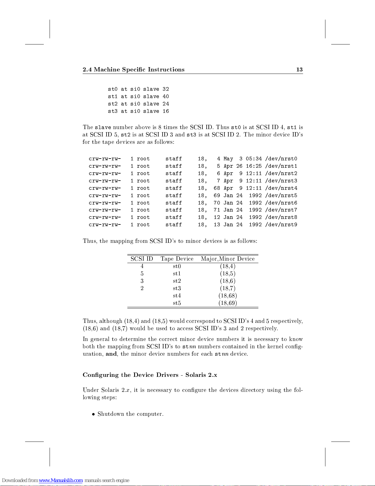
2.4 Machine Specic Instructions 13
st0 at si0 slave 32
st1 at si0 slave 40
st2 at si0 slave 24
st3 at si0 slave 16
The
slave
at SCSI ID 5,
for the tap e devices are as follows:
crw-rw-rw- 1 root staff 18, 4 May 3 05:34 /dev/nrst0
crw-rw-rw- 1 root staff 18, 5 Apr 26 16:25 /dev/nrst1
crw-rw-rw- 1 root staff 18, 6 Apr 9 12:11 /dev/nrst2
crw-rw-rw- 1 root staff 18, 7 Apr 9 12:11 /dev/nrst3
crw-rw-rw- 1 root staff 18, 68 Apr 9 12:11 /dev/nrst4
crw-rw-rw- 1 root staff 18, 69 Jan 24 1992 /dev/nrst5
crw-rw-rw- 1 root staff 18, 70 Jan 24 1992 /dev/nrst6
crw-rw-rw- 1 root staff 18, 71 Jan 24 1992 /dev/nrst7
crw-rw-rw- 1 root staff 18, 12 Jan 24 1992 /dev/nrst8
crw-rw-rw- 1 root staff 18, 13 Jan 24 1992 /dev/nrst9
Thus, the mapping from SCSI ID's to minor devices is as follows:
number above is 8 times the SCSI ID. Thus
st2
is at SCSI ID 3 and
st3
is at SCSI ID 2. The minor device ID's
st0
is at SCSI ID 4,
st1
is
SCSI ID Tape Device Ma jor,Minor Device
4 st0 (18,4)
5 st1 (18,5)
3 st2 (18,6)
2 st3 (18,7)
st4 (18,68)
st5 (18,69)
Thus, although (18,4) and (18,5) would correspond to SCSI ID's 4 and 5 respectively,
(18,6) and (18,7) would b e used to access SCSI ID's 3 and 2 respectively.
In general to determine the correct minor device numbers it is necessary to know
both the mapping from SCSI ID's tostnn
uration,
Conguring the Device Drivers - Solaris 2.x
Under Solaris 2.x, it is necessary to congure the devices directory using the fol-
lowing steps:
and
, the minor device numbers for eachstnn
Shutdown the computer.
numbers contained in the kernel cong-
device.
Page 18

14 Installation
Connect and power-up the
switch.
Boot the workstation using the
machine for all connected devices.
After the computer has bo oted the system will have created a new device le
for the
to the machine this will be named
exist, the tape unit number in the above path may be a higher number. These
les are actually symbolic links to lenames which identify the SCSI ID of the
device. For example, if the
only tap e device on the system, then
to
this path shows that the device is at SCSI ID 5.
Create a symbolic link from the ab ove le to
The
DAT-Link
/sbus@f,e0001000/esp@1,200000/st@5,0:
ln -s /dev/rmt/0 /dev/datlink0
DAT-Link
. If there are no tape devices or other
should now be ready to use.
DAT-Link
boot -r
DAT-Link
with the chosen SCSI ID set on its
command. This will recongure the
DAT-Links
/dev/rmt/0
is connected with SCSI ID 5 and is the
/dev/rmt/0
. If other tape devices also
will be a symbolic link
. The \@5" at the end of
/dev/datlink0
connected
. For example,
2.4.2 Digital Equipment Corp oration, DECstation
Manufacturer:
Models:
Operating System:
Cables Required
To connect a DECstation with the
Centronics typeconnector
It should be available from your DEC hardware supplier or can be ordered from
your
Choosing a SCSI ID
Before connecting the
use on your system. To do this, you need to rst shutdown the computer by logging
in as ro ot and running:
2
Ultrix 2.0 is
DECstation 2100, 3100
DAT-Link
Digital Equipment Corp.
Ultrix V4.2, V4.32,
on both ends. This may also be called a
supplier.
not
DAT-Link
supported
,you need to check which SCSI ID's are already in
DAT-Link
you will require a cable with a
SCSI-1
50 pin
cable.
Page 19

2.4 Machine Specic Instructions 15
shutdown -h now
Once you receivea\>" prompt, make sure all the SCSI devices connected to the
machine are turned on, and type:
test -c
This will run a self-test of the DECstation and, in the process, display a listing of
each SCSI device connected to the machine. For example, if you have a TK50 tape
drive, you should see an entry similar to:
U[5] Dev type 1 TZ
RMB 0xd0 rmv mda TZK50
Vrs 1
Format 0
Add len 0
The important thing to note is the \U[5]". This indicates the device is connected
as SCSI ID 5. Examine the display and note which devices are in use. Any ID's
between 0 and 6 which do not show a connected device can be used for the
Link
. Note that although the
9 are reserved for factory testing. ID 7 is reserved by the host computer. For
the following instructions, we will assume that the device ID chosen was 4. If you
choose a dierent ID, make sure you replace \4" with the chosen ID before typing
any commands that follow.
DAT-Link
's ID switch go es up to 9, settings 8 and
DAT-
Connecting the
The next step is to connect the
unterminate the SCSI bus temp orarily, it is recommended that you shut-down and
turn o the computer before making the connection.
The
Options
down. Then connect the
DAT-Link
terminator between the cable and the
so can cause problems with reb ooting the DECstation. Once it is ho oked up and
powered on you can rebo ot the computer. If you have trouble reb ooting, verify that
the SCSI ID selected on the
As the computer starts
is the last device on the SCSI bus, be sure to connect the provided SCSI
tz4 at sii0 slave 4 (TZxx) [TCT DAT-Link 1420]
DAT-Link
DAT-Link
switches on the rear of the
DAT-Link
DAT-Link
UNIX
,you should see a line similar to:
to the computer using the SCSI cable. If the
to the computer. Since it is necessary to
DAT-Link
DAT-Link
was not one that was already in use.
should be set with all switches
's SCSI connector. Failure to do
Page 20
16 Installation
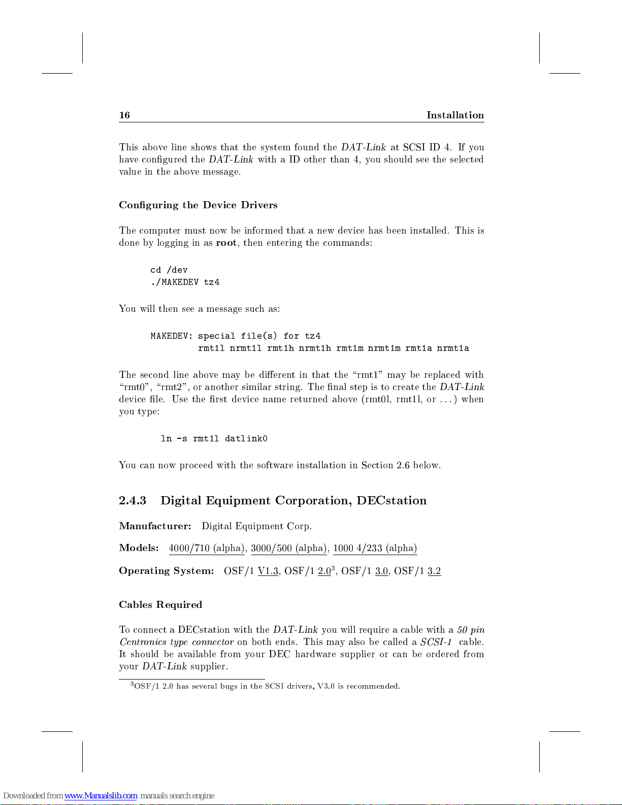
This above line shows that the system found the
have congured the
value in the ab ove message.
Conguring the Device Drivers
The computer must now be informed that a new device has b een installed. This is
done by logging in as
cd /dev
./MAKEDEV tz4
You will then see a message such as:
MAKEDEV: special file(s) for tz4
The second line abovemaybedierent in that the \rmt1" may be replaced with
\rmt0", \rmt2", or another similar string. The nal step is to create the
device le. Use the rst device name returned ab ove (rmt0l, rmt1l, or
you type:
ln -s rmt1l datlink0
DAT-Link
root
rmt1l nrmt1l rmt1h nrmt1h rmt1m nrmt1m rmt1a nrmt1a
with a ID other than 4, you should see the selected
, then entering the commands:
DAT-Link
at SCSI ID 4. If you
DAT-Link
:::
) when
You can now proceed with the software installation in Section 2.6 below.
2.4.3 Digital Equipment Corp oration, DECstation
Manufacturer:
Models:
Operating System:
Cables Required
To connect a DECstation with the
Centronics typeconnector
It should be available from your DEC hardware supplier or can be ordered from
your
3
OSF/1 2.0 has several bugs in the SCSI drivers, V3.0 is recommended.
4000/710 (alpha), 3000/500 (alpha), 1000 4/233 (alpha)
DAT-Link
Digital Equipment Corp.
OSF/1 V1.3, OSF/1 2.03, OSF/1 3.0, OSF/1 3.2
DAT-Link
on both ends. This may also be called a
supplier.
you will require a cable with a
SCSI-1
50 pin
cable.
Page 21
2.4 Machine Specic Instructions 17
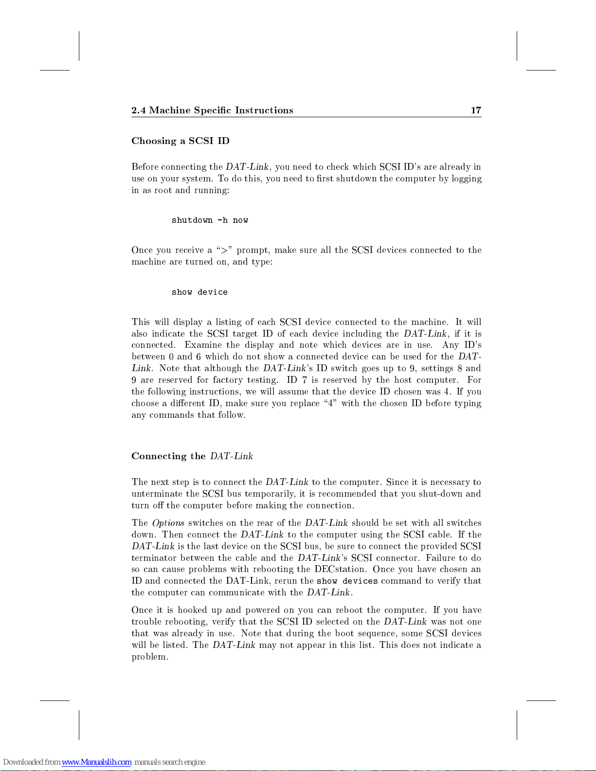
Choosing a SCSI ID
Before connecting the
use on your system. To do this, you need to rst shutdown the computer by logging
in as ro ot and running:
shutdown -h now
Once you receivea\>" prompt, make sure all the SCSI devices connected to the
machine are turned on, and type:
show device
This will display a listing of each SCSI device connected to the machine. It will
also indicate the SCSI target ID of each device including the
connected. Examine the display and note which devices are in use. Any ID's
between 0 and 6 which do not show a connected device can be used for the
Link
. Note that although the
9 are reserved for factory testing. ID 7 is reserved by the host computer. For
the following instructions, we will assume that the device ID chosen was 4. If you
choose a dierent ID, make sure you replace \4" with the chosen ID before typing
any commands that follow.
DAT-Link
,you need to check which SCSI ID's are already in
DAT-Link
DAT-Link
's ID switch go es up to 9, settings 8 and
, if it is
DAT-
Connecting the
The next step is to connect the
unterminate the SCSI bus temp orarily, it is recommended that you shut-down and
turn o the computer before making the connection.
The
Options
down. Then connect the
DAT-Link
terminator between the cable and the
so can cause problems with rebooting the DECstation. Once you havechosen an
ID and connected the DAT-Link, rerun the
the computer can communicate with the
Once it is hooked up and powered on you can rebo ot the computer. If you have
trouble rebooting, verify that the SCSI ID selected on the
that was already in use. Note that during the b oot sequence, some SCSI devices
will b e listed. The
problem.
is the last device on the SCSI bus, be sure to connect the provided SCSI
DAT-Link
DAT-Link
switches on the rear of the
DAT-Link
DAT-Link
to the computer using the SCSI cable. If the
may not appear in this list. This does not indicate a
to the computer. Since it is necessary to
DAT-Link
DAT-Link
show devices
DAT-Link
should be set with all switches
's SCSI connector. Failure to do
command to verify that
.
DAT-Link
was not one
Page 22
18 Installation
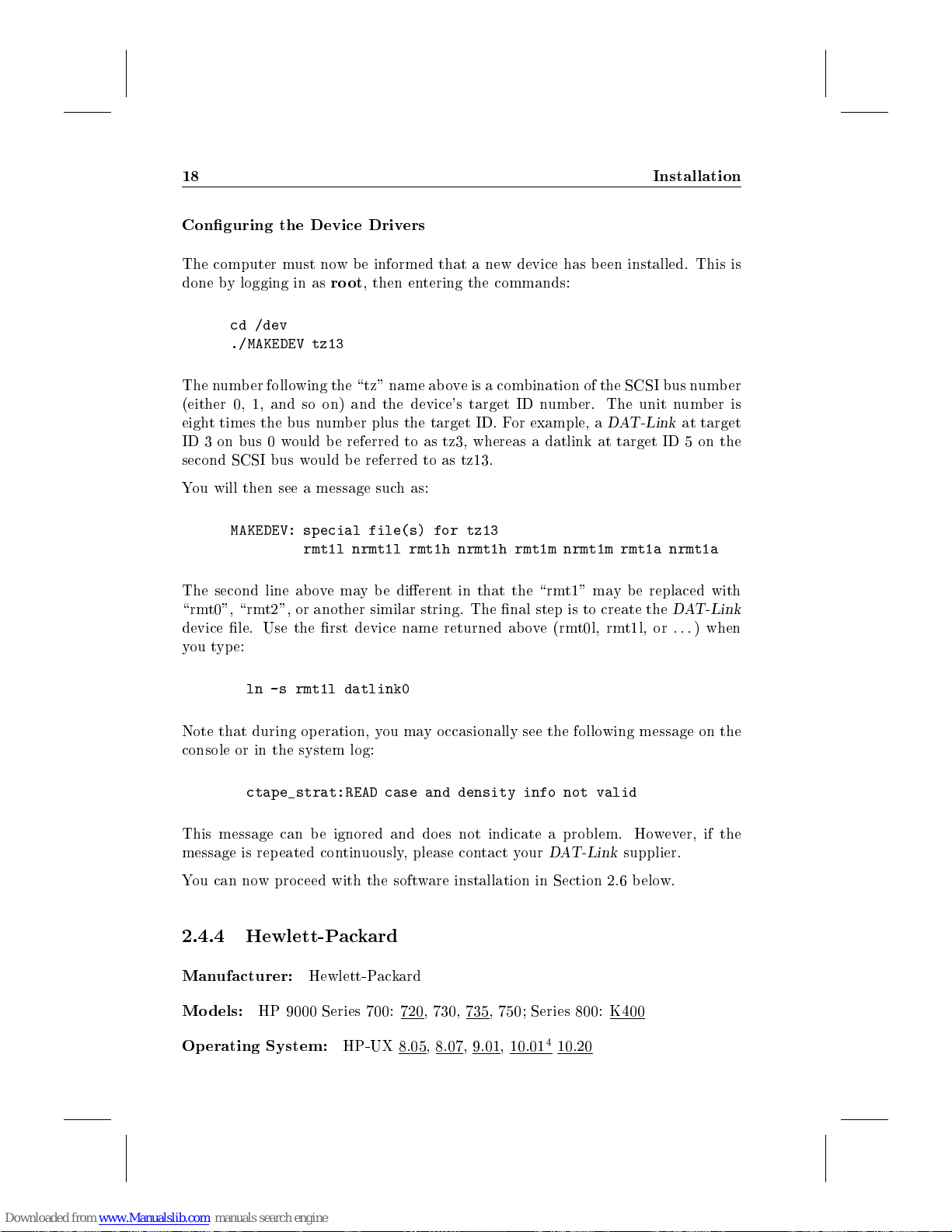
Conguring the Device Drivers
The computer must now be informed that a new device has b een installed. This is
done by logging in as
cd /dev
./MAKEDEV tz13
The number following the \tz" name ab ove is a combination of the SCSI bus number
(either 0, 1, and so on) and the device's target ID number. The unit number is
eight times the bus number plus the target ID. For example, a
ID 3 on bus 0 would be referred to as tz3, whereas a datlink at target ID 5 on the
second SCSI bus would be referred to as tz13.
You will then see a message such as:
MAKEDEV: special file(s) for tz13
The second line abovemaybedierent in that the \rmt1" may be replaced with
\rmt0", \rmt2", or another similar string. The nal step is to create the
device le. Use the rst device name returned ab ove (rmt0l, rmt1l, or
you type:
root
, then entering the commands:
DAT-Link
rmt1l nrmt1l rmt1h nrmt1h rmt1m nrmt1m rmt1a nrmt1a
at target
DAT-Link
:::
) when
ln -s rmt1l datlink0
Note that during operation, you may occasionally see the following message on the
console or in the system log:
ctape_strat:READ case and density info not valid
This message can be ignored and does not indicate a problem. However, if the
message is repeated continuously, please contact your
You can now proceed with the software installation in Section 2.6 below.
2.4.4 Hewlett-Packard
Manufacturer:
Models:
Operating System:
HP 9000 Series 700: 720, 730, 735, 750; Series 800: K400
Hewlett-Packard
HP-UX 8.05, 8.07, 9.01, 10.01410.20
DAT-Link
supplier.
Page 23
2.4 Machine Specic Instructions 19
Cables Required
To connect the HP computer with the
high-density 50 pin D connector
on the other end. This may also be called a
available from your HP hardware supplier or can be ordered from your
supplier. Make sure to connect to the HP's external, single-ended SCSI bus. The
DAT-Link
Choosing a SCSI ID
Before connecting the
in use on your system. SCSI ID's range from 0 to 7. The HP computer uses ID
7. Disk drives, tape drives and other peripherals connected to your computer will
use additional SCSI ID's. You will need to check which ID's are in use, and nd an
unused one to assign to the
ID
switch on the rear of the
9, settings 8 and 9 should not be used as these do not correspond to a valid SCSI
ID.
Connecting the
The next step is to connect the
unterminate the SCSI bus temp orarily, it is recommended that you shut-down and
turn o the computer before making the connection.
will not work with a dierential or fast/wide SCSI bus.
DAT-Link
DAT-Link
on one end and a
, you need to check which SCSI ID's are already
DAT-Link
DAT-Link
DAT-Link
DAT-Link
SCSI-1 to SCSI-2
. Once an ID has b een chosen, set the
. Note that although the switchgoesupto
to the computer. Since it is necessary to
you will require a cable with a
50 pin Centronics typeconnector
cable. It should be
DAT-Link
SCSI
The
Options
and 4 down and switch 2 up. Next, follow the instructions in Section 2.3 to connect
the
DAT-Link
trouble rebooting, verify that the SCSI ID selected on the
that was in use.
Conguring the Device Drivers
First, you should verify that system can properly see the DAT-Link. The
can b e used for this and should contain some output similar to:
10/16 bc Bus Converter
10/16/16 ext_bus HP 28655A - SCSI Interface
10/16/16.5 target
10/16/16.5.0 tape HP HP35450A -A
Note that above is the output for a
ended SCSI adapter card at slot 10/16/16 in a K400 machine. Dierent machine
switches on the rear of the
. Once it is hooked up you can reboot the computer. If you have
DAT-Link
DAT-Link
should be set with switches 1, 3,
DAT-Link
at SCSI ID 5 connected to single-
was not one
ioscan
Page 24
20 Installation
type, choice of slots or ID's, or conguration will result in slightly dierent listing.
The important thing is the presence of a tap e device reported as an HP35450A.
This is really a
DAT-Link
emulating an HP tape device.
The next step is to create a device le in the
management utility can be used for this. Once
Devices
installed tape devices including one for the
to:
Note again, that the details will change dep ending on the particular machine con-
guration. For example, the rst digit of the string '5.0.0' will always be the SCSI
ID selected for the
The next step is to select the line for the
over it and pressing return. You then need to use the
the
Files
the names of these device les bycho osing
menu. Note the short device name for the following step. Depending on the number
of tape drives already installed this will probably be
Finally, exit from
where the
proceed with the software installation in Section 2.6 b elow.
option, then the
10/12/5.0.0 stape C1533A 4 GB DDS Data Compression Tape
DAT-Link
Create Device Files
choice. This will create a set of device les in
sam
ln -s rmt/1m datlink0
1m
should b e replaced with the device name found above. You can now
Tape Drives
.
item. From there, select the
and give the following command:
/dev/rmt
sam
option. You should then have a list of
DAT-Link
DAT-Link
Show Device Files
directory. The
is started select the
which will have a line similar
by positioning the cursor
Actions
Create Default Devices
/dev/rmt
0mor1m
.
sam
Peripheral
menu to select
. You can see
from the
Actions
system
2.4.5 IBM Risc Systems/6000
Manufacturer:
Models:
Operating System:
Cables Required
To connect the RISC/6000 with the
Centronics typeconnector
It should be available from your IBM hardware supplier or can be ordered from
your
RISC/6000 Mo dels 320, 320H, 520, 530, 530H, 550, 930, 950
DAT-Link
IBM
supplier.
AIX 3.1.5
DAT-Link
on both ends. This may also be called a
you will require a cable with
SCSI-1
50 pin
cable.
Page 25
2.4 Machine Specic Instructions 21
Choosing a SCSI ID
Before connecting the
use on your system. To do this, you need to login as
manager's to ol:
smit devices
You should then see a menu on the screen listing a number of options. Use the
#
key to movedown the list until
then press return. The system will then compile a list of devices. You can scroll
through this list using the"and#keys. Lo ok for entries that have a third column
that contains four numbers of the form:
of SCSI devices you may see:
scsi0 Available 00-08 SCSI I/O Controller
cd0 Available 00-08-00-50 CD-ROM Drive
rmt1 Available 00-08-00-60 2.3 GB 8mm Tape Drive
hdisk0 Available 00-08-00-00 857 MB SCSI Disk Drive
rmt0 Available 00-08-00-40 150 MB 1/4-Inch Tape Drive
If you havemultiple SCSI I/O controllers on your machine you may see additional
entries for scsi1, scsi2, etc. In this case the \08" ab ovemay b e replaced by another
number.
The second last digit of the device number gives the SCSI ID of the device. For
example, in the list ab ove, SCSI ID's 0,4,5, and 6 are in use. Also, the IBM always
uses SCSI ID 7 for the controller. Thus ID's 1,2, and 3 would be free to be used by
DAT-Links
and 9 are reserved for factory testing.
. Note that although the
DAT-Link
,you need to check which SCSI ID's are already in
root
and run the IBM system
List All Dened Devices
00-08-00-##
DAT-Link
's ID switch go es up to 9, settings 8
. Here are some examples
is highlighted, and
Once you have determined which SCSI ID's are free, you can exit
the
F10
key.
Connecting the
The next step is to connect the
unterminate the SCSI bus temp orarily, it is recommended that you shut-down and
turn o the computer before making the connection.
The
Options
and 2 up, and switches 3 and 4 down. This places the
emulation mode necessary to communicate with the RISC/6000's software drivers.
Then connect the
is the last device on the SCSI bus, be sure to connect the provided SCSI terminator
switches on the rear of the
DAT-Link
DAT-Link
smit
DAT-Link
to the computer using the SCSI cable. If the
to the computer. Since it is necessary to
DAT-Link
should be set with switches 1
DAT-Link
into a special
by pressing
DAT-Link
Page 26
22 Installation
between the cable and the
powered on you can rebo ot the computer. If you have trouble reb ooting, verify that
the SCSI ID selected on the
Conguring the Device Drivers
The computer must now be informed that a new device has b een installed. This is
done by using
smit tape
and select, using the#key, the menu item:
and press return. A new menu will then app ear. Make sure the item
is highlighted and press return again. The next menu allows you to select which
SCSI controller the
choice. Select
smit
again after logging in as
Add a Tape Drive
8mm scsi 2.3 GB 8mm Tape Drive
scsi0 Available 00-08 SCSI I/O Controller
DAT-Link
DAT-Link
DAT-Link
's SCSI connector. Once it is hooked up and
was not one that was already in use.
root
. Enter the command:
is connected to. Usually, there will be only one
or the controller you are using if you havemultiple ones, and press return.
You should nowhave a new menu on the screen, titled
line
CONNECTION address
between two square brackets. At this p oint, type the single digit SCSI ID followed
by a zero. Do not press return or enter. For example, for a SCSI ID of 3, enter
30
. The next two lines also must b e changed, use the#key to movedown a line
to set the blo ck size. The default is 1024, but you must change it to 0. Use the
key to move to the end of the number and then press the backspace key until the
default value is erased. Then enter0. Do not press return or enter. Movedown
another line using the#key and change the
once. The screen should now app ear like this (though the CONNECTION address
may be dierent):
Tape Drive type 8mm
Tape Drive interface scsi
Description 2.3 GB 8mm Tape Drive
CONNECTION address [30] +
BLOCK size (0=variable length) [0] +#
Use DEVICE BUFFERS during writes no +
Use EXTENDED file marks no +
should be highlighted with the cursor p ositioned
yestono
Add a Tape Drive
by pressing the TAB key
. The
!
Page 27
2.4 Machine Specic Instructions 23
Once you haveveried that the information is correct, press the return key to enter
the conguration. If the conguration was successful, you should see a message
similar to the following:
COMMAND STATUS
Command: OK stdout: yes stderr: no
Before command completion, additional instructions may
appear below.
rmt1 available
The line
Your computer may indicate a dierent unit number for the device, suchas
or
or
You can now press the
from outside
to create the
device name that was displayed when the device was congured by
You can now proceed with the software installation in Section 2.6 below.
2.4.6 Solbourne
Manufacturer:
Models:
Operating System:
rmt1 available
rmt2
. Make a note of which device name and number is displayed (
rmt2
). You will need it later.
smit
. Type the command:
ln -s /dev/rmt1 /dev/datlink0
datlink0
S400DX
indicates that the
F10
key to exit from
system device. Note that
Solbourne
OS/MP 4.1A.3
DAT-Link
smit
has b een congured as
. One last thing needs to be done
rmt1
rmt0,rmt1
should be replaced by the
smit
.
rmt1
rmt0
.
,
Cables Required
To connect the workstation with the
high-density 50 pin D connector
on the other end. This may also b e called a
be available from your Solb ourne hardware supplier or can be ordered from your
DAT-Link
supplier.
DAT-Link
on one end and a
SCSI-1 to SCSI-2
you will require a cable with a
50 pin Centronics typeconnector
cable. It should
Page 28

24 Installation
Choosing a SCSI ID
If you are using the standard software as supplied by Solb ourne, then SCSI ID's 4
and 5 are reserved for tap e drives, or devices suchasthe
have a tap e drive connected to your machine, check its SCSI ID setting which should
be either 4 or 5. You can then use the other number for the
ID's are already b eing used, or if you wish to install multiple
then a custom
administrator. Arbitrary SCSI ID's can then be chosen in the range 0 to 6.
UNIX
kernel must be built for the machine | a job for a system
DAT-Link
DAT-Link
DAT-Link
. If you already
. If both
devices,
5
Connecting the
The next step is to connect the
unterminate the SCSI bus temp orarily, it is recommended that you shut-down and
turn o the computer before making the connection.
Make sure the
up and all the other switches down. Then connect the
using the SCSI cable. If the
to connect the provided SCSI terminator between the cable and the
SCSI connector.
Once it is hooked up and powered on you can rebo ot the computer. If you have
trouble rebooting, verify that the SCSI ID selected on the
that was in use. Finally,power on the
Conguring the Device Drivers
Next, you need to create a device in the
be a character device with the major and minor device numbers corresponding to
a standard 1/4 inch tap e drive at the SCSI address selected on the
for example, the
commands:
DAT-Link
Options
DAT-Link
DAT-Link
switches on the rear of the
DAT-Link
is set for SCSI ID 5, the device can be created with the
to the computer. Since it is necessary to
DAT-Link
is the last device on the SCSI bus, b e sure
DAT-Link
/dev
.
directory called
are set with switch1
DAT-Link
DAT-Link
to the computer
datlink0
DAT-Link
DAT-Link
was not one
. It should
. If,
's
/etc/mknod /dev/datlink0 c 18 5
chmod 666 /dev/datlink0
For SCSI ID 4, the equivalent commands are:
/etc/mknod /dev/datlink0 c 18 4
chmod 666 /dev/datlink0
5
The
testing. The Solb ourne itself uses SCSI ID 7
DAT-Link
's SCSI ID switch goes up to 9, but the 8 and 9 settings are only for factory
Page 29
2.4 Machine Specic Instructions 25
Note that you will need to be logged in as
You can now proceed with the software installation in Section 2.6 below.
2.4.7 Sony NEWS Workstations
Manufacturer:
Models:
Operating System:
Cables Required
To connect the Sony with the
tronics type connectors
should b e available from your Sony hardware supplier or can be ordered from your
DAT-Link
Choosing a SCSI ID
If you are using the standard software as supplied by Sony, then SCSI ID's 4, 5, and
6 are reserved for tape drives, or devices suchasthe
a tap e drive connected to your machine, check its SCSI ID setting which should
be either 4, 5, or 6. You can then use the other number for the
ID's are already b eing used, or if you wish to install multiple
then a custom
administrator. Arbitrary SCSI ID's can then be chosen in the range 0 to 6.
NWS-1720, NWS-5000
supplier.
Sony
NEWS 4.2c
DAT-Link
on both ends. This may also be called a
UNIX
kernel must be built for the machine | a job for a system
root
to execute the above commands.
you will require a cable with
SCSI-1
DAT-Link
. If you already have
DAT-Link
DAT-Link
50 pin Cen-
cable. It
. If all
devices,
6
Connecting the
The next step is to connect the
unterminate the SCSI bus temp orarily, it is recommended that you shut-down and
turn o the computer before making the connection.
Make sure the
down. Then connect the
DAT-Link
terminator b etween the cable and the
6
The
testing. The Sony itself uses SCSI ID 7
Options
is the last device on the SCSI bus, be sure to connect the provided SCSI
DAT-Link
DAT-Link
DAT-Link
switches on the rear of the
DAT-Link
's SCSI ID switch goes up to 9, but the 8 and 9 settings are only for factory
to the computer. Since it is necessary to
DAT-Link
to the computer using the SCSI cable. If the
DAT-Link
's SCSI connector.
are set with all switches
Page 30
26 Installation
Once it is hooked up and powered on you can rebo ot the computer. If you have
trouble rebooting, verify that the SCSI ID selected on the
that was in use.
Conguring the Device Drivers
DAT-Link
was not one
Next, you need to create a device in the
be a character device with the major and minor device numbers corresponding to
a standard 1/4 inch tap e drive at the SCSI address selected on the
for example, the
commands:
/etc/mknod /dev/datlink0 c 16 4
chmod 666 /dev/datlink0
For SCSI ID 6, the equivalent commands are:
/etc/mknod /dev/datlink0 c 16 5
chmod 666 /dev/datlink0
Note that you will need to be logged in as
You can now proceed with the software installation in Section 2.6 below.
2.4.8 Silicon Graphics
Manufacturer:
Models:
DAT-Link
Silicon Graphics
Indigo,Indy,O2
is set for SCSI ID 5, the device can be created with the
/dev
directory called
root
datlink0
to execute the above commands.
. It should
DAT-Link
. If,
Operating System:
NOTE
have rmware that is incompatible with the SGI op erating system. If you havea
DAT-Link
machine, contact your
Cables Required
To connect an Indigo to the
Centronics typeconnector
should be available from your Silicon Graphics hardware supplier or can be ordered
from your
: Some versions of the
with a serial number of T0450 or lower, and wish to connect it to an SGI
DAT-Link
IRIX 4.0.1, 4.0.5F, 5.1, 5.2, 6.2, 6.3
DAT-Link
DAT-Link
on both ends. This may also be called a
supplier (CB-CENT).
supplier for an upgrade.
DAT-Link
, with serial numbers up to T0450, may
you will require a cable with a
SCSI-1
50 pin
cable. It
Page 31
2.4 Machine Specic Instructions 27
For the Indy computers you will required a cable with a
connector
This may also be called a
your SGI hardware supplier or can be ordered from your
MICROD).
For the O2 workstations, you will need a cable with a
one end and a
called a
supplier. Note: If you want to mix both wide (68-pin) and narrow (50-pin) SCSI
devices to the O2's bus, you have connect the 68-pin devices rst on the bus, and
then daisychain the 50-pin devices, like the
Choosing a SCSI ID
You must select a SCSI ID for the
drive, tap e drive, CD ROM or other device on the same SCSI bus. Be aware that
some models have 2 SCSI controllers. For example, the O2's external SCSI bus is
bus 1, bus 0 being the internal one.
SCSI ID's can be chosen in the range 1 to 6. Once an ID is chosen, set the SCSI
ID switch on the rear of the
read when the
the
on one end and a
50 pin Centronics typeconnector
SCSI-3 to SCSI-1
DAT-Link
DAT-Link
.
50 pin Centronics type connector
SCSI-1 to SCSI-2
cable. It should be available from your SGI hardware
DAT-Link
DAT-Link
is p owered up, so if you change it, b e sure to p ower-cycle
accordingly.7Note that this switch is only
cable. It should be available from
on the other end. This may also be
DAT-Link
that is not already in use by a disk
high-density 50 pin D
on the other end.
DAT-Link
wide 68-pin D connector
.
supplier (CB-
on
The SCSI ID's of all devices connected, including the
by using the
Monitor when the system is shut down. See the users manuals supplied with your
workstation for details on using
Connecting the
The next step is to connect the
unterminate the SCSI bus temp orarily, it is recommended that you shut-down and
turn o the computer before making the connection.
The
Options
down. Then connect the
DAT-Link
terminator b etween the cable and the
Once it is hooked up and powered on you can rebo ot the computer. If you have
trouble rebooting, verify that the SCSI ID selected on the
7
The
testing. The computer itself uses SCSI ID 0. Although SCSI ID 7 should work, IRIX do es not
appear to recognize it.
hinv
command either while the system is running or from the System
hinv
.
DAT-Link
DAT-Link
switches on the rear of the
DAT-Link
is the last device on the SCSI bus, be sure to connect the provided SCSI
DAT-Link
's SCSI ID switch goes up to 9, but the 8 and 9 settings are only for factory
to the computer. Since it is necessary to
DAT-Link
to the computer using the SCSI cable. If the
DAT-Link
DAT-Link
should be set with all switches
's SCSI connector.
, can be checked
DAT-Link
was not one
Page 32
28 Installation
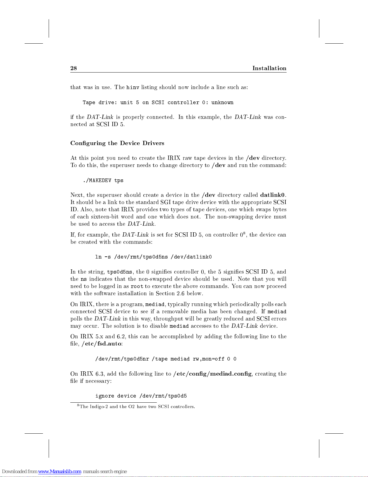
that was in use. The
Tape drive: unit 5 on SCSI controller 0: unknown
if the
DAT-Link
nected at SCSI ID 5.
Conguring the Device Drivers
At this p ointyou need to create the IRIX raw tape devices in the
To do this, the sup eruser needs to change directory to
./MAKEDEV tps
Next, the superuser should create a device in the
It should be a link to the standard SGI tap e drive device with the appropriate SCSI
ID. Also, note that IRIX provides twotypes of tape devices, one whichswaps bytes
of each sixteen-bit word and one which does not. The non-swapping device must
be used to access the
If, for example, the
be created with the commands:
ln -s /dev/rmt/tps0d5ns /dev/datlink0
hinv
listing should now include a line such as:
is prop erly connected. In this example, the
/dev
/dev
directory called
DAT-Link
DAT-Link
.
is set for SCSI ID 5, on controller 08, the device can
DAT-Link
/dev
and run the command:
was con-
directory.
datlink0
.
In the string,
thensindicates that the non-swapped device should be used. Note that you will
need to be logged in as
with the software installation in Section 2.6 b elow.
On IRIX, there is a program,
connected SCSI device to see if a removable media has been changed. If
polls the
may occur. The solution is to disable
On IRIX 5.x and 6.2, this can be accomplished by adding the following line to the
le,
/etc/fsd.auto
On IRIX 6.3, add the following line to
le if necessary:
8
The Indigo-2 and the O2 havetwo SCSI controllers.
tps0d5ns
DAT-Link
/dev/rmt/tps0d5nr /tape mediad rw,mon=off 0 0
ignore device /dev/rmt/tps0d5
, the 0 signies controller 0, the 5 signies SCSI ID 5, and
root
to execute the above commands. You can now pro ceed
mediad
in this way, throughput will be greatly reduced and SCSI errors
:
,typically running which periodically polls each
mediad
accesses to the
/etc/cong/mediad.cong
DAT-Link
, creating the
mediad
device.
Page 33
2.4 Machine Specic Instructions 29
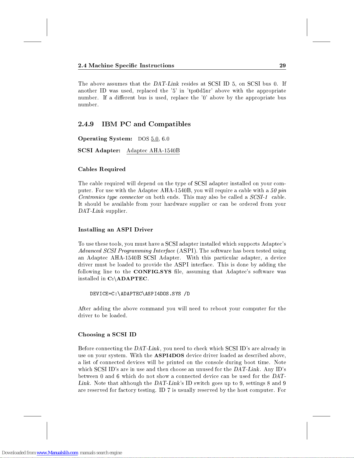
The above assumes that the
another ID was used, replaced the '5' in 'tps0d5nr' above with the appropriate
number. If a dierent bus is used, replace the '0' above by the appropriate bus
number.
2.4.9 IBM PC and Compatibles
Operating System:
SCSI Adapter:
Cables Required
The cable required will depend on the type of SCSI adapter installed on your com-
puter. For use with the Adaptec AHA-1540B, you will require a cable with a
Centronics typeconnector
It should be available from your hardware supplier or can be ordered from your
DAT-Link
Installing an ASPI Driver
To use these tools, you must have a SCSI adapter installed which supports Adaptec's
Advanced SCSI Programming Interface(ASPI
an Adaptec AHA-1540B SCSI Adapter. With this particular adapter, a device
driver must be loaded to provide the
following line to the
installed inC:n
supplier.
Adaptec AHA-1540B
CONFIG.SYS
ADAPTEC
DAT-Link
DOS
, 6.0
5.0
on both ends. This may also be called a
.
resides at SCSI ID 5, on SCSI bus 0. If
). The software has b een tested using
ASPI
interface. This is done by adding the
le, assuming that Adaptec's software was
SCSI-1
50 pin
cable.
DEVICE=C:\ADAPTEC\ASPI4DOS.SYS /D
After adding the above command you will need to reboot your computer for the
driver to be loaded.
Choosing a SCSI ID
Before connecting the
use on your system. With the
a list of connected devices will be printed on the console during b oot time. Note
which SCSI ID's are in use and then choose an unused for the
between 0 and 6 which do not show a connected device can be used for the
Link
. Note that although the
are reserved for factory testing. ID 7 is usually reserved by the host computer. For
DAT-Link
ASPI4DOS
DAT-Link
,you need to check which SCSI ID's are already in
device driver loaded as described above,
DAT-Link
's ID switch goes up to 9, settings 8 and 9
. Any ID's
DAT-
Page 34

30 Installation
the following instructions, we will assume that the device ID chosen was 4. If you
choose a dierent ID, make sure you replace \4" with the chosen ID before typing
any commands that follow.
Connecting the
The next step is to connect the
unterminate the SCSI bus temp orarily, it is recommended that you shut-down and
turn o the computer before making the connection.
The
Options
down and the
DAT-Link
device on the SCSI bus, be sure to connect the provided SCSI terminator between
the cable and the
with rebo oting the computer. Once it is hooked up and powered on you can reboot
the computer. If you have trouble rebooting, verify that the SCSI ID selected on
the
DAT-Link
As the computer starts, if you are using
to:
This above line shows that the system found the
have congured the
value in the ab ove message.
You can now proceed with the software installation in Section 2.6.4 below.
to the computer using the SCSI cable. If the
Target 4 TCT DAT-Link 1638
DAT-Link
DAT-Link
switches on the rear of the
SCSI ID
was not one that was already in use.
switchmust b e set as described ab ove. Then connect the
DAT-Link
DAT-Link
's SCSI connector. Failure to do so can cause problems
with a ID other than 4, you should see the selected
to the computer. Since it is necessary to
DAT-Link
ASPI4DOS
should be set with all switches
DAT-Link
,you should see a line similar
DAT-Link
at SCSI ID 4. If you
is the last
Dierences in DOS Implementation
The NetAudio programs described elsewhere is this manual are available under
DOS
as individual executables. The usage of these tools diers slightly from that
described elsewhere in this manual. In particular:
There is no NetAudio server (netaudiod or naserver) under
programs communicate directly with the
that the
This means that programs such as
lasting eect and are thus ineective.
The argument to the -u option for each of the NetAudio clients should be the
SCSI address of the
form should be 'host:unit'.
DAT-Link
DOS
. All client
DAT-Link
will always be in it's default state when a tool is executed.
DAT-Link
naset
, even though the online help states that the
and
. Note that this means
naloaddsp
will not have a
Page 35
2.4 Machine Specic Instructions 31
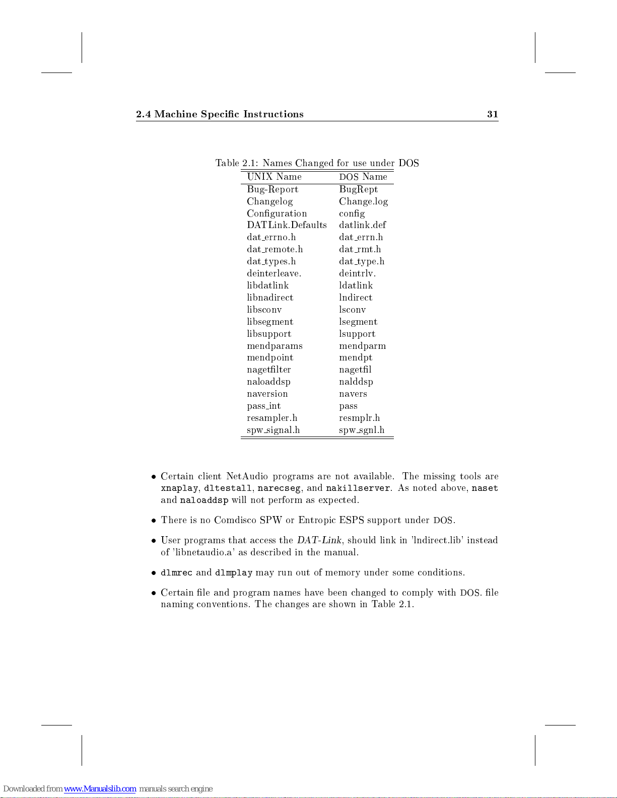
Table 2.1: Names Changed for use under DOS
UNIX Name
Bug-Report BugRept
Changelog Change.log
Conguration cong
DATLink.Defaults datlink.def
dat errno.h dat errn.h
dat remote.h dat rmt.h
dat types.h dat type.h
deinterleave. deintrlv.
libdatlink ldatlink
libnadirect lndirect
libsconv lsconv
libsegment lsegment
libsupport lsupp ort
mendparams mendparm
mendpoint mendpt
nagetlter nagetl
naloaddsp nalddsp
naversion navers
pass int pass
resampler.h resmplr.h
spw signal.h spw sgnl.h
DOS
Name
Certain client NetAudio programs are not available. The missing tools are
xnaplay,dltestall,narecseg
and
naloaddsp
There is no Comdisco SPW or Entropic ESPS support under
User programs that access the
of 'libnetaudio.a' as described in the manual.
dlmrec
Certain le and program names have been changed to comply with
naming conventions. The changes are shown in Table 2.1.
and
will not p erform as expected.
dlmplay
may run out of memory under some conditions.
, and
nakillserver
DAT-Link
. As noted above,
DOS
.
, should link in 'lndirect.lib' instead
DOS
naset
. le
Page 36
32 Installation
2.4.10 NeXT
Manufacturer:
Operating System:
Cables Required
To connect the NeXT with the
density 50 pin D connector
the other end. This may also be called a
available from your NeXT hardware supplier or can b e ordered from your
supplier.
Choosing a SCSI ID
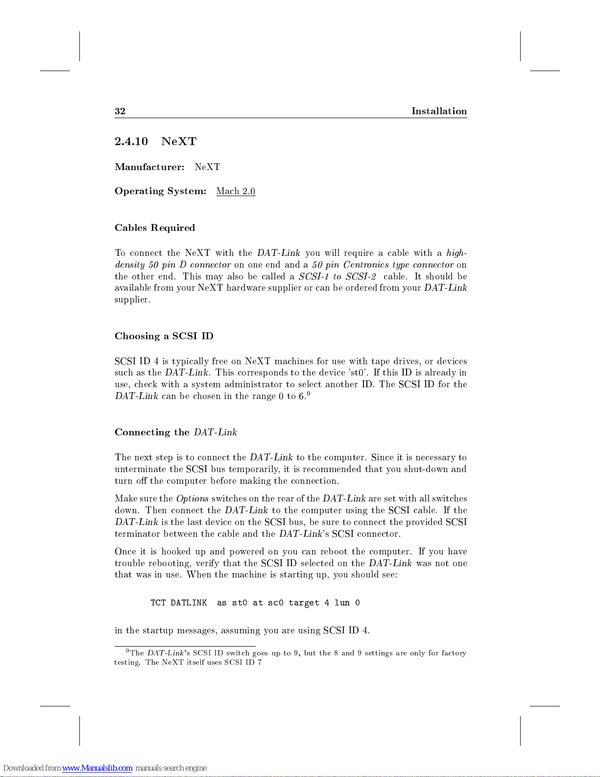
SCSI ID 4 is typically free on NeXT machines for use with tape drives, or devices
suchasthe
use, check with a system administrator to select another ID. The SCSI ID for the
DAT-Link
Connecting the
DAT-Link
can b e chosen in the range 0 to 6.
NeXT
Mach 2.0
DAT-Link
on one end and a
. This corresp onds to the device 'st0'. If this ID is already in
DAT-Link
you will require a cable with a
50 pin Centronics typeconnector
SCSI-1 to SCSI-2
9
cable. It should be
DAT-Link
high-
on
The next step is to connect the
unterminate the SCSI bus temp orarily, it is recommended that you shut-down and
turn o the computer before making the connection.
Make sure the
down. Then connect the
DAT-Link
terminator b etween the cable and the
Once it is hooked up and powered on you can rebo ot the computer. If you have
trouble rebooting, verify that the SCSI ID selected on the
that was in use. When the machine is starting up, you should see:
in the startup messages, assuming you are using SCSI ID 4.
9
The
testing. The NeXT itself uses SCSI ID 7
Options
is the last device on the SCSI bus, be sure to connect the provided SCSI
TCT DATLINK as st0 at sc0 target 4 lun 0
DAT-Link
switches on the rear of the
's SCSI ID switch goes up to 9, but the 8 and 9 settings are only for factory
DAT-Link
DAT-Link
to the computer. Since it is necessary to
DAT-Link
to the computer using the SCSI cable. If the
DAT-Link
's SCSI connector.
are set with all switches
DAT-Link
was not one
Page 37
2.4 Machine Specic Instructions 33
Conguring the Device Drivers
Next, you need to create a device in the
used SCSI ID 4 for the
device to
Note that you will need to be logged in as
You can now proceed with the software installation in Section 2.6 below.
2.4.11 Other
The
If you have a computer not listed here, please contact your
information on support and installation instructions.
datlink0
ln -s /dev/nrst0 /dev/datlink0
chmod 666 /dev/datlink0
DAT-Link
will work with most
:
UNIX
DAT-Link
-Based Computers
, you just need to link the standard tap e drive
/dev
directory called
root
to execute the above commands.
UNIX
-based computers that have a SCSI bus.
datlink0
DAT-Link
. If you
supplier for
Page 38
34 Installation
2.5 Connecting to a Digital Audio Device
Now that the
other half of the connection|between the
This will usually be a Digital Audio Tape (DAT) recorder, but you can also connect
the
DAT-Link
Cassette (DCC), a standalone digital-to-analog or analog-to-digital converter, or a
special eects processor. The only requirement is that the device has a digital input
and/or digital output.
The
DAT-Link
SPDIF:
chines. The connectors are standard phono connectors. This type of connector
may also be lab el \IEC Type II" or simply \Digital I/O". Standard analog
phono cables can usually be used for the digital data, however some cables
that are designed for analog may not be able to carry the high rates needed for
the digital data, especially over long distances. Many high-end audio stores
carry special digital phono cables that solve this problem.
AES/EBU:
It uses three-pin XLR connectors. Cables designed for analog applications
work ne for AES/EBU connections as well. However, note that shielded
cables (most cables are shielded) must be used, otherwise unacceptable levels
of radio or TV interference may be generated by the
cabling is the preferred choice for long distance runs between the
and the digital audio equipment.
DAT-Link
to a Compact Disk (CD) player, a MiniDisk (MD), a Digital Compact
supports three dierenttypes of connections to digital audio devices:
This is the interconnect that is most often used on consumer DAT ma-
This type of cabling is most often found on professional equipment.
is connected to your computer, you need to make the
DAT-Link
and a digital audio device.
DAT-Link
. This type of
DAT-Link
Fiber-optic:
to the
moving to this type of connection. Note that the type of ber-optic cables
used by digital audio equipment limits the distance of this type of connection
to ab out 3 meters (10 feet).
If the appropriate cables were not included with your digital audio equipment, they
can b e obtained at any audio store which carries digital equipment.
Using the connection type available on your equipment, connect the devices using
two cables, one for each direction | playback and record. If you're using a CD
player or other device which is not able to make recordings, you will only need one
cable | from the CD player's digital output to the
Multiple devices can b e connected to a single
connections. When audio output is generated, the data app ears on all three output
connectors. For audio input, the programs provided allow the user to select which
connector is used for the input source. You can, for example, connect a DAT
machine via the
Many CD players use a ber-optic output which can be connected
DAT-Link
using this connection. Also, DAT machines are increasingly
IEC TypeII
DAT-Link
DAT-Link
connectors and a CD player via the
's digital input.
as long as they use dierent
ber-optic
input.
Page 39
2.6 Software Installation 35
The
DAT-Link
computer.
It is imp ortant to realize that there are subtle dierences in the control information
that is sent along with the audio data on these dierent connectors. The two
main formats of this information can be broadly categorized into
Professional
which format to use. For most applications, if you are using the SPDIF or ber-
optic connections, the
the
professional
at all unless the correct format is used.
2.6 Software Installation
software will then allow you to select the input source from the
Consumer
. The various programs used with the
consumer
format should b e selected. Some DAT machines will not op erate
format should b e used. For AES/EBU connections,
DAT-Link
allow you to select
and
The
DAT-Link
DOS diskettes, a data DAT tap e (DDS), or audio DAT tape which can be read
using the
types of workstations; each with its own unique type of tap e drive, DAT tape is
the preferred distribution media. If you received the software on cartridge tape or
DDS data DAT, refer to Section 2.6.3 for instructions on loading the tape. For DOS
installations, you will need to follow the instructions in Section 2.6.4.
2.6.1 Installation from DAT Tap e
The
DAT-Link
using the
4mm data tap e drive|an audio DAT machine and the
Before b eginning the installation, you should choose a directory in which to install
the source software. You will require approximately 8 Mbytes of free space for the
installation. The following instructions assume that the sources will b e placed in
/usr/local/src/datlink
user that runs the installation must have write permission in this directory and
also in the directories that will b e ultimately used to hold the executable programs,
manual pages, etc. Since these will usually be system directories, you may need to
become super-user to install the software.
software is distributed on four types of media:
DAT-Link
DAT-Link
itself. Since the
software is normally distributed on aDATtape that can be read
. Note that the supplied tape can
, but any directory may be substituted. Note that the
DAT-Link
can be used on many dierent
not
DAT-Link
1
00
cartridge tape,
4
be read using a DATor
must b e used.
Installation Steps (
1. Change directory to the lo cation where you want the
stalled. See section 2.6.1 above for assistance in choosing an appropriate
directory.
DAT-Link
+):
DAT-Link
sources in-
Page 40
36 Installation
2. Connect the
sections.
3. If the
4. Connect the
5. Insert the distribution tap e in the DAT machine and make sure it is rewound
to the b eginning.
6. Type:
7. Press
command.
Within about 25 seconds of pressing play, theddcommand should exit with the
message:
50+0 records in
50+0 records out
If you do not see the ab ove message, or see an error message during the loading
process, stop the tape and repeat the above steps. If the error persists refer to
Section A.3 in the Appendices to troubleshoot the problem.
DAT-Link
DAT-Link
DAT-Link
dd if=/dev/datlink0 bs=64512 of=/tmp/dldist count=50
play
on the DAT machine within a few seconds of executing the
+ and congure the computer as described in previous
+was already on, turn its power o and on again.
+ to an audio DAT player.
dd
Once theddcommand has completed, you can stop the tape and begin the instal-
lation pro cedure by executing the command:
/bin/sh /tmp/dldist
You should then see the message:
DAT-Link Source Installation
----------------------------
which will be followed after a few seconds by:
Finished extracting sources.
Setting up sources...
The source les will be extracted into you current directory and you will then be
prompted for various conguration options as described in the section 2.6.2 b elow.
Page 41
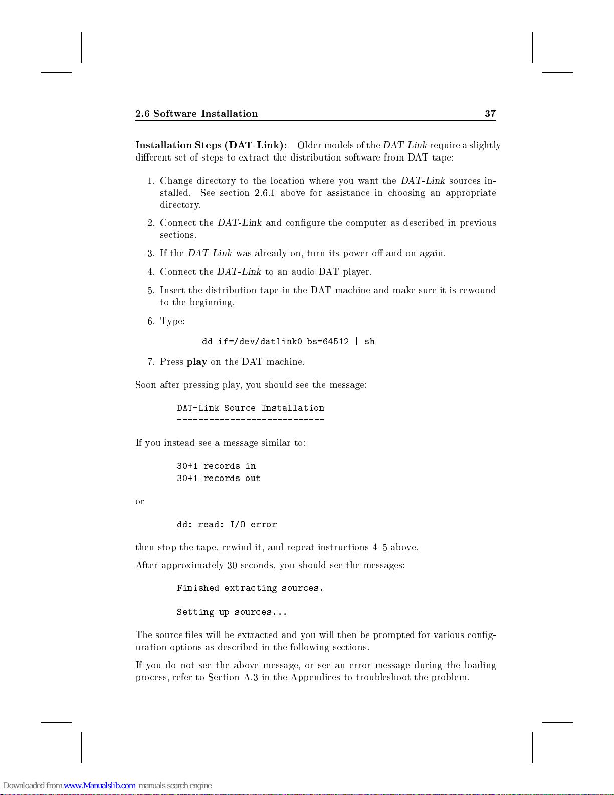
2.6 Software Installation 37
Installation Steps (DAT-Link):
dierent set of steps to extract the distribution software from DAT tape:
1. Change directory to the lo cation where you want the
stalled. See section 2.6.1 above for assistance in choosing an appropriate
directory.
2. Connect the
sections.
3. If the
4. Connect the
5. Insert the distribution tap e in the DAT machine and make sure it is rewound
to the b eginning.
6. Type:
7. Press
Soon after pressing play,you should see the message:
play
DAT-Link Source Installation
----------------------------
DAT-Link
DAT-Link
dd if=/dev/datlink0 bs=64512 | sh
was already on, turn its power o and on again.
DAT-Link
on the DAT machine.
and congure the computer as described in previous
to an audio DAT player.
Older models of the
DAT-Link
DAT-Link
require a slightly
sources in-
If you instead see a message similar to:
30+1 records in
30+1 records out
or
dd: read: I/O error
then stop the tape, rewind it, and repeat instructions 4{5 above.
After approximately 30 seconds, you should see the messages:
Finished extracting sources.
Setting up sources...
The source les will b e extracted and you will then be prompted for various cong-
uration options as described in the following sections.
If you do not see the ab ove message, or see an error message during the loading
process, refer to Section A.3 in the App endices to troublesho ot the problem.
Page 42
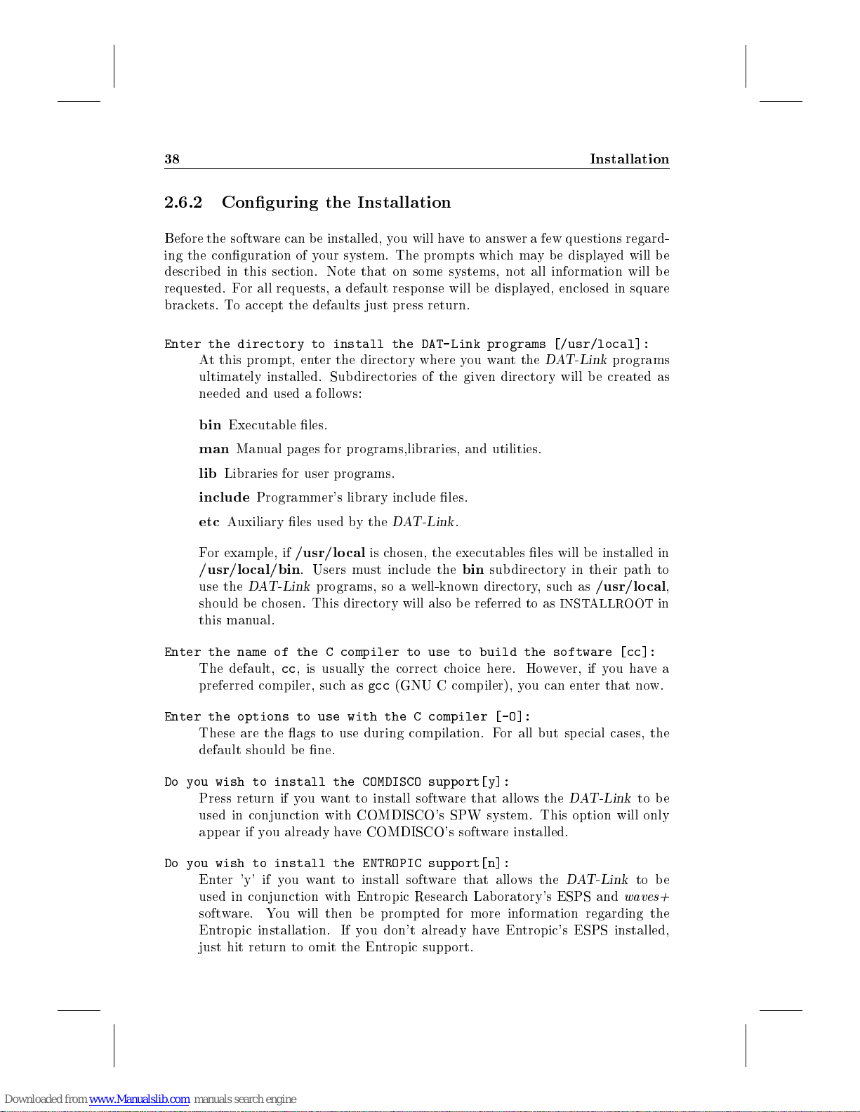
38 Installation
2.6.2 Conguring the Installation
Before the software can be installed, you will have to answer a few questions regard-
ing the conguration of your system. The prompts whichmay b e displayed will b e
described in this section. Note that on some systems, not all information will be
requested. For all requests, a default resp onse will be displayed, enclosed in square
brackets. To accept the defaults just press return.
Enter the directory to install the DAT-Link programs [/usr/local]:
At this prompt, enter the directory where you want the
ultimately installed. Subdirectories of the given directory will be created as
needed and used a follows:
bin
Executable les.
man
Manual pages for programs,libraries, and utilities.
lib
Libraries for user programs.
DAT-Link
programs
include
etc
For example, if
/usr/local/bin
use the
should be chosen. This directory will also be referred to as
this manual.
Enter the name of the C compiler to use to build the software [cc]:
The default,cc, is usually the correct choice here. However, if you have a
preferred compiler, suchas
Enter the options to use with the C compiler [-O]:
These are the ags to use during compilation. For all but sp ecial cases, the
default should b e ne.
Do you wish to install the COMDISCO support[y]:
Press return if you want to install software that allows the
used in conjunction with COMDISCO's SPW system. This option will only
appear if you already have COMDISCO's software installed.
Do you wish to install the ENTROPIC support[n]:
Enter 'y' if you want to install software that allows the
used in conjunction with Entropic Research Lab oratory's ESPS and
software. You will then be prompted for more information regarding the
Entropic installation. If you don't already have Entropic's ESPS installed,
just hit return to omit the Entropic support.
Programmer's library include les.
Auxiliary les used by the
/usr/local
. Users must include the
DAT-Link
programs, so a well-known directory, suchas
DAT-Link
is chosen, the executables les will be installed in
gcc
(GNU C compiler), you can enter that now.
.
bin
subdirectory in their path to
INSTALLROOT
DAT-Link
DAT-Link
/usr/local
to be
to be
waves+
,
in
Page 43
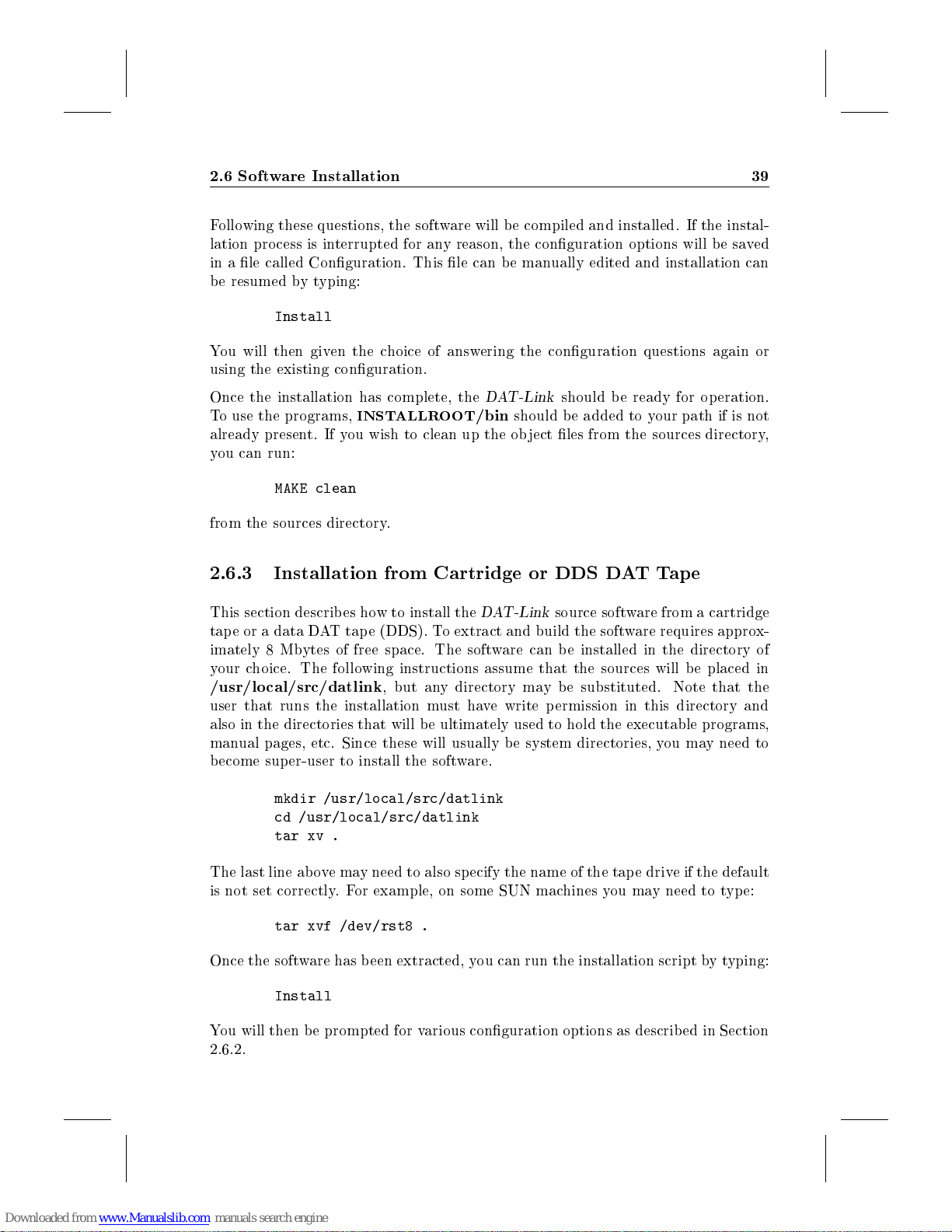
2.6 Software Installation 39
Following these questions, the software will be compiled and installed. If the instal-
lation pro cess is interrupted for any reason, the conguration options will be saved
in a le called Conguration. This le can b e manually edited and installation can
be resumed bytyping:
Install
You will then given the choice of answering the conguration questions again or
using the existing conguration.
Once the installation has complete, the
To use the programs,
already present. If you wish to clean up the ob ject les from the sources directory,
you can run:
MAKE clean
from the sources directory.
2.6.3 Installation from Cartridge or DDS DAT Tap e
This section describes how to install the
tape or a data DAT tap e (DDS). To extract and build the software requires approx-
imately 8 Mbytes of free space. The software can b e installed in the directory of
your choice. The following instructions assume that the sources will b e placed in
/usr/local/src/datlink
user that runs the installation must have write permission in this directory and
also in the directories that will b e ultimately used to hold the executable programs,
manual pages, etc. Since these will usually be system directories, you may need to
become super-user to install the software.
mkdir /usr/local/src/datlink
cd /usr/local/src/datlink
tar xv .
INSTALLROOT
, but any directory may be substituted. Note that the
DAT-Link
/bin
should be added to your path if is not
DAT-Link
should be ready for op eration.
source software from a cartridge
The last line abovemay need to also specify the name of the tape drive if the default
is not set correctly. For example, on some SUN machines you may need to type:
tar xvf /dev/rst8 .
Once the software has been extracted, you can run the installation script bytyping:
Install
You will then be prompted for various conguration options as described in Section
2.6.2.
Page 44
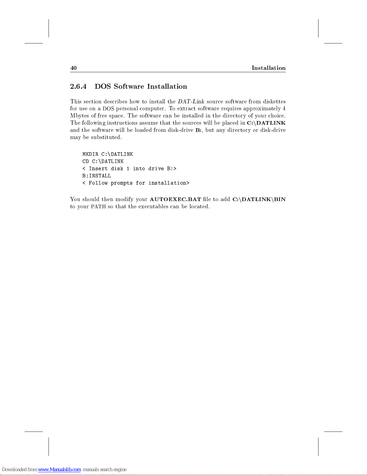
40 Installation
2.6.4 DOS Software Installation
This section describes how to install the
for use on a
Mbytes of free space. The software can b e installed in the directory of your choice.
The following instructions assume that the sources will be placed inC:n
and the software will b e loaded from disk-driveB:, but any directory or disk-drive
may be substituted.
MKDIR C:\DATLINK
CD C:\DATLINK
< Insert disk 1 into drive B:>
B:INSTALL
< Follow prompts for installation>
You should then modify your
to your
DOS
personal computer. To extract software requires approximately 4
AUTOEXEC.BAT
PATH
so that the executables can be located.
DAT-Link
source software from diskettes
DATLINK
le to addC:n
DATLINKnBIN
Page 45
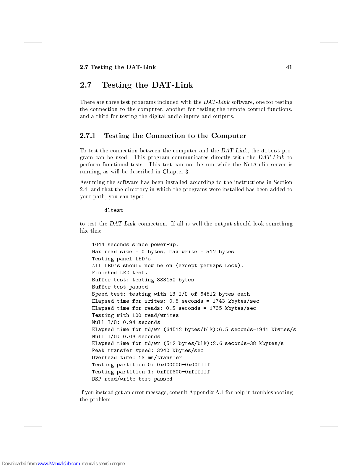
2.7 Testing the DAT-Link 41
2.7 Testing the DAT-Link
There are three test programs included with the
the connection to the computer, another for testing the remote control functions,
and a third for testing the digital audio inputs and outputs.
2.7.1 Testing the Connection to the Computer
To test the connection between the computer and the
gram can be used. This program communicates directly with the
perform functional tests. This test can not be run while the NetAudio server is
running, as will be described in Chapter 3.
Assuming the software has b een installed according to the instructions in Section
2.4, and that the directory in which the programs were installed has been added to
your path, you can type:
dltest
to test the
like this:
DAT-Link
1044 seconds since power-up.
Max read size = 0 bytes, max write = 512 bytes
Testing panel LED's
All LED's should now be on (except perhaps Lock).
Finished LED test.
Buffer test: testing 883152 bytes
Buffer test passed
Speed test: testing with 13 I/O of 64512 bytes each
Elapsed time for writes: 0.5 seconds = 1743 kbytes/sec
Elapsed time for reads: 0.5 seconds = 1735 kbytes/sec
Testing with 100 read/writes
Null I/O: 0.94 seconds
Elapsed time for rd/wr (64512 bytes/blk):6.5 seconds=1941 kbytes/s
Null I/O: 0.03 seconds
Elapsed time for rd/wr (512 bytes/blk):2.6 seconds=38 kbytes/s
Peak transfer speed: 3240 kbytes/sec
Overhead time: 13 ms/transfer
Testing partition 0: 0x000000-0x00ffff
Testing partition 1: 0xfff800-0xffffff
DSP read/write test passed
connection. If all is well the output should lo ok something
DAT-Link
DAT-Link
software, one for testing
, the
dltest
DAT-Link
pro-
to
If you instead get an error message, consult Appendix A.1 for help in troubleshooting
the problem.
Page 46
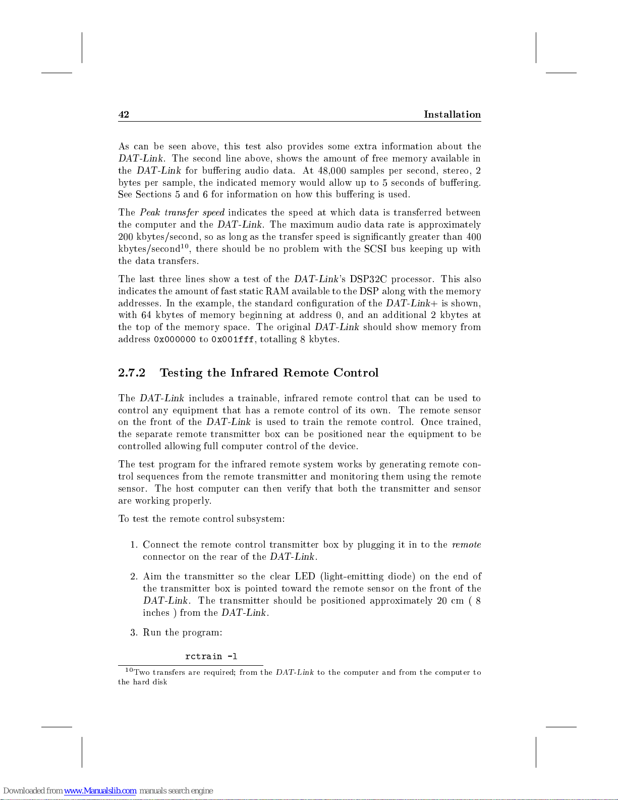
42 Installation
As can be seen above, this test also provides some extra information about the
DAT-Link
the
bytes p er sample, the indicated memory would allow up to 5 seconds of buering.
See Sections 5 and 6 for information on how this buering is used.
The
the computer and the
200 kbytes/second, so as long as the transfer sp eed is signicantly greater than 400
kbytes/second10, there should b e no problem with the SCSI bus keeping up with
the data transfers.
. The second line ab ove, shows the amount of free memory available in
DAT-Link
Peak transfer speed
for buering audio data. At 48,000 samples per second, stereo, 2
indicates the speed at which data is transferred b etween
DAT-Link
. The maximum audio data rate is approximately
The last three lines showatest of the
indicates the amount of fast static RAM available to the DSP along with the memory
addresses. In the example, the standard conguration of the
with 64 kbytes of memory b eginning at address 0, and an additional 2 kbytes at
the top of the memory space. The original
address
2.7.2 Testing the Infrared Remote Control
The
control any equipment that has a remote control of its own. The remote sensor
on the front of the
the separate remote transmitter box can be positioned near the equipment to be
controlled allowing full computer control of the device.
The test program for the infrared remote system works by generating remote con-
trol sequences from the remote transmitter and monitoring them using the remote
sensor. The host computer can then verify that both the transmitter and sensor
are working properly.
To test the remote control subsystem:
0x000000to0x001fff
DAT-Link
1. Connect the remote control transmitter boxby plugging it in to the
connector on the rear of the
includes a trainable, infrared remote control that can be used to
DAT-Link
, totalling 8 kbytes.
is used to train the remote control. Once trained,
DAT-Link
DAT-Link
's DSP32C processor. This also
DAT-Link
DAT-Link
.
should show memory from
+isshown,
remote
2. Aim the transmitter so the clear LED (light-emitting diode) on the end of
the transmitter b oxispointed toward the remote sensor on the front of the
DAT-Link
inches ) from the
3. Run the program:
10
Two transfers are required; from the
the hard disk
. The transmitter should be p ositioned approximately 20 cm ( 8
rctrain -l
DAT-Link
.
DAT-Link
to the computer and from the computer to
Page 47
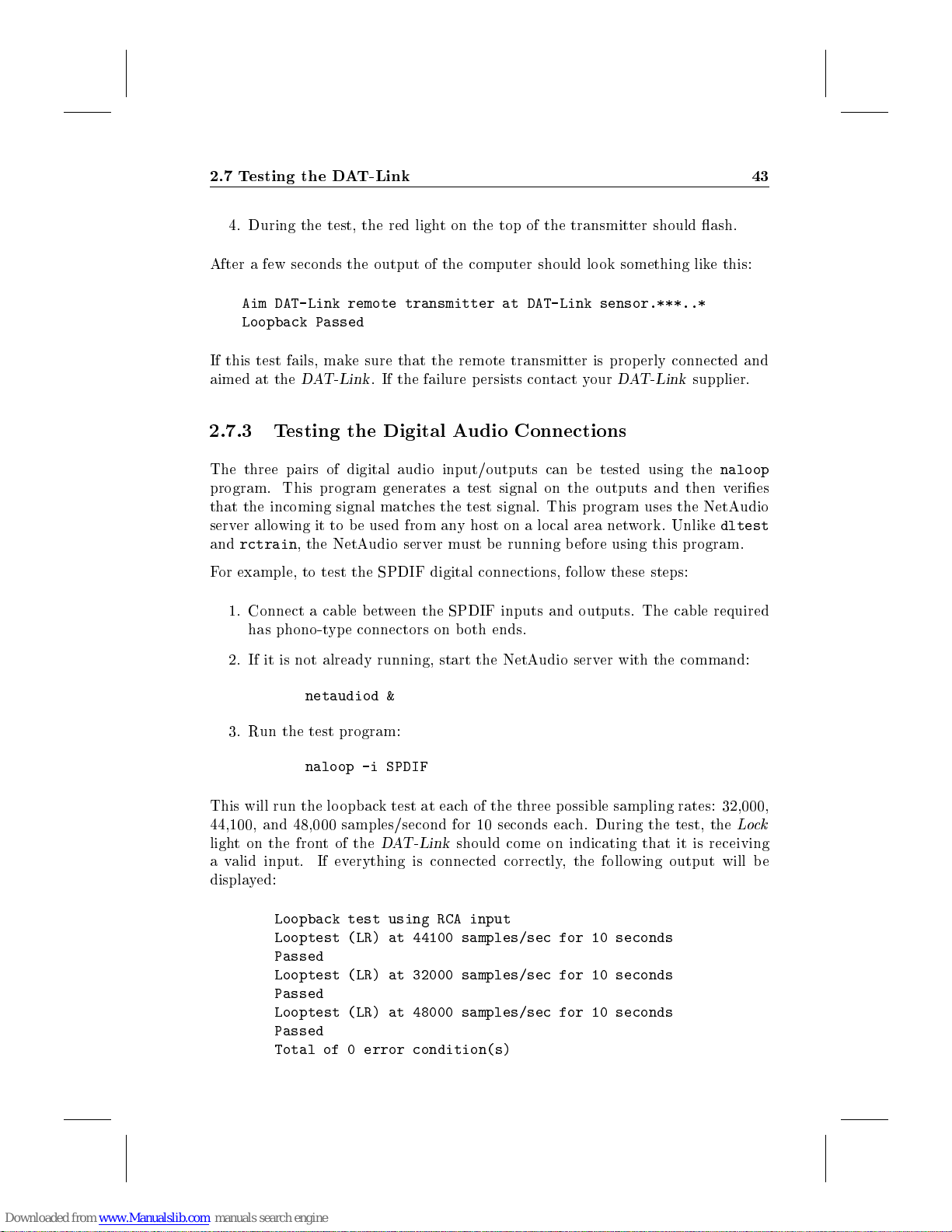
2.7 Testing the DAT-Link 43
4. During the test, the red light on the top of the transmitter should ash.
After a few seconds the output of the computer should look something like this:
Aim DAT-Link remote transmitter at DAT-Link sensor.***..*
Loopback Passed
If this test fails, make sure that the remote transmitter is prop erly connected and
aimed at the
2.7.3 Testing the Digital Audio Connections
DAT-Link
. If the failure p ersists contact your
DAT-Link
supplier.
The three pairs of digital audio input/outputs can be tested using the
program. This program generates a test signal on the outputs and then veries
that the incoming signal matches the test signal. This program uses the NetAudio
server allowing it to b e used from any host on a lo cal area network. Unlike
and
rctrain
For example, to test the SPDIF digital connections, follow these steps:
1. Connect a cable b etween the SPDIF inputs and outputs. The cable required
has phono-type connectors on b oth ends.
2. If it is not already running, start the NetAudio server with the command:
3. Run the test program:
This will run the loopback test at each of the three possible sampling rates: 32,000,
44,100, and 48,000 samples/second for 10 seconds each. During the test, the
light on the frontofthe
a valid input. If everything is connected correctly, the following output will be
displayed:
, the NetAudio server must be running before using this program.
netaudiod &
naloop -i SPDIF
DAT-Link
Loopback test using RCA input
Looptest (LR) at 44100 samples/sec for 10 seconds
Passed
Looptest (LR) at 32000 samples/sec for 10 seconds
Passed
Looptest (LR) at 48000 samples/sec for 10 seconds
Passed
Total of 0 error condition(s)
should come on indicating that it is receiving
naloop
dltest
Lock
Page 48
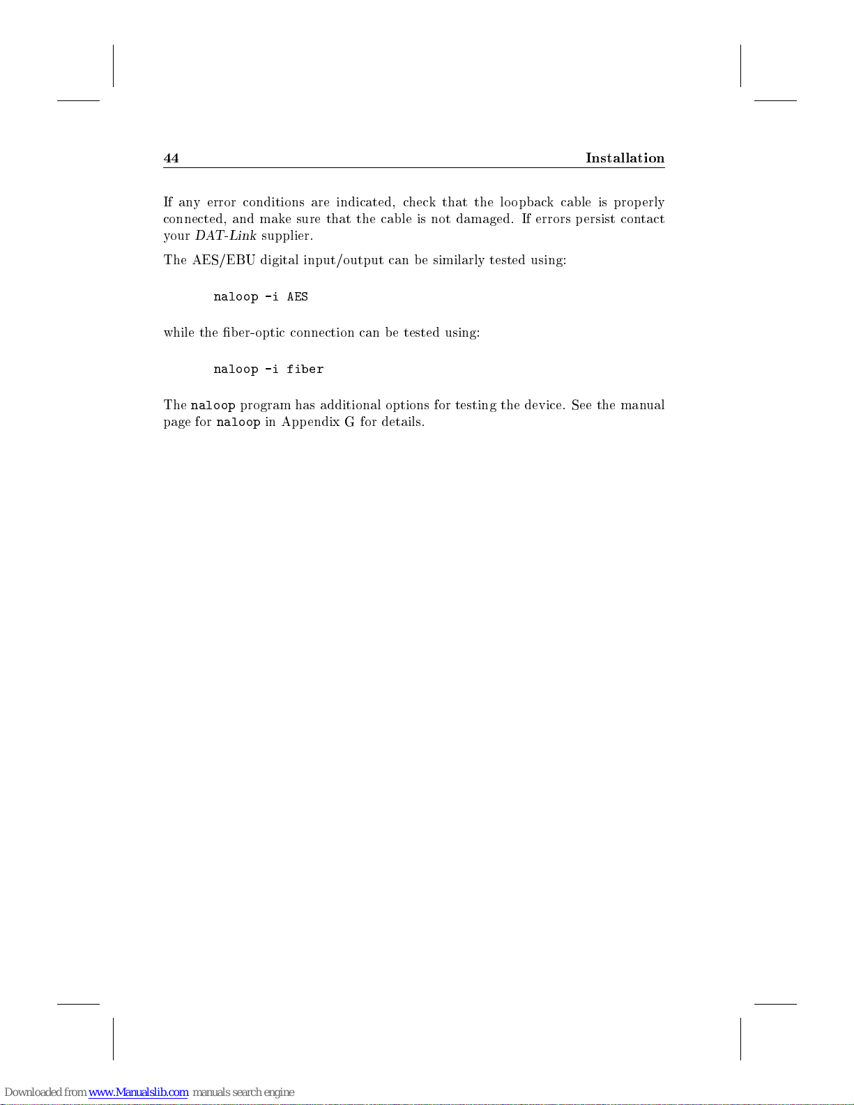
44 Installation
If any error conditions are indicated, check that the loopback cable is properly
connected, and make sure that the cable is not damaged. If errors persist contact
your
DAT-Link
The AES/EBU digital input/output can be similarly tested using:
naloop -i AES
while the b er-optic connection can be tested using:
naloop -i fiber
The
naloop
page for
naloop
supplier.
program has additional options for testing the device. See the manual
in Appendix G for details.
Page 49
Chapter 3
NetAudio Server
The NetAudio software consists of two main components, a server which manages
communication with the
operations as recording, playback, and remote control. This architecture is modelled
after the X Window System's server/client approach to providing graphical display
services.
The server for NetAudio provides the following functions:
Managementoflow-level communication with the DAT-Link.
Communication with clients on b oth the lo cal host and other hosts connected
via a local area network.
Multiple, simultaneous access to the status and control functions of the
Link
. For example, while one client is playing back an audio le, another can
be monitoring the levels and parameters, while another can modify settings
such as the overall gain.
DAT-Link
, and client programs which are used for such
DAT-
Exclusive access control to guarantee that data transfer to or from one client
won't be interrupted by another client or user on the system.
Logging of error messages to system logs using
Automatic restarting of the underlying daemon (
The following sections describ e how to start and use the server. However, once the
server is started, its presence will be invisible to the users. They will interact with
the
DAT-Link
using the client programs describ ed in the subsequent sections.
syslogd
netaudiod
.
) after a failure.
Page 50
46 NetAudio Server
3.1 Starting the Server
The server should be started on the computer to which the
before any of the client programs are used. Note that although the clients can be
run from anywhere on the network, the server must be run on the machine with
the
DAT-Link
command:
If all goes well, there will be no output from this program and it will exit immediately
after initializing. However a subprocess will have been created which will manage
communications with the DAT-Link. If there are any errors during the op eration of
naserver
Usually this will result in the messages b eing written to
/var/log/syslog
For testing, the NetAudio daemon can also be started for a single invocation with
error messages displayed on the terminal by using the command:
Once
naserver
described in Section 10.1, is a client which just displays the version numbers of the
server and the
is functional:
. In the typical environment, the server can be started with the
naserver
, they will b e logged using the system error logging facilities (
.
netaudiod
is running, client programs can be run. The program,
DAT-Link
naversion
hardware. It also provides a simple test that the server
DAT-Link
/usr/adm/messages
is connected
syslogd
naversion
or
).
,
More detailed information about the server's status can be obtained using the
nastatus
For non-standard congurations,
DAT-Link
the device created during installation will be
for a dierent unit, the-uoption can be given to
DAT-Links
and unit number. Chapter 9 describes use of multiple
Additional options to
included in App endix G.
For most installations, you will want the NetAudio always running on machines
with the
system administrator add a few lines to the system startup le, usually
/etc/rc.local
in
/usr/local
SUN workstation:
program describ ed in Section 10.2.
naserver
is connected to the host, it will normally be congured as unit 0, and
to b e used on the same machine, each with a separate NetAudio server
naserver
DAT-Link
, adding the following few lines to
connected. This is most easily accomplished by having the
to start
naserver
are described in the manual page for the program
. Assuming the
provides a few options. If only a single
/dev/datlink0
naserver
DAT-Links
DAT-Link
/etc/rc.local
. To start a server
. This allows multiple
in greater detail.
/etc/rc
programs were installed
would suce on a
or
Page 51
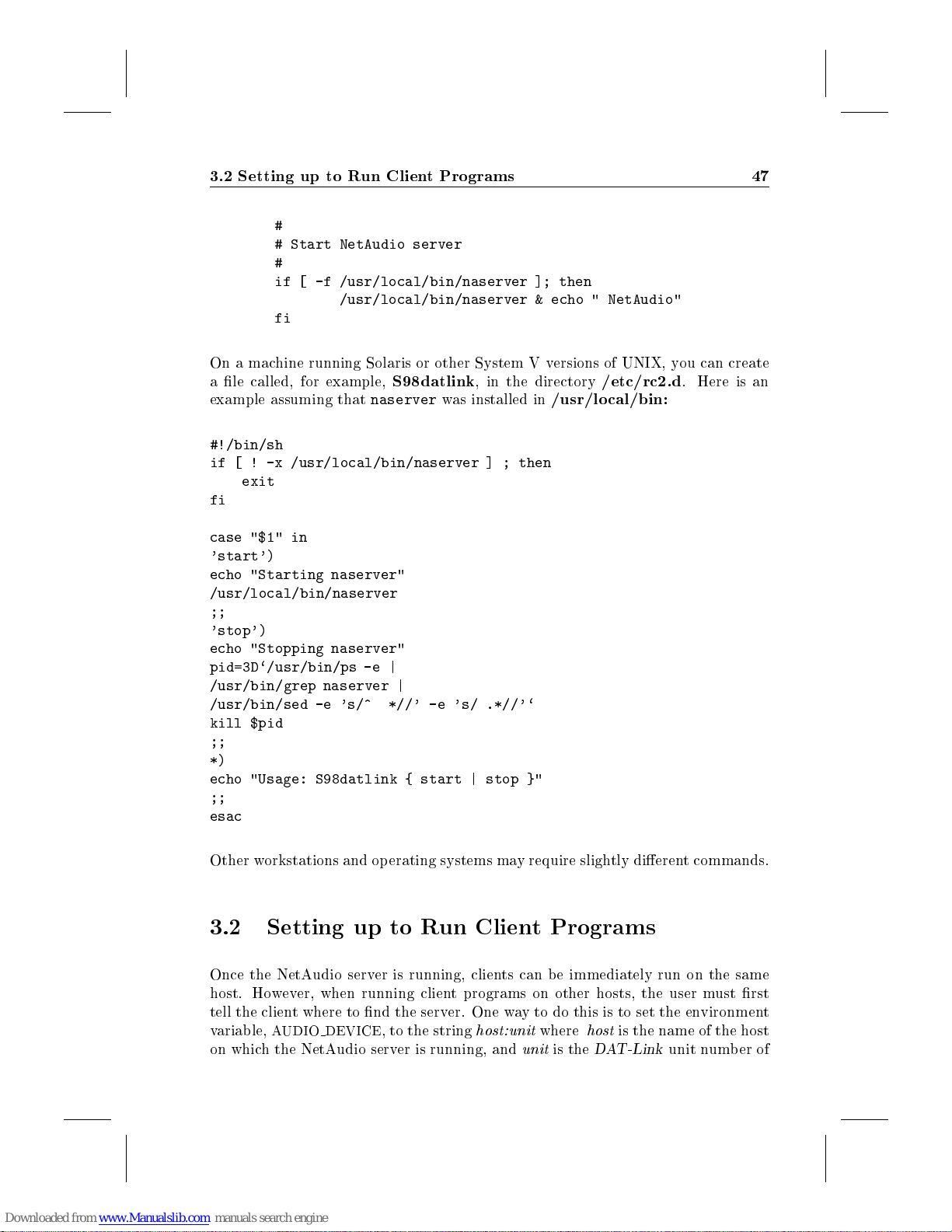
3.2 Setting up to Run Client Programs 47
#
# Start NetAudio server
#
if [ -f /usr/local/bin/naserver ]; then
/usr/local/bin/naserver & echo " NetAudio"
fi
On a machine running Solaris or other System V versions of UNIX, you can create
a le called, for example,
example assuming that
#!/bin/sh
if [ ! -x /usr/local/bin/naserver ] ; then
exit
fi
case "$1" in
'start')
echo "Starting naserver"
/usr/local/bin/naserver
;;
'stop')
echo "Stopping naserver"
pid=3D`/usr/bin/ps -e |
/usr/bin/grep naserver |
/usr/bin/sed -e 's/^ *//' -e 's/ .*//'`
kill $pid
;;
*)
echo "Usage: S98datlink { start | stop }"
;;
esac
S98datlink
naserver
, in the directory
was installed in
/etc/rc2.d
/usr/local/bin:
. Here is an
Other workstations and operating systems may require slightly dierent commands.
3.2 Setting up to Run Client Programs
Once the NetAudio server is running, clients can b e immediately run on the same
host. However, when running client programs on other hosts, the user must rst
tell the client where to nd the server. One way to do this is to set the environment
variable,
on which the NetAudio server is running, and
AUDIO DEVICE
, to the string
host:unit
unit
where
is the
host
is the name of the host
DAT-Link
unit number of
Page 52
48 NetAudio Server
interest, usually 0. For example, if you are using
setenv AUDIO_DEVICE foo:0
would instruct all client programs to use the unit 0 NetAudio server on the host
named
certain to connect to the same NetAudio server each time you log in.
Another way to specify which server to connect to is to use the-uoption available
in each NetAudio client program. Setting this option overrides any value set for
AUDIO DEVICE
snoopy
The
3.3 Programs that Bypass the Server
Although most of the commonly used
NetAudio server, there are a few that require a direct connection to the
These programs are the test program,
control training program,
must be run on the host with the
gram can directly communicate with the
temporarily suspend the NetAudio server while they are running. Any transfers in
progress will be aborted. When the program completes, the server will be resumed
with all internal settings, such as gain and sampling rate, reset to their defaults.
foo
. By adding the above
. For example, to check the
at unit 1, one could use the command:
naversion -u snoopy:1
naversion
client program is describ ed in Appendix 10.1.
setenv
rctrain
DAT-Link
(See Section 2.7.2 and 8.1). These programs
DAT-Link
command to your
dltest
DAT-Link
csh
, then the command:
.cshrc
DAT-Link
programs operate as clients to the
(See Section 2.7.1), and the remote
connected. Also, since only one pro-
version connected to host
at a time, these programs will
1
le, you can be
DAT-Link
.
3.4 Terminating the Server
If it becomes necessary to terminate the server, the
used. This program will rst request that the user conrms that the server should
be killed. Once killed,
other NetAudio programs can b e used. Note that
any access verication; any user on the local area network can terminate the server
with this command.
1
The equivalent forshor
naserver
ksh
users is \
nakillserver
must be restarted as describ ed above before any
nakillserver
AUDIO DEVICE=foo:0; export AUDIO DEVICE;
command can be
does not provide
".
Page 53
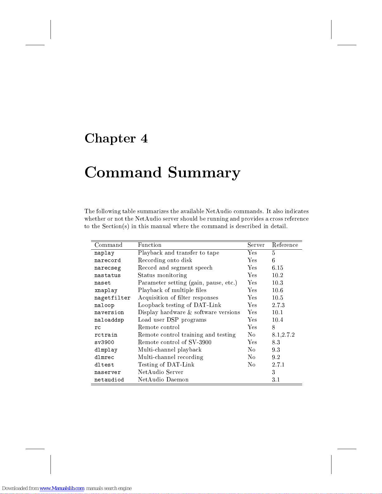
Chapter 4
Command Summary
The following table summarizes the available NetAudio commands. It also indicates
whether or not the NetAudio server should be running and provides a cross reference
to the Section(s) in this manual where the command is describ ed in detail.
Command Function Server Reference
naplay
narecord
narecseg
nastatus
naset
xnaplay
nagetfilter
naloop
naversion
naloaddsp
rc
rctrain
sv3900
dlmplay
dlmrec
dltest
naserver
netaudiod
Playback and transfer to tape Yes 5
Recording onto disk Yes 6
Record and segment speech Yes 6.15
Status monitoring Yes 10.2
Parameter setting (gain, pause, etc.) Yes 10.3
Playbackofmultiple les Yes 10.6
Acquisition of lter responses Yes 10.5
Loopback testing of DAT-Link Yes 2.7.3
Display hardware & software versions Yes 10.1
Load user DSP programs Yes 10.4
Remote control Yes 8
Remote control training and testing No 8.1,2.7.2
Remote control of SV-3900 Yes 8.3
Multi-channel playback No 9.3
Multi-channel recording No 9.2
Testing of DAT-Link No 2.7.1
NetAudio Server 3
NetAudio Daemon 3.1
Page 54
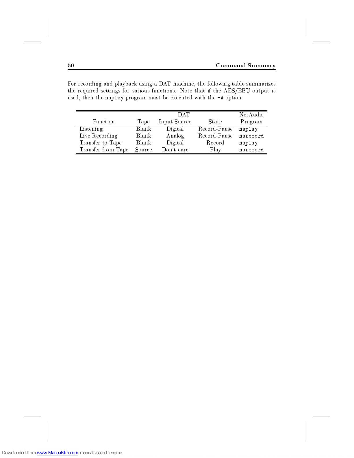
50 Command Summary
For recording and playback using a DAT machine, the following table summarizes
the required settings for various functions. Note that if the AES/EBU output is
used, then the
Listening Blank Digital Record-Pause
Live Recording Blank Analog Record-Pause
Transfer to Tape Blank Digital Record
Transfer from Tape Source Don't care Play
naplay
Function Tape Input Source State Program
program must be executed with the-Aoption.
DAT NetAudio
naplay
narecord
naplay
narecord
Page 55
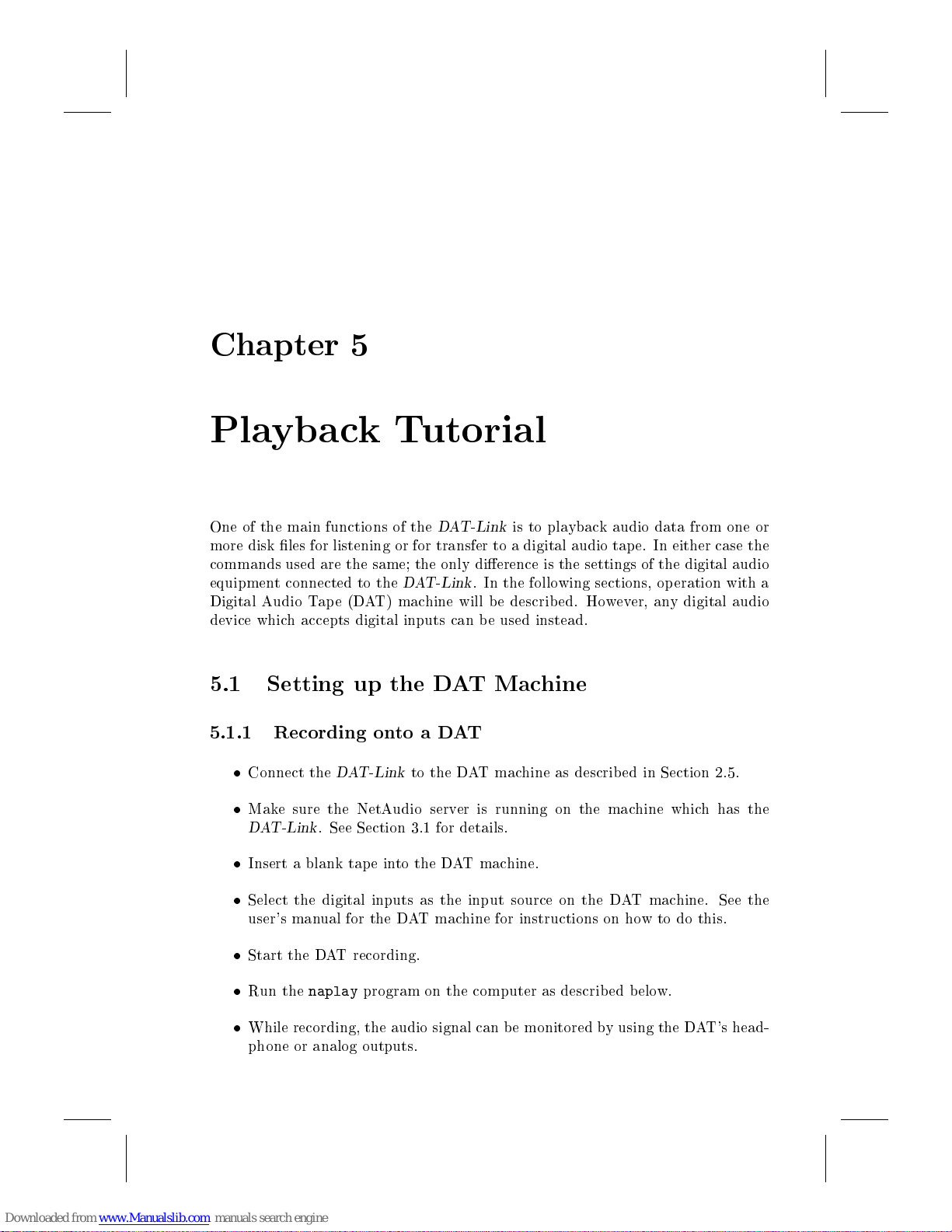
Chapter 5
Playback Tutorial
One of the main functions of the
more disk les for listening or for transfer to a digital audio tape. In either case the
commands used are the same; the only dierence is the settings of the digital audio
equipment connected to the
Digital Audio Tape (DAT) machine will be described. However, any digital audio
device which accepts digital inputs can be used instead.
5.1 Setting up the DAT Machine
5.1.1 Recording onto a DAT
Connect the
Make sure the NetAudio server is running on the machine which has the
DAT-Link
Insert a blank tape into the DAT machine.
Select the digital inputs as the input source on the DAT machine. See the
user's manual for the DAT machine for instructions on how to do this.
Start the DAT recording.
DAT-Link
. See Section 3.1 for details.
DAT-Link
DAT-Link
to the DAT machine as described in Section 2.5.
is to playback audio data from one or
. In the following sections, operation with a
Run the
While recording, the audio signal can b e monitored by using the DAT's head-
phone or analog outputs.
naplay
program on the computer as describ ed b elow.
Page 56
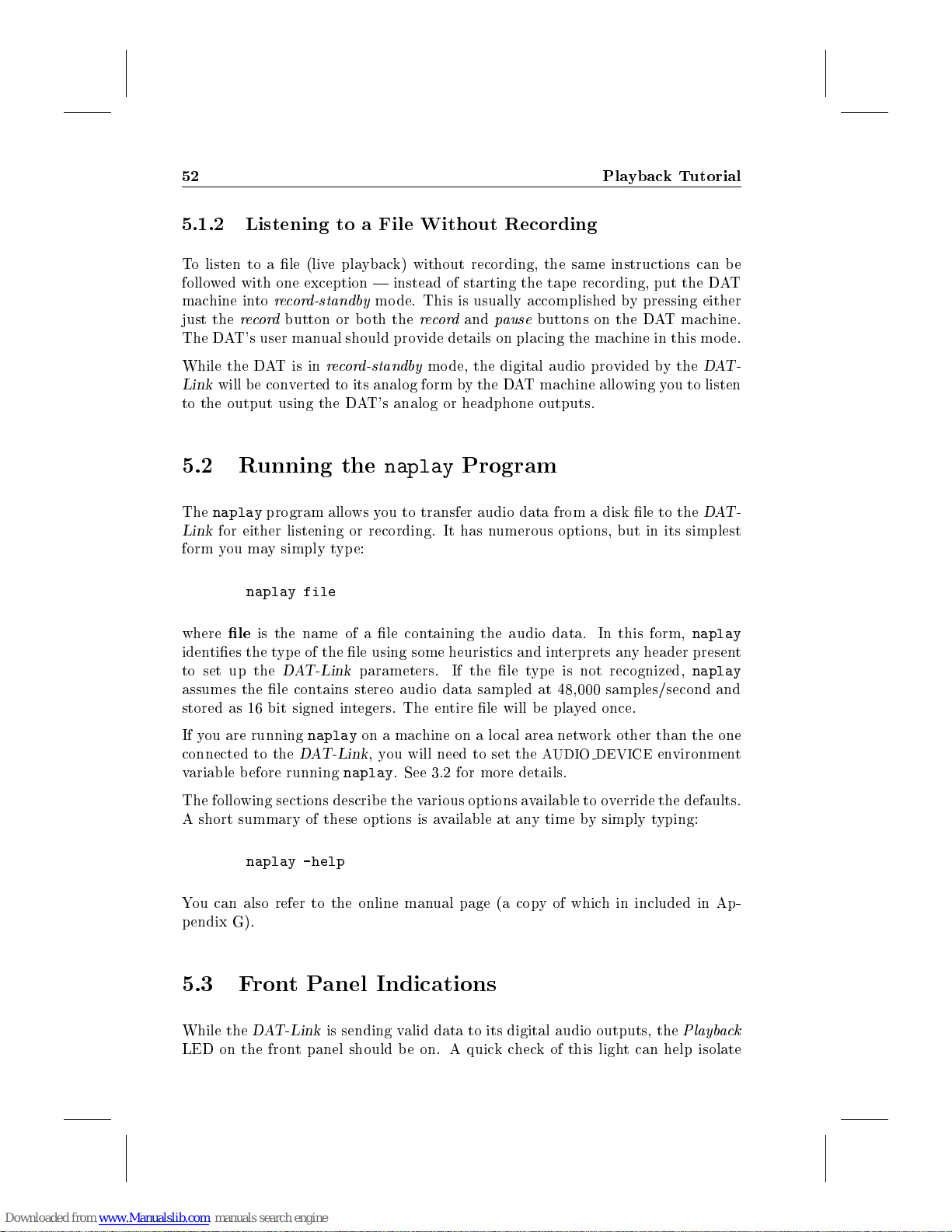
52 Playback Tutorial
5.1.2 Listening to a File Without Recording
To listen to a le (live playback) without recording, the same instructions can be
followed with one exception | instead of starting the tape recording, put the DAT
machine into
just the
The DAT's user manual should provide details on placing the machine in this mode.
record-standby
record
button or both the
mode. This is usually accomplished by pressing either
record
and
pause
buttons on the DAT machine.
While the DATisin
Link
will be converted to its analog form by the DAT machine allowing you to listen
to the output using the DAT's analog or headphone outputs.
5.2 Running the
The
naplay
Link
for either listening or recording. It has numerous options, but in its simplest
form you may simply type:
where
identies the type of the le using some heuristics and interprets any header present
to set up the
assumes the le contains stereo audio data sampled at 48,000 samples/second and
stored as 16 bit signed integers. The entire le will be played once.
If you are running
connected to the
variable before running
The following sections describ e the various options available to override the defaults.
A short summary of these options is available at any time by simply typing:
program allows you to transfer audio data from a disk le to the
naplay file
le
is the name of a le containing the audio data. In this form,
record-standby
DAT-Link
naplay
DAT-Link
mode, the digital audio provided by the
naplay
parameters. If the le type is not recognized,
on a machine on a lo cal area network other than the one
,you will need to set the
naplay
. See 3.2 for more details.
Program
AUDIO DEVICE
naplay
naplay
environment
DAT-
DAT-
naplay -help
You can also refer to the online manual page (a copy of which in included in Ap-
pendix G).
5.3 Front Panel Indications
While the
LED on the front panel should b e on. A quickcheck of this light can help isolate
DAT-Link
is sending valid data to its digital audio outputs, the
Playback
Page 57
5.4 Stereo or Mono 53
whether problems in playback are due to the connections between the host computer
and the
DAT-Link
or in the connection to the digital audio equipment.
On the
top Left and Right
relative to full-scale. This is often indicative that clipping is taking place. The
lower
exceeds -30 dB. The intensity of this LED is proportional to the playback level.
externally. This may be due to synchronization with external equipment or due to
explicit control using the
5.4 Stereo or Mono
Unless the le b eing played contains a header with additional information, the
naplay
nels interspersed. The rst sample in the le is for the left channel, followed by
the rightchannel, etc. If a dierent playback mode is required, the-ooption can
be used. The option should be followed by one of the words
stereo
and forces playback to either a single channel (left or right) or to both channels
(stereo or mono). The
in the le on both output channels.
For example,
DAT-Link
Level
The
Pause
program assumes that the le data contains stereo data with the twochan-
. These can be abbreviated to a single letter. The-ooverrides any defaults
+, there are a number of additional front-panel indications. The
Level
LED's indicate when the playback level exceeds -1 dB
LED's provide activity indicators that are lit when the playback level
LED is lit whenever the
naset
program.
mono
option plays back the same single-channel data stored
DAT-Link
+ is paused either internally or
left,right,mono
,or
naplay -oleft file
will transfer the single channel samples from the le to the left channel of the DAT
machine. The rightchannel will be silent.
5.5 Playing Part of a File
There are a number of options available for selecting a segment of a le for playback.
The-roption selects a range of the le to playback. The-rag is followed bya
range sp ecied as
are respectively the rst and last sample numbers to play. Either
be omitted in which case the beginning or end of the le is used.
naplay -r 8000:16000 file
will b egin playback at the 8,000th sample in the le and stop at the 16,000th sample.
start-end,start:end
,or
start:+count
, where
startorend
start
and
end
may
Page 58
54 Playback Tutorial
The playback time, in seconds, can be set using the-toption. For example, to
playback the rst 5 seconds of a le use:
naplay -t 5 file
Note that the-toption can not be used with the-roption. If neither option is
given, playback will continue until the end of the le.
Whether or not a duration is given on the command line, the
be interrupted at any time by hitting the interrupt character (usually control-C).
5.6 Repeating a Passage
The entire le or the passage selected using the above options can b e repeated any
number of times by using the-Roption. The number of repetitions is given as the
argumenttothe-Roption:
naplay -t 10 -R 3 file
results in 30 seconds of playback consisting of the rst 10 seconds of the le repeated
3 times. Note that there will be no space between the repetitions.
5.7 Sampling Rates
There are two sampling rates of imp ortance in playing back a le; the rate at which
samples are sent to the DAT machine, and the sampling rate of the le that is to
be played back.
5.7.1 DAT Sampling Rate
naplay
program can
Digital audio equipment usually accepts three possible sampling rates: 32,000,
44,100, or 48,000 samples/second. The most common rate is 48,000 samples/second
and this is the default for the
compact disks or pre-recorded tap es.
The digital audio sampling rate can b e changed using the-Soption to
playback a le such that the DAT records it at 44,100 samples/second use:
naplay -S 44100 file
Note that it is assumed that the le being sent to the DAT is sampled at the
same rate as chosen with the-Soption. In this case,
naplay
program. The 44,100 is usually only used for
naplay
le
should contain audio
. To
Page 59
5.7 Sampling Rates 55
data sampled at 44,100 samples/second. Also note that whenever the DAT rate is
changed, the DAT machine may take a few seconds to lo ck to the new rate. Some
machines may cut o the b eginning of the audio output or generate a click when this
happens. Subsequent playback at the same rate should not exhibit this problem.
There are also some special settings of the-Soption used to synchronize the output
with an external source. These are invoked by prexing the DAT sampling rate with
a letter as follows:
A:
Select the AES/EBU input connector as the clo ck source. Outgoing digital
audio data will be at the same sampling rate as the incoming signal.
SorR:
F:
E:
G:
For theA,S,orFsettings, a valid digital audio signal such as is generated byaCD
player or DAT machine must be applied to the selected input. Note that a DAT
sampling rate must still be specied, even though an external clock will be used.
This is necessary is order for
required.
To set the external or sync1input as the clock source, assuming the input will be
nominally 44,100 samples/second, you would use:
The external clock or sync connector can also be used as a clock source instead
of input. When the letterGis specied before the DAT sampling rate, on the
naplay
For example,
Select the SPDIF (IEC Type II) input as the clock source.
Select the b er-optic input as the clock source.
Use the
Generate clo cks on the external clock or sync connector.
Word ClockorSync
source for the sampling clock.
naplay -S E44100 file
command line, a clock is output on the external clock or sync connector.
connector on the rear of the
naplay
to properly design a sample-rate converter, if
DAT-Link
as the
naplay -S G48000 file
uses the internal oscillator to generate a 48,000 samples/sec clock and outputs it on
the external clo ck connector. This allows other devices or
o a master device as described in Section 9.1. External clo ck input and output
can also be controlled by the
1
DAT-Link
+version 1.6 and newer use a Sync connector, prior models used a clock connector
naset
program describ ed in Section 10.3.
DAT-Links
to be slaved
Page 60
56 Playback Tutorial
5.7.2 File Sampling Rate
If the le stored on the computer is not at the same sampling rate as that which
will be used by the DAT machine, a sampling-rate conversion op eration must be
performed. This is done automatically in real time by the
built-in digital signal processor. To invoke a conversion, you need only specify
the sampling rate of the le using the-soption. As an example, assume you have
a mono le of speech stored on disk that was sampled at 8,000 samples/second.
Further, assume you wish to record this le onto both channels of a DAT at 44,100
samples/second. The appropriate command would b e:
naplay -omono -s 8000 -S 44100 file
The
-omono
sampled at 8,000 samples/second and the
generate audio data at 44,100 samples/second. To perform this command the
Link
will p erform a digital resampling operation which will result in some low-pass
ltering of the audio signal. See Chapter 7 for more information on the eects of
this conversion.
5.8 File Formats
option selects monophonic playback, the
-S 44100
instructs the
-s 8000
DAT-Link
means the le is
using its
DAT-Link
to
DAT-
In the ab ove sections wehave assumed the le being used contains just audio data
stored as 16 bit signed integers. By default
type by using various heuristics. If these fail, a warning message will b e printed and
the
raw
format will be used. Other formats are available by using the-foption
followed by a format name. A full list of possible formats can be displayed by
typing:
naplay -f help
Appendix B.1 describes the encoding of each format.
In addition, to the overall le format, the type of data encoding can be specied
using the-eoption. The valid encoding choices are:
Linear:Direct linear encoding of the data as signed integers. The precision of the
values defaults to 16 bits/sample, but can be changed using the-poption
described below. This is the default enco ding.
IEEE:IEEE oating point format using 4 bytes/sample.
ALaw:One byte per sample, A-law companded data.
uLaw:One byte per sample, mu-law companded data.
naplay
will attempt to deduce the le
Page 61
5.9 Playing Multiple Files 57
For example, the command:
naplay -e ieee file
plays back a le of oating pointnumbers. For the linear encoding, the number of
bits/sample can also be sp ecied using the-poption. To playback a le containing
20-bit samples use:
naplay -p20 file
Note that the data is assumed to be packed such that every pair of samples will
occupy 5 bytes. Valid choices of the precision are 4, 8, 12, 16, 20, 24, 28, or 32
bits/sample.
Note that not all combinations of the-f,-e, and-poptions are valid. Certain le
formats supp ort only particular encodings and precisions. Attempting to playback
a le with an enco ding or precision dierent from that with whichitwas recorded
will either be rejected or result in incorrect playback. Also, if sample-rate conversion
is b eing used, the software currently supports 16 bit/sample, linear encoding only.
5.9 Playing Multiple Files
Multiple les maybeplayed without anyintervening gap by listing each le on the
command line:
naplay file1 file2 file3
The same settings (sampling rate, precision, etc. ) are used for playback of each
le. If a space is required between each le, then additional les containing zero es
can be created and inserted between each le. For example, for stereo playback
at 48,000 samples/second, the following commands will create a le containing one
second of silence and insert it b etween each le2:
dd if=/dev/zero bs=4 count=48000 of=gap
naplay file1 gap file2 gap file3
5.10 Using Standard Input
If no lename is given on the command line, then the audio input data is taken
from the standard input. This allows another program which generates sampled
2
/dev/zero
does not exist on all versions of
UNIX
Page 62
58 Playback Tutorial
data to be connected to the
For example, if
a test tone can be output on the left channel using:
The playback will continue until either the
the program is interrupted. Note that the-r,-t, and-Roptions are not available
when standard input is used.
5.11 Channel Status and User Bits
In addition to audio data, the connection between the
audio equipment also carries some additional information known as
bits
and
channel status bits for that are appropriate for the chosen values of the other options,
assuming a consumer digital audio device is connected. If you are using professional
equipment with the AES/EBU connectors on the
be given the-Aoption. This causes some subtle modications to the channel status
bits that are required by the professional standards.
For users that wish to exercise greater control over the channel status and user bits,
naplay
a le. This le can be edited using any text editor. It's format is described in
Appendix B.4.
has an option,-c, which instructs it to read the control information from
sine
is a program which generates a sampled-data sine-wave, then
sine | naplay -ol
user bits
. By default,
naplay
naplay
program without creating an intermediate le.
sine
program stops generating data or
DAT-Link
zeroes all of the user bits and generates
DAT-Link
and the digital
, then
naplay
channel status
should
5.12 Starting and Stopping the DAT Machine
The
naplay
stop the DAT recorder automatically. By running
DAT-Link
playback has completed, the DAT machine will b e stopped.
Before this option can be used, it is necessary to set up the
control facility as describ ed in Chapter 8. Also, the
must b e set to the name of the device to be controlled. To start the DAT machine
the
naplay
Between the RECORD and PLAY commands, the six second pause gives the DAT
machine time to enter record mo de. When playback is nished the program issues
a STOP command.
program also provides an option that allows the
naplay
will start the DAT machine recording b efore beginning playback. After
program issues the following remote commands:
STOP - RECORD - <6 second pause> - PLAY
DAT-Link
with the-aoption, the
DAT-Link
DL RC
environmentvariable
to start and
's remote
Page 63
5.13 Buering of Audio Data 59
5.13 Buering of Audio Data
This section describ es how the
formation may be useful in some interactive applications where it is importantto
control latencies when sound les are played back. It may also be necessary to
modify the buer settings to avoid underrun errors when transferring audio les
across a network.
The
DAT-Link
buer audio data sent from the host computer. This buering is necessary to allow
the host computer to be used by multiple users and tasks without creating gaps
in the playback. It does, however, occasionally create some delays and unexp ected
behavior.
When the host computer begins sending audio data to the NetAudio server for
playback, the
audio outputs. It instead stores the data in its internal buer. Playback does not
actually commence until one of the following situations o ccur:
1. Enough data for one second of playback has been transferred. The amount
of buering may be changed by using the
Section 5.14.
2. The host computer nishes sending the audio data.
Once playback begins, the host computer must continue to send audio data to the
DAT-Link
drains completely before the host computer is nished playing back a le, an error
is returned and playback is stopped. Gaps will never be inserted into the playback.
The buer utilization can be monitored by the
Section 10.2.
contains an internal buer of approximately 2 Mbytes that is used to
DAT-Link
suciently quickly to keep the buer from becoming empty. If the buer
does not immediately b egin sending the data to its digital
DAT-Link
buers audio data internally. This in-
bufferTime
nastatus
option described in
command described in
The main eect of the buering on
0.5 seconds between the time the
begins. The actual delay time dep ends on the sp eed of the host computer, the SCSI
bus transfer speed, and the network load if the
remote machine.
For applications where ner control over the buering is required, custom programs
can be written using the subroutine library describ ed in Section 12 and Appendix
G.
5.14 Customizing the Conguration
Many of the command line options, as well as additional options can be sp ecied in
the users
.datlinkrc
naplay
naplay
le in their home directory. The format of this le is described
is that there is a delay of approximately
command is issued and when sound output
naplay
command is issued on a
Page 64
60 Playback Tutorial
Table 5.1: Options Available for
Option
naplay.AutoStart Bool No Automatically start & stop
naplay.buerTime Float 1.0 Duration of audio data, in
naplay.Consumer Bool Yes Yes to generate consumer
naplay.lter.resp.nn.
naplay.lter.stopband.atten Float 90 Attenuation, in dB, of
naplay.lter.atten.nn.
mm
mm
Type Default Description
String Null If non-Null, the specication
Float 90 Alternate method of spec-
naplay
DAT machine
seconds, to buer before be-
ginning playback. It may
be necessary to increase this
value to avoid underruns dur-
ing playback over a heavily-
loaded network.
channel status info, No to
generate professional channel
status.
of lter response for sample-
rate converter which con-
verts from
ples/second. See Chapter
7 for details on using this
option.
sample-rate converter's
anti-aliasing stopband.
ifying stopband attenuation
for specic sampling rate
conversions.
nntomm
sam-
in Appendix B.3. The options used by
Note that versions of
links. For example, to create a version of
lters, rst create a link to the
following line to your
phplay.Resampler.filter.resp*: 0@-90,400@0,3400@0,4000@-90
This option will be used only when the play program is invoked with the name
phplay
the
. Other options can similarly be used to create other customized versions of
DAT-Link
programs.
naplay
with dierent defaults can be created by using symbolic
.datlinkrc
naplay
naplay
le:
are listed in Table 5.1.
naplay
program called
which uses telephone bandwidth
phplay
. Then add the
Page 65
Chapter 6
Recording Tutorial
This chapter describ es how to use the
your computer. The audio data may come from a DAT machine, a CD player, or any
other audio device connected to one of the
recordings can b e made by using a DAT machine as a analog-to-digital converter
as describ ed below.
6.1 Setting up the DAT Machine
6.1.1 Transferring Audio From a DAT Tape to a Disk File
Connect the
Make sure the NetAudio server is running on the machine which has the
DAT-Link
Insert the tap e into the DAT machine.
Run the
Start the DAT playing.
While playing, the audio signal can be monitored by using the DAT's head-
phone or analog outputs.
DAT-Link
. See Section 3.1 for details.
narecord
to the DAT machine as described in Section 2.5.
program on the computer as describ ed b elow.
DAT-Link
DAT-Link
to capture audio onto a disk le on
's digital audio inputs. Live
6.1.2 Transferring Audio From a CD to a Disk File
Connect the
DAT-Link
to the CD player as described in Section 2.5.
Page 66
62 Recording Tutorial
Make sure the NetAudio server is running on the machine which has the
DAT-Link
Insert the CD into the CD player.
Run the
Start the CD playing.
While playing, the audio signal can be monitored by using the CD's headphone
or analog outputs.
6.1.3 Making a Live Recording
To record an analog signal directly onto the hard disk, you can use a DAT machine
in
record-standby
Connect the
Make sure the NetAudio server is running on the machine which has the
DAT-Link
. See Section 3.1 for details.
narecord
mode:
. See Section 3.1 for details.
program on the computer as describ ed b elow.
DAT-Link
to the DAT machine as described in Section 2.5.
Insert a blank tap e into the DAT machine. Most machines require a blank
tape to be inserted to allow the DAT machine to enter
Set the DAT machine's input source to its analog inputs.
Connect the analog input source, such as a pre-amplier or microphone to the
DAT's analog input(s).
Place the DAT machine in
by pressing either just the
on the DAT machine. The DAT's user manual should provide details on
placing the machine in this mo de.
Run the
Start the analog input (i.e. if using a microphone, begin talking).
While recording, the audio signal can b e monitored by using the DAT's head-
phone or analog outputs.
If a duration was not given when
a few seconds after you are nished recording.
narecord
program on the computer as describ ed b elow.
record-standby
record
button or b oth the
narecord
mode. This is usually accomplished
was started, interrupt the program
record-standby
record
and
pause
mode.
buttons
Page 67
6.2 Running the
narecord
Program 63
6.2 Running the
The
narecord
disk le. It has numerous options, but in its simplest you may simply type:
where
le
accepts stereo audio data and stores it as 16 bit signed integers. Recording will con-
tinue until the program in interrupted using the
control-C). Note that if recording is interrupted, the end of the recording maybe
truncated { leave a few extra seconds after the signal of interest has ended b efore
interrupting
If you are running
connected to the
variable before running
The following sections describ e the various options available to override the defaults.
A short summary of these options is available at any time by simply typing:
You can also refer to the online manual page (a copy in included in App endix G).
program allows you to transfer audio data from the
narecord file
is the name of a le containing the audio data. In this form,
narecord
narecord -help
.
narecord
DAT-Link
narecord
on a machine on a lo cal area network other than the one
,you will need to set the
narecord
. See Section 3.2 for more details.
Program
UNIX
interrupt character (usually
AUDIO DEVICE
DAT-Link
environment
to a
narecord
6.3 Front Panel Indications
While the
the
when to b egin when making a live recording. In addition, the
also b e on, indicating that the
On the
top Left and Right
to full-scale. This is often indicative that clipping is taking place. The lower
LED's provide activity indicators that are lit when the record level exceeds -30
dB. The
externally. This may be due to synchronization with external equipment or due to
explicit control using the
6.4 Selecting the Input Source
Since there are three p ossible sources for incoming digital audio data, the user must
select which input is active using the-ioption. The p ossible arguments to the
Record
DAT-Link
DAT-Link
LED on the front panel should be on. This light can be used to tell
Pause
is accepting audio data from one of its digital audio outputs,
Lock
LED should
DAT-Link
+, there are a number of additional front-panel indications. The
Level
LED's indicate when the record level exceeds -1 dB relative
LED is lit whenever the
naset
program's pause control.
is receiving a valid digital input.
DAT-Link
+ is paused either internally or
Level
Page 68
64 Recording Tutorial
option are:
AES:Select the AES/EBU input connector as the source.
SPDIForRCA:Select the SPDIF (IEC Type II) input as the source.
FIBER:Select the b er-optic input as the source.
The abovechoices may be abbreviated to a single character. If the-ioption is not
provided, then the SPDIF input is used.
6.5 Stereo or Mono
By default, the
le, with the twochannels interspersed. The rst sample in the le is for the left
channel, followed by the right channel, etc. If monophonic recording is required
either the
narecord -oright file
will store only the rightchannel into the le. The incoming left channel audio will
be discarded. Stereo input can b e explicitly specied on the command line using
-ostereo
and stereo respectively.
6.6 Specifying the Recording Duration
The-nand-toptions select the duration of the recording, in samples or seconds
respectively. If neither option is used, recording will continue until the program is
interrupted. For example, to record 5 seconds of audio into a le use:
. These options can be abbreviated to
narecord -t 5 file
narecord
-oleftor-oright
program stores both channels of the stereo data in a
options can be used. For example,
-ol,-or
, and
-os
for left, right,
6.7 Sampling Rates
There are two sampling rates of importance in recording audio; the rate at which
samples are sent from the DAT machine, and the sampling rate of the le that is
being created.
Page 69
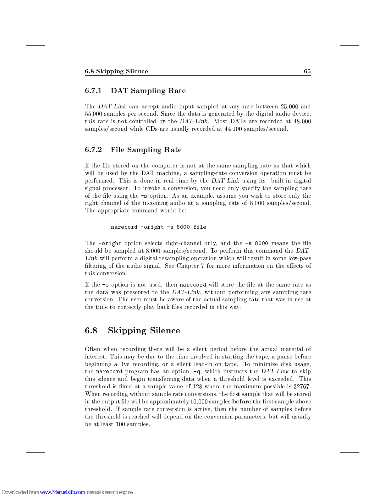
6.8 Skipping Silence 65
6.7.1 DAT Sampling Rate
The
DAT-Link
55,000 samples per second. Since the data is generated by the digital audio device,
this rate is not controlled by the
samples/second while CDs are usually recorded at 44,100 samples/second.
6.7.2 File Sampling Rate
If the le stored on the computer is not at the same sampling rate as that which
will be used by the DAT machine, a sampling-rate conversion op eration must be
performed. This is done in real time by the
signal processor. Toinvoke a conversion, you need only sp ecify the sampling rate
of the le using the-soption. As an example, assume you wish to store only the
right channel of the incoming audio at a sampling rate of 8,000 samples/second.
The appropriate command would b e:
The
-oright
should be sampled at 8,000 samples/second. To perform this command the
Link
will p erform a digital resampling operation which will result in some low-pass
ltering of the audio signal. See Chapter 7 for more information on the eects of
this conversion.
can accept audio input sampled at any rate between 25,000 and
DAT-Link
narecord -oright -s 8000 file
option selects right-channel only, and the
. Most DATs are recorded at 48,000
DAT-Link
using its built-in digital
-s 8000
means the le
DAT-
If the-soption is not used, then
the data was presented to the
conversion. The user must be aware of the actual sampling rate that was in use at
the time to correctly play back les recorded in this way.
6.8 Skipping Silence
Often when recording there will be a silent period before the actual material of
interest. This may b e due to the time involved in starting the tape, a pause before
beginning a live recording, or a silent lead-in on tape. To minimize disk usage,
the
narecord
this silence and begin transferring data when a threshold level is exceeded. This
threshold is xed at a sample value of 128 where the maximum possible is 32767.
When recording without sample rate conversions, the rst sample that will be stored
in the output le will be approximately 10,000 samples
threshold. If sample rate conversion is active, then the number of samples b efore
the threshold is reached will depend on the conversion parameters, but will usually
be at least 100 samples.
program has an option,-q, which instructs the
narecord
DAT-Link
will store the le at the same rate as
, without performing any sampling rate
before
DAT-Link
the rst sample above
to skip
Page 70
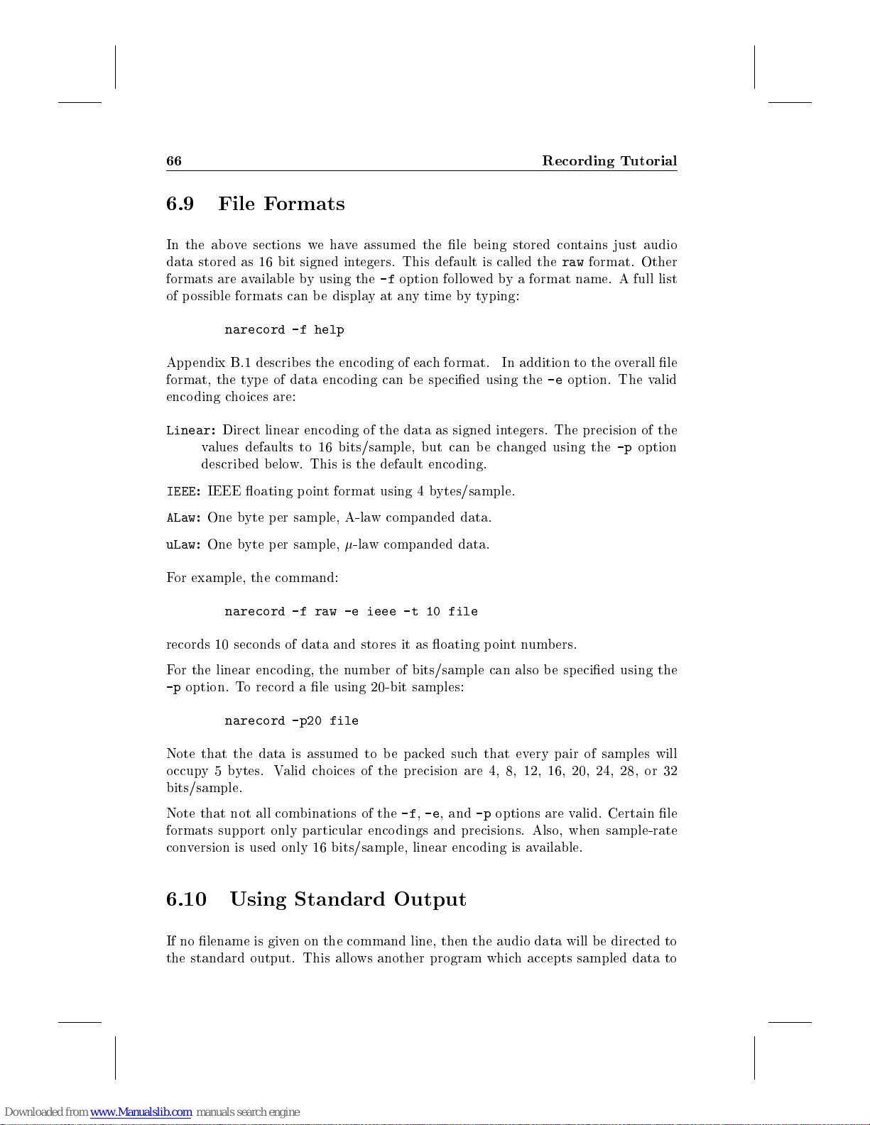
66 Recording Tutorial
6.9 File Formats
In the ab ove sections we have assumed the le being stored contains just audio
data stored as 16 bit signed integers. This default is called the
formats are available by using the-foption followed by a format name. A full list
of possible formats can be displayatany time bytyping:
narecord -f help
Appendix B.1 describes the enco ding of each format. In addition to the overall le
format, the type of data enco ding can be sp ecied using the-eoption. The valid
encoding choices are:
Linear:Direct linear encoding of the data as signed integers. The precision of the
values defaults to 16 bits/sample, but can be changed using the-poption
described below. This is the default enco ding.
IEEE:IEEE oating point format using 4 bytes/sample.
ALaw:One byte per sample, A-law companded data.
uLaw:One byte per sample,-law companded data.
raw
format. Other
For example, the command:
narecord -f raw -e ieee -t 10 file
records 10 seconds of data and stores it as oating pointnumbers.
For the linear encoding, the number of bits/sample can also be sp ecied using the
-p
option. To record a le using 20-bit samples:
narecord -p20 file
Note that the data is assumed to be packed such that every pair of samples will
occupy 5 bytes. Valid choices of the precision are 4, 8, 12, 16, 20, 24, 28, or 32
bits/sample.
Note that not all combinations of the-f,-e, and-poptions are valid. Certain le
formats support only particular encodings and precisions. Also, when sample-rate
conversion is used only 16 bits/sample, linear encoding is available.
6.10 Using Standard Output
If no lename is given on the command line, then the audio data will be directed to
the standard output. This allows another program which accepts sampled data to
Page 71
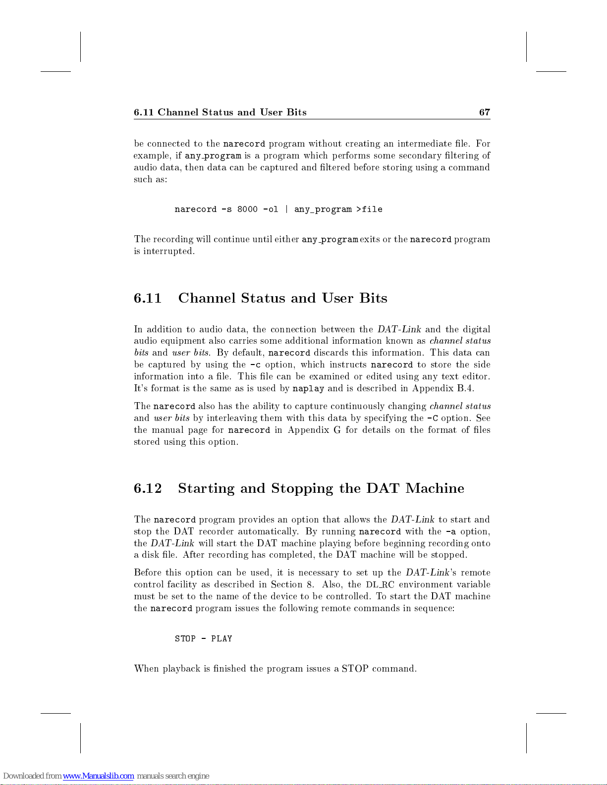
6.11 Channel Status and User Bits 67
be connected to the
example, if
audio data, then data can be captured and ltered before storing using a command
such as:
The recording will continue until either
is interrupted.
6.11 Channel Status and User Bits
In addition to audio data, the connection between the
audio equipment also carries some additional information known as
bits
and
be captured by using the-coption, which instructs
information into a le. This le can be examined or edited using any text editor.
It's format is the same as is used by
The
narecord
and
user bits
the manual page for
stored using this option.
any program
narecord -s 8000 -ol | any_program >file
user bits
narecord
. By default,
also has the ability to capture continuously changing
byinterleaving them with this data by specifying the-Coption. See
narecord
program without creating an intermediate le. For
is a program which p erforms some secondary ltering of
any program
narecord
in Appendix G for details on the format of les
discards this information. This data can
naplay
and is describ ed in App endix B.4.
exits or the
DAT-Link
narecord
narecord
to store the side
program
and the digital
channel status
channel status
6.12 Starting and Stopping the DAT Machine
The
narecord
stop the DAT recorder automatically. By running
the
DAT-Link
a disk le. After recording has completed, the DAT machine will b e stopped.
Before this option can be used, it is necessary to set up the
control facility as described in Section 8. Also, the
must b e set to the name of the device to be controlled. To start the DAT machine
the
narecord
When playback is nished the program issues a STOP command.
program provides an option that allows the
will start the DAT machine playing before beginning recording onto
program issues the following remote commands in sequence:
STOP - PLAY
DAT-Link
narecord
DL RC
to start and
with the-aoption,
DAT-Link
environment variable
's remote
Page 72
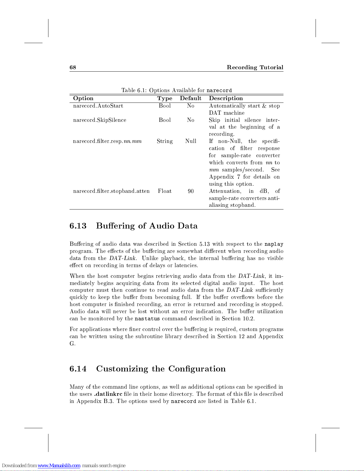
68 Recording Tutorial
Table 6.1: Options Available for
Option Type Default Description
narecord.AutoStart Bool No Automatically start & stop
narecord.SkipSilence Bool No Skip initial silence inter-
narecord.lter.resp.nn.
narecord.lter.stopband.atten Float 90 Attenuation, in dB, of
6.13 Buering of Audio Data
Buering of audio data was described in Section 5.13 with resp ect to the
program. The eects of the buering are somewhat dierent when recording audio
data from the
eect on recording in terms of delays or latencies.
DAT-Link
mm
. Unlike playback, the internal buering has no visible
String Null If non-Null, the speci-
narecord
DAT machine
val at the beginning of a
recording.
cation of lter resp onse
for sample-rate converter
which converts from
mm
samples/second. See
Appendix 7 for details on
using this option.
sample-rate converters anti-
aliasing stopband.
nn
naplay
to
When the host computer b egins retrieving audio data from the
mediately begins acquiring data from its selected digital audio input. The host
computer must then continue to read audio data from the
quickly to keep the buer from becoming full. If the buer overows before the
host computer is nished recording, an error is returned and recording is stopped.
Audio data will never be lost without an error indication. The buer utilization
can b e monitored by the
For applications where ner control over the buering is required, custom programs
can be written using the subroutine library describ ed in Section 12 and Appendix
G.
6.14 Customizing the Conguration
Many of the command line options, as well as additional options can be sp ecied in
the users
in Appendix B.3. The options used by
.datlinkrc
nastatus
le in their home directory. The format of this le is described
command describ ed in Section 10.2.
narecord
are listed in Table 6.1.
DAT-Link
DAT-Link
, it im-
suciently
Page 73
6.15 Speech Segmentation 69
Custom versions of the
that described in Section 5.14 for the
6.15 Speech Segmentation
When the
desirable to segment the sp eechinto words or segments. A front-end program for
the
As the sp eech is acquired by the
of each block of samples is also computed and passed to the
These energy computations allow
speech segment b egins and ends. Then, along with a le containing the acquired
data, a le containing pointers to each segment is written by
of the segmentation le is describ ed in App endix B.2.
The
accepted by
ments should be recorded before stopping. By default, one segment is recorded.
Note that the audio data is always stored using the
are not currently supported by
DAT-Link
narecord
narecseg
program called
program accepts the same-u,-a,-i,-o, and-soptions that are
narecord
narecord
is used to record or transfer sp eech sp eech signals, it is often
. In addition, the-ncan be used to specify how many seg-
program can b e created in a manner similar to
naplay
narecseg
DAT-Link
narecseg
narecseg
program.
provides this function.
's signal processor, the average energy
narecseg
to heuristically determine where each
narecseg
raw
le format. Other formats
.
. The format
program.
Page 74

70 Recording Tutorial
Page 75
Chapter 7
Sampling Rate Conversion
The
DAT-Link
the sampling rate used on the digital audio I/O's and any rate requested by the
user. Based on the requested rates, the software dynamically creates a conversion
program which makes optimal use of the DSP32C digital signal processor in the
DAT-Link
can b e chosen and obtained by the
Since the sample rate converters are generated dynamically, it is dicult to predict
the exact specications of the converter without looking a sp ecic examples (as will
be done in Section 7.1). However, the following information will be adequate for
most purp oses:
The converter contains a low pass lter with a stopband frequency of
where
provides real-time conversion during recording or playbackbetween
. Note that the conversions are not limited to integer fractions; any rate
fs1 and
DAT-Link
f
=
stop
fs2 are the input and output sampling rates.
min(
.
f
s
1;fs
2
)
2
The attenuation of the lter in the entire stopband, will b e approximately 90
dB. This value can be changed, as will be describ ed b elow.
The passband ripple should be about 0.0003 dB.
The lter will always be linear-phase.
The passband frequency will be chosen as high as possible, minimizing the
transition band. The exact frequency dep ends on the
conversion. In all cases, the software uses as much of the DSP32C's resources
as p ossible to obtain the sharpest possible lter cuto.
The
diculty
of the conversion is aected by the following:
diculty
of the requested
Page 76
72 Sampling Rate Conversion
Whether stereo or mono conversion is requested.
The magnitude of the input and output rates. For the same ratio, lower rates
are easier.
The ratio between the rates; medium ratios (2-5) are easiest. Ratios that are
very large may be constrained by the amount of memory available to the DSP.
Whether the ratio is an integer, a small fraction, or neither. Integer and
fractional ratios are marginally easier in most cases. If the ratio is very large
(or very small), then integer ratios will place less demand on the DSP.
7.1 Specications of Some Example Converters
The following table gives the specications for some example conversions. Note
that these specications are intended as an indication of p erformance only, due
to the dynamic methods used to allocate memory and resources, the exact results
you obtain may dier slightly. Exact impulse responses can be measured using the
nagetfilter
command describ ed in Section 10.5.
7.2 Changing the Filter Resp onse
By default, the software uses a maximally-sharp, lowpass lter as describ ed above.
However, it is p ossible to sp ecify an arbitrary lter response with the single proviso
that its passband frequency will never exceed that of the default lter. The desired
response is given as points on the magnitude resp onse curve. For example, the lter
shown in Figure 7.1 was specied using the string:
0@-90,200@-90,400@0,3400@0,3600@-90
The lter string should be entered in your
line:
naplay.filter*: 0@-90,100@0
would use a 100 Hz high-pass lter whenever
DAT-Link
Dierent lters can be sp ecied for dierent sample rate conversions by using an
option name of the form:
.
pgm.filter.irate.orate
.datlinkrc
naplay
le. For example, adding the
is used for output to the
Page 77
7.2 Changing the Filter Resp onse 73
Table 7.1: Example Sample-rate Converter Sp ecications
Number Sampling Rates Critical Frequencies Stopband Passband
of Input Output Passband Stopband Atten Ripple
Channels (Hz) (Hz) (dB) (dB)
1 8,000 44,100 3,882 4,000 90.9 0.0004
1 8,000 48,000 3,874 4,000 88.2 0.0004
1 8,001 48,000 3,874 4,000 90.9 0.0003
1 12,000 48,000 5,705 6,000 87.5 0.0004
1 44,100 8,000 3,690 4,000 91.2 0.0004
1 44,100 10,000 4,597 5,000 91.4 0.0004
1 44,100 48,000 15,422 22,050 91.4 0.0005
1 44,100 48,000 19,050 22,050 49.9 0.0309
1 48,000 8,000 3,752 4,000 90.0 0.0003
1 48,000 44,100 16,148 22,050 94.4 0.0003
1 48,000 44,100 19,785 22,050 53.8 0.0375
2 8,000 44,100 3,689 4,000 90.0 0.0005
2 8,000 48,000 3,640 4,000 89.8 0.0004
2 8,001 48,000 3,685 4,000 90.0 0.0005
2 12,000 48,000 5,279 6,000 88.3 0.0004
2 44,100 8,000 3,378 4,000 93.8 0.0003
2 44,100 10,000 4,124 5,000 94.5 0.0004
2 44,100 48,000 11,209 22,050 57.4 0.0528
2 48,000 8,000 3,488 4,000 90.0 0.0002
2 48,000 44,100 3,010 22,050 93.0 0.0002
2 48,000 44,100 13,274 22,050 58.3 0.0298
where
irate
is the input sampling rate1,
pgm
is the program for which this default applies. As with all defaults multiple
components can be matched by a \*" character. Thus the line:
*filter*8000: 0@-90,200@-90,400@0,3400@0,3600@-90
indicates that this lter (which is similar to a telephone connection) should be used
whenever the output rate is 8000 samples per second.
Note that ltering is performed only if sample-rate conversion is necessary. If no
sample-rate conversion is required, the exact samples are passed between the host
computer and the digital audio device.
1
input to the sampling rate converter, not necessarily input to the
orate
is the output sampling rate, and
DAT-Link
Page 78
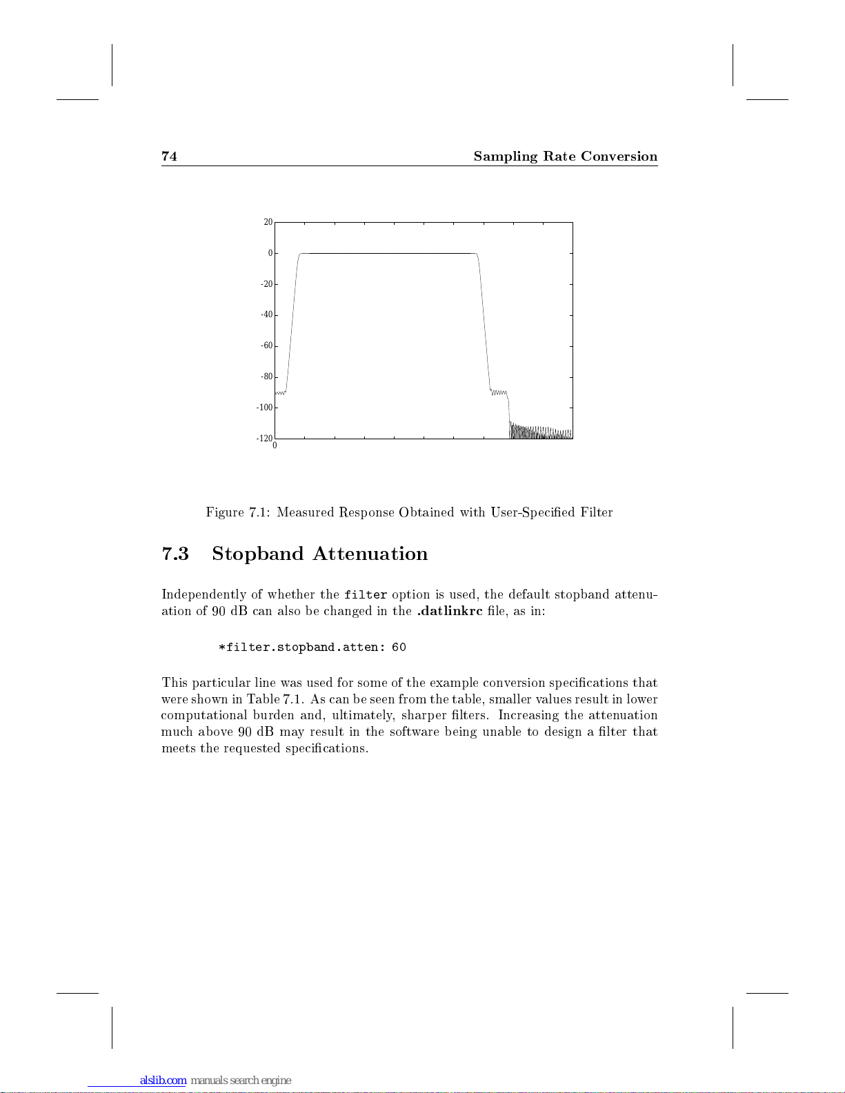
74 Sampling Rate Conversion
20
0
-20
-40
-60
Magnitude (dB)
-80
-100
-120
500 1000 1500 2000 2500 3000 3500 4000 4500 5000
0
Frequency (Hz)
Figure 7.1: Measured Resp onse Obtained with User-Specied Filter
7.3 Stopband Attenuation
Independently of whether the
ation of 90 dB can also be changed in the
*filter.stopband.atten: 60
This particular line was used for some of the example conversion specications that
were shown in Table 7.1. As can be seen from the table, smaller values result in lower
computational burden and, ultimately, sharp er lters. Increasing the attenuation
muchabove90dBmay result in the software being unable to design a lter that
meets the requested specications.
filter
option is used, the default stopband attenu-
.datlinkrc
le, as in:
Page 79
Chapter 8
Remote Control
The digital audio connections between the
digital audio device do not provide control over the machine. To allow the user
to control devices, the
sisting of an infrared sensor and transmitter. The handheld remote control for any
device can b e used to train the
the
DAT-Link
Commands to stop, start, rewind, etc. can then be added to programs or scripts
allowing greater automation of many functions. The remote control system is not
limited to control of digital audio devices. Any device that has an infrared remote
can be controlled by a computer using
can also be controlled by the
As distributed, the NetAudio software recognizes a number of devices. The known
machines can be listed using:
If your DAT machine is listed, you can skip the next section and proceed to Section
8.2. Otherwise, the following section describes how to train the
your device.
8.1 Training the Infrared Controller
using its remote control transmitter.
rc -l
DAT-Link
DAT-Link
provides a universal remote control system, con-
DAT-Link
DAT-Link
. The device can then be controlled by
DAT-Link
.
and a DAT machine or other
. Certain wired remote controls
DAT-Link
to control
Before using a new device to be controlled by the
be trained: it must be told how to generate the various commands suchas
STOP,REWIND
The program provided with the
, etc.
DAT-Link
DAT-Link
for training the remote control is called
, the
DAT-Link
must
PLAY
,
Page 80
76 Remote Control
rctrain
directly with the
is connected to the
rctrain
On completion of training, the server will resume.
Training can be run bytyping:
where
to be trained. For example, to train the
machine, you would type:
This will create a remote control description le for the DTC-75ES and prompt you
to do the following:
. Note that this program does not use the NetAudio server, it communicates
DAT-Link
DAT-Link
will temp orarily suspend its operation, ab orting any transfers in progress.
rctrain device operation
device
Aim the DTC-75ES's handheld remote control at the remote sensor on the
front panel of the
approximately 20 cm (8 inches).
Press and hold down the
rctrain
is the name of the device to be trained, and
rctrain DTC-75ES play
displays anOKmessage, the function will have been trained.
. Thus,
DAT-Link
rctrain
. Also, if the NetAudio server,
. The control should be held at a distance of
PLAY
must be run on the same machine that
PLAY
button on the remote control. When the
netaudiod
operation
function of a DTC-75ES DAT
, is running,
is the function
The ab ove procedure can be repeated for each button on the handheld remote
control. The naming of the buttons are arbitrary; any function can be programmed.
However, if you wish to use the-aoptions to the
the recommended command names listed in Table 8.1.
The format of the remote control descriptions is describ ed in Appendix B.5. If
you encounter problems with training the remote control, consult Section A.4 for
assistance.
8.2 Using the Remote Control
The remote control capabilities can be used in two ways: manually, by issuing
commands directly to the device, or automatically by using the
narecordornaplay
Sections 5.12 and 6.12.
Thercprogram allows you to manually control a device for which the remote has
been previously trained. It can be used inside shell scripts to automate rep etitive
procedures. Sincercuses the NetAudio server, it can be used from anywhere on a
. The automatic execution of commands was described in
naplay
and
narecord
-a
you should
options for
Page 81
8.2 Using the Remote Control 77
Table 8.1: Recommended Remote Control Function Names
Command Function
Stop Stop the DAT machine
Play Enter playmode
Pause Pause or release pause
Record Enter record mo de
Rewind Rewind tape
FF Fast-forward tap e
Skip Fwd Skip forward to next track
Skip Rev Skip backward to previous track
0
:::
9 Numeric entry
Open Open tape drawer
Close Close tap e drawer
Power Turn DATpower on or o
local area network. See Section 3.1 for details on starting and using the NetAudio
server.
To use therccommand you need to specify two things: the name of the device to b e
controlled (the same name used with
Both of these can be given on the command line as in:
rctrain
) and the function(s) to be executed.
rc -r DTC75-ES play
The name after the-roption gives the device name. The remaining words on the
command line are the commands to b e executed.
Multiple commands may be given in which case they will be executed sequentially:
rc -r DTC75-ES stop rewind play
If the same device is used repeatedly, its name may be omitted from the command
line by setting the environmentvariable,
then the commands:
setenv DL_RC DTC75-ES
rc stop rewind play
perform the same function as the previous example. The
set in your login script1. Note that this variable
options to
1
.login for
naplay
csh
and
narecord
users or .prole forshand
DL RC
. If you are using the c-shell (
DL RC
must
be set to use the automatic
since they do not provide an option to set the
ksh
users
variable maybe
csh
),
Page 82
78 Remote Control
device name on the command line. A list of available devices can be generated
using the command:
rc -l
A list of available commands can be displayed bytypingrcwith no arguments (or
just the-roption with a device name). Any of the commands listed can b e used as
arguments to therccommand. Note that the case of the command names is not
important.
8.3 ES-Bus Remote Control
Some DAT machines, notably the Panasonic SV-3900, have a serial remote control
based on the ES-Bus protocol. This device can be controlled by the
using the
DAT machines as well as extensive status monitoring. Up to 32 SV-3900's can be
controlled and monitored using a single
use of the SV-3900, refer to the manual page in Appendix G.
Note that, although the ES-Bus is an international standard, the use of ES-Bus
to control DAT machines has not been standardized. The
non-standard messages to control the SV-3900 DAT. Thus, it cannot b e used with
other ES-Bus devices. If you encounter another ES-Bus device which you would
like to control, contact your
sv3900
command. This provides comprehensive control over multiple
DAT-Link
DAT-Link
supplier for information about support.
. For details of connection and
sv3900
DAT-Link
program uses
8.4 Hard-wired Remote Controls
In addition to devices that have infrared remote controls or ES-Bus, certain classes
of devices whichhave a serial, hard-wired remote control input may b e controllable
by the
DAT-Link
devices, so the remote description le must be created manually. If a remote control
description le for the device of interest was included with the software distributed,
you will be able to use it to control the device. Otherwise, contact your
supplier for information on support of the device.
. However, it is not p ossible to train the
DAT-Link
to control these
DAT-Link
Page 83
Chapter 9
Using Multiple DAT-Links
Multiple
than 2 channels of audio input and output by using dierent SCSI ID's for each
device. Up to 7
present. Also, multiple hosts on the same network can have
In both cases all of the units can b e accessed from anywhere on the network.
To use multiple
described in Section 2.4. The device les created should b e called
/dev/datlink1,:::
with a dierent SCSI ID. The NetAudio server, described in the Chapter 3, uses
/dev/datlink0
set the unit number. For example,
will start a server which communicates with a single
instead of the default,
A NetAudio server must be started as described above for each
nected. As described in Section 3.1, this can be automated by placing commands
in the system startup le.
DAT-Link
netaudiod -u 1
devices may be connected to a single computer to provide more
DAT-Links
DAT-Links
, with each device le created to correspond with a
by default, but this can b e overridden by using the-uoption to
datlink0
can b e placed on a single SCSI bus if no other devices are
on a single host, each
.
DAT-Link
DAT-Link
DAT-Links
should b e installed as
connected.
/dev/datlink0
DAT-Link
using
datlink1
DAT-Link
con-
,
Client programs specify which
DIO DEVICE
program. Section 3.2 described these options in more detail.
environmentvariable or the setting of the-uoption available in each
DAT-Link
to use by either examining the
AU-
Page 84
80 Using Multiple DAT-Links
9.1 Synchronization
To record or playback audio les using multiple
nization come into play:
Sample-rate synchronization to guarantee that multiple units are op erating
at exactly the same rates.
Start-time synchronization to ensure that playback or recording b egin at the
same time.
Normally, both types of synchronization are required for playback. However, there
are some cases where multiple units may b e operated at dierent sampling rates.
One example is output of a low frequency control variable along with a wide-band
audio signal. In these cases only the start-time synchronization is required. Note,
however, that if the sample-rates of multiple units are not locked, it is not possible
to align the start-time with accuracy greater than plus or minus one sample.
Since the digital audio inputs to the
cannot enforce sample-rate synchronization during recording. The signals must b e
synchronized at their source by the external equipment. If the inputs are externally
synchronized at the same rate, then the
recorded from multiple units are exactly aligned. If the sources are not sample-rate
synchronized, then the start-time synchronization will only be accurate to plus or
minus one sample.
DAT-Link
DAT-Link
DAT-Links
are self-clocking, the
can ensure that the rst sample
,twotypes of synchro-
DAT-Link
The synchronization systems used by dierent
dierent and are described separately in the sections below. The version number
of your
DAT-Link
9.1.1 Synchronization with
The
time synchronization of input and output. An external clockavailable from your
DAT-Link
to synchronize playback sampling-rates and playback or recording start-time. The
Sync
pause or foot-switch control. See Appendix C.2 for details on the
and its pinout.
DAT-Link
or by running
DAT-Link
supplier1, is required to feed the
connector can also be used for sp ecialized applications such as an external
1
Part number EXT-CLK
can be found on the serial number plate on the bottom of the
naversion
+ provides an 8-pin
.
DAT-Link
Sync
DAT-Link
connector for both sampling-rate and start-
DAT-Link
versions are substantially
+ Version 1.6
+ with all necessary signals
Sync
connector
Page 85
9.1 Synchronization 81
Connecting the External Clock
The external clock is an external device used to synchronize 2 to 6
units. It has 6 identical connectors on its back panel that can be wired to the
DAT-Link
DAT-Link
it generates b etween 48kHz and 44.1kHz. This switch should be set to the desired
frequency b efore issuing the commands on the computer.
Once multiple units are connected to the external clock, playback sampling-rate
synchronization can be controlled using the-Soption to
example, to obtain the sampling rate clo ck from the external clo ck, you could use:
where theEprex to the sampling rate is an abbreviation for
although an external clo ck is used in the above example, the nominal sampling rate
is still specied. This is necessary only when sampling-rate conversion is used to
allow the software to calculate the correct up-sampling or down-sampling ratio. The
value chosen should match the rate selected on the external clock.
Synchronization of start-time for playback or recording can also b e achieved using
the external clo ck. The
indication that the
signal is high the unit is ready to b egin. Furthermore, if an external device forces
the
even if it is ready to do so. Thus, if multiple
via an external clock unit, none of them will b egin playback or recording until all
connected units are ready. When the last unit releases
Link
READY
+ units with the provided cables. It is powered by tapping one of the
+spower supply. On its front panel, a switchcho oses the clock frequency
nasetornaplay
naplay -S E48000 file
External
READY
DAT-Link
READY
signal low, then the
+'s will then begin. The front panel
pin.
pin of the
+ is ready to b egin recording or playback. When this
DAT-Link
Sync
connector provides an external
+ will not begin recording or playback
DAT-Link
Pause
+'s are connected together
READY
LED indicates the state of the
DAT-Link
. Note that
, all of the
+
. For
DAT-
Note that to playback or record from a single
connected together it is necessary to override the start-time synchronization. This
can b e done by executing the command:
dlmkrdy -u unit_number
These options can be combined to, for example, playbacktwo data les simultane-
ously at the same sampling rate:
naset -u :0 -S E
naset -u :1 -S E
naplay -u :0 file0 -S E48000 &
naplay -u :1 file1 -S E48000
DAT-Link
+ while multiple units are
Page 86
82 Using Multiple DAT-Links
The two rst lines instruct both units to receive their clock from an external source.
By performing this setup b efore running the
have stabilized before output begins. Next, playback is started on unit 0. However,
playback will not actually commence until both unit 0 and unit 1 both indicate
they are ready by releasing the
only after the fourth line is executed and the playback of
simultaneously.
READY
naplay
signal on the
commands, all the clo cks will
Sync
connector. This occurs
le0
and
le1
begin
To record from two
following commands can be used:
narecord -u :0 file0 &
narecord -u :1 file1
Note that since the data is self-clo cking, only start-time synchronization is p er-
formed in this case.
There are no intrinsic limits on how many units can be synchronized using the above
techniques. However, using multiple
processes can quickly overload the host computer. Typically, if full-bandwidth,
stereo signals are b eing used, only two or three units can be synchronized using
these techniques before the host computer is unable to keep up with the data ow.
To record or playback les using a greater number of units, the
programs described b elow should be used.
9.1.2 Synchronization with
When multiple
exactly the same rate on each unit. This can be done using the
input/output connector on the rear of each
to connect together the
clock source and the other units can be slaved o the master. This clo ck can also
be used to trigger playback and recording.
DAT-Link
DAT-Links
DAT-Links
+'s with the recordings starting simultaneously, the
netaudiod
DAT-Link
are used it may be necessary to generate output at
. Then, one
servers and
Versions Prior to 1.6
DAT-Link
DAT-Link
naplayornarecord
dlmrecordlplay
External Clock
. A
BNC
cable can b e used
can b e used as a master
For example the following commands will play
connected to the host named
master and unit 1 as a slave.
naset -u foo:0 -S E
naset -u foo:1 -S E
naplay -u foo:0 -S E44100 file1 &
naplay -u foo:1 -S E44100 file2 &
naset -u foo:0 -S OG
By making b oth units slaves neither unit will have a clock source, and no output
will b e produced. When unit 0 is changed to a master clo ck source by the last line
le1
and
le2
on two
foo
at the same sampling rate using unit 0 as the
DAT-Links
Page 87
9.2 Multiple Unit Recording 83
above, the output from both units will start within one sample time of each other,
and op erate at exactly the same sample rate. Note however, that until playback
begins, there will not b e any output from the digital outputs. Once playback begins,
it may take a few seconds for the receiving DAT machine to lockonto the signal.
The same metho d can be used to synchronize recordings from multiple
This version
beginning a recording. Thus, input can be synchronized by using the sequence:
The rst two commands will turn o the output clocks for both
they attempt to send a zero on their outputs, both units will blo ck after the
narecord
both units will simultaneously begin acquiring data from their inputs.
The above techniques can be extended to synchronize anynumber of
even units connected to dierent hosts.
9.2 Multiple Unit Recording
The program
tiple
DAT-Links
invocations of
signicantly better data throughput. This allows a greater numberofchannels to
be recorded simultaneously while handling synchronization transparently.
DAT-Link
naset -u foo:0 -S E
naset -u foo:1 -S E
narecord -u foo:0 file1 &
narecord -u foo:1 file2 &
naset -u foo:0 -S OG
programs are begun. When unit 0 is changed to a master clock source,
dlmrec
. Although the same functionality is provided by using multiple
netaudiod
always outputs a zero on its digital output just before
provides a facility for synchronizing and recording from mul-
and
narecord
, as described ab ove,
dlmrec
DAT-Links
DAT-Links
DAT-Links
can obtain
. Since
.
,
The recorded signal from multiple
the command line, using one of two formats. The
using the-Ioption to
in the le. For example, if 4
will be organized as shown:
where
sample.
The second format, which is the default, is a block-interleaved format and is de-
scribed in Appendix B.1.9. Use of this format results in signicantly less CPU load
during recording since no reorganization of data is required by the host CPU.
For example, the command:
j
L
is thej-th left sample from
i
DAT-Links
dlmrec
0
0
L
R
L
0
0
, stores the same samples from eachchannel together
DAT-Links
1
1
2
2
3
3
R
L
R
0
L
0
0
0
R
0
0
0
L
1
DAT-Link
is stored in a single le, specied on
interleaved
are used for recording, the resulting le
0
1
1
2
R
L
R
1
:::L
1
1
2
R
N
N
unitjand
L
format, sp ecied
3
3
R
N
N
j
R
is thej-th right
i
(9.1)
Page 88
84 Using Multiple DAT-Links
dlmrec -N 4 -I -i SPDIF -p20 test
stores 8 channels (4 stereo pairs) of 20 bit/sample data recorded from
datlink1,datlink2
leaved, sample-by-sample, and stored in the le
only the start-time synchronization is performed in this case.
Although
sion 1.6 or later provides the facility to guarantee that the signals acquired by the
multiple units are correctly time-aligned. Prior models will delay the individual
stereo-pairs byavariable amount.
When
an external clock as described in section 9.1.1.
to guarantee that recording begins simultaneously for all units. If the data sources
for the units are phase-locked to each other and are aligned to an accuracy of at
least one-quarter of a sample, then this will result in the multiple channels being
exactly aligned. Otherwise, the recording from eachchannel will begin at the same
time within +/- one sample.
If one or more units connected to the external clock are not needed in a particular
command, they have to be forced ready. For example, if six
to the external clock, and you want to record on the three rst units only, then
datlink3,datlink4
command
dlmrec
DAT-Link
dlmkrdy
dlmkrdy -u3
dlmkrdy -u4
dlmkrdy -u5
, and
datlink3
can used with any model
+'s are used, the
and
datlink5
:
using their
Sync
should have their
SPDIF
test
DAT-Link
connectors of each unit should be wired to
dlmrec
inputs. The data is inter-
. The data is self-clocking, so
, only the
then uses the
READY
DAT-Link
DAT-Link
signal forced using the
datlink0
+, ver-
READY
signal
+'s are wired
,
Then, the command
dlmrec -N3 test
waits until
stereo pairs), block-interleaved, at 16 bits/sample. Afterwards, to release the forced
READY
The way the channels are recorded to the le can be reordered using the-uoption
of
dlmrec
lowed by one of the letters:L,R,orS. These signify left, right or stereo respectively.
The order of the list determines the mapping of channels to
datlink0,datlink1
,you use the commands:
dlmkrdy -u3 -c
dlmkrdy -u4 -c
dlmkrdy -u5 -c
. Its argument is a comma-separated list of
and
datlink2
are
READY
and stores 6 channels (3
DAT-Link
+ unit numbers fol-
DAT-Link
+ units. For
Page 89
9.3 Multiple Unit Playback 85
devices used in stereo mode, the left channel always precedes the rightchannel. For
example, the string, \
Channel 0 - left input of unit 0
Channel 1 - left input of unit 3
Channel 2 - right input of unit 3
Channel 3 - right input of unit 2
9.3 Multiple Unit Playback
0L,3S,2R
", would create the following channel map.
Similarly to
played back using multiple
the data le formats generated by
The block-interleaved is preferable as it results in signicantly less CPU load since
no reorganization of data is required by the host CPU.
Synchronization of the multiple units requires that the
of the
Dlmplay
to the bit and word external clocks. The
that playback begins simultaneously for all units.
When
rates can be synchronized by connecting the word clocks connectors on each units
together using a BNC cable. Start-time synchronization is not available on these
units.
As an example, to playback a 6-channel, block-interleaved le at 44,100 sam-
ples/second using 3
Note that the blo ck-interleaved le contains a header describing the number of
channels, precision, etc. so these do not need to be specied on the command line.
The-Especies the use of the external clock signal.
dlmrec
DAT-Link
then uses the external clo ck as a master source and locks each
dlmplay
dlmplay -E -S 44100 filename
, the
dlmplay
+'s are wired to an external clock as described in section 9.1.1.
is used with version 1.5 or older of the
DAT-Link
program allows a multi-channel data le to be
DAT-Links
units, you can use the command:
dlmrec
. The
dlmplay
and automatically recognizes the format.
READY
program accepts either of
Sync
connectors of each
signal is then used to guarantee
DAT-Link
DAT-Link
, the sampling
+
As with
ticular command, it should b e forced ready with the help of
the channels can be redirected with
dlmrec
The manual pages in App endix G provide more information ab out the command
line arguments and usage of
dlmrec
.
,ifany unit connected to the external clo ck is not involved in a par-
dlmrec
dlmplay's-u
and
dlmplay
dlmkrdy
option as described previously for
.
. Furthermore,
Page 90

86 Using Multiple DAT-Links
Page 91
Chapter 10
Utilities
10.1 Checking the Software and Hardware Revi-
sion Numbers
In the event that you have diculty with the
should rst check the revision of the software and hardware that you have. This
can b e done bytyping:
naversion
As with all NetAudio programs, the server must be running before using this pro-
gram as described in Section 3.1. Tocheck the version of the
to a remote host, use:
naversion -u host:unit
where
host
is the remote host name, and
DAT-Link
call for support.
10.2 Monitoring NetAudio Server Status
The
the NetAudio server as well as the current state of recording or playback. Other
NetAudio programs can be run while
server parameters are reected immediately in the
to query. Have a record of the information displayed available when you
nastatus
client program can be used to display the various parameters of
nastatus
DAT-Link
unit
, which is usually 0, sp ecies which
is active. Changes made to the
or require support, you
DAT-Link
nastatus
display while values
connected
Page 92
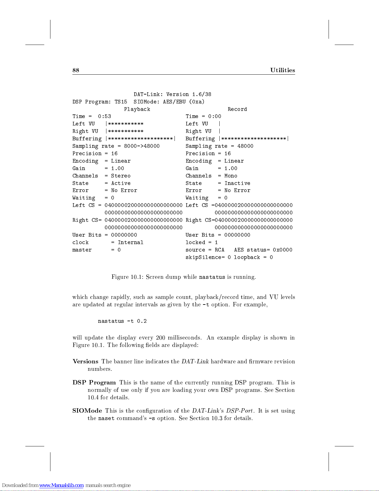
88 Utilities
DAT-Link: Version 1.6/38
DSP Program: TS15 SIOMode: AES/EBU (0xa)
Playback Record
Time = 0:53 Time = 0:00
Left VU |*********** Left VU |
Right VU |*********** Right VU |
Buffering |********************| Buffering |********************|
Sampling rate = 8000->48000 Sampling rate = 48000
Precision = 16 Precision = 16
Encoding = Linear Encoding = Linear
Gain = 1.00 Gain = 1.00
Channels = Stereo Channels = Mono
State = Active State = Inactive
Error = No Error Error = No Error
Waiting = 0 Waiting = 0
Left CS = 040000020000000000000000 Left CS =040000020000000000000000
000000000000000000000000 000000000000000000000000
Right CS= 040000020000000000000000 Right CS=040000020000000000000000
000000000000000000000000 000000000000000000000000
User Bits = 00000000 User Bits = 00000000
clock = Internal locked = 1
master = 0 source = RCA AES status= 0x0000
skipSilence= 0 loopback = 0
Figure 10.1: Screen dump while
whichchange rapidly, such as sample count, playback/record time, and VU levels
are up dated at regular intervals as given by the-toption. For example,
nastatus -t 0.2
will update the display every 200 milliseconds. An example display is shown in
Figure 10.1. The following elds are displayed:
Versions
DSP Program
SIOMode
The banner line indicates the
numbers.
This is the name of the currently running DSP program. This is
normally of use only if you are loading your own DSP programs. See Section
10.4 for details.
This is the conguration of the
the
naset
command's-soption. See Section 10.3 for details.
nastatus
DAT-Link
DAT-Link'sDSP-Port
hardware and rmware revision
is running.
. It is set using
Page 93
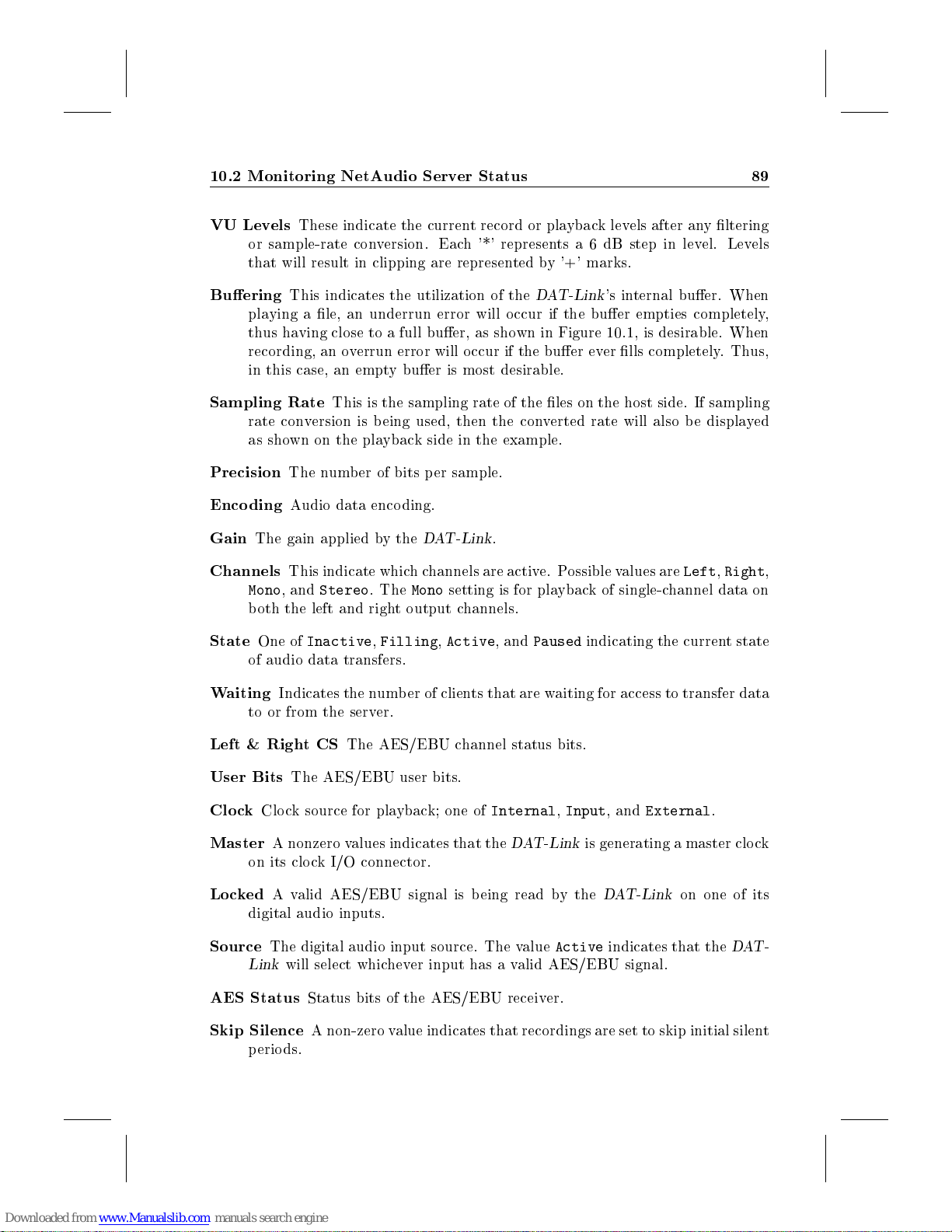
10.2 Monitoring NetAudio Server Status 89
VU Levels
or sample-rate conversion. Each '*' represents a 6 dB step in level. Levels
that will result in clipping are represented by '+' marks.
Buering
playing a le, an underrun error will occur if the buer empties completely,
thus having close to a full buer, as shown in Figure 10.1, is desirable. When
recording, an overrun error will o ccur if the buer ever lls completely. Thus,
in this case, an empty buer is most desirable.
Sampling Rate
rate conversion is being used, then the converted rate will also b e displayed
as shown on the playback side in the example.
Precision
Encoding
Gain
Channels
Mono
both the left and right output channels.
State
of audio data transfers.
These indicate the current record or playback levels after any ltering
This indicates the utilization of the
This is the sampling rate of the les on the host side. If sampling
The number of bits per sample.
Audio data enco ding.
The gain applied by the
This indicate whichchannels are active. Possible values are
, and
One of
Stereo
Inactive,Filling,Active
. The
DAT-Link
Mono
setting is for playback of single-channel data on
.
, and
DAT-Link
Paused
's internal buer. When
indicating the current state
Left,Right
,
Waiting
Left & RightCS
User Bits
Clock
Master
Locked
Source
AES Status
Skip Silence
Indicates the number of clients that are waiting for access to transfer data
to or from the server.
The AES/EBU user bits.
Clock source for playback; one of
A nonzero values indicates that the
on its clo ck I/O connector.
A valid AES/EBU signal is b eing read by the
digital audio inputs.
The digital audio input source. The value
Link
will select whichever input has a valid AES/EBU signal.
Status bits of the AES/EBU receiver.
A non-zero value indicates that recordings are set to skip initial silent
periods.
The AES/EBU channel status bits.
Internal,Input
DAT-Link
Active
, and
External
is generating a master clock
DAT-Link
indicates that the
.
on one of its
DAT-
Page 94
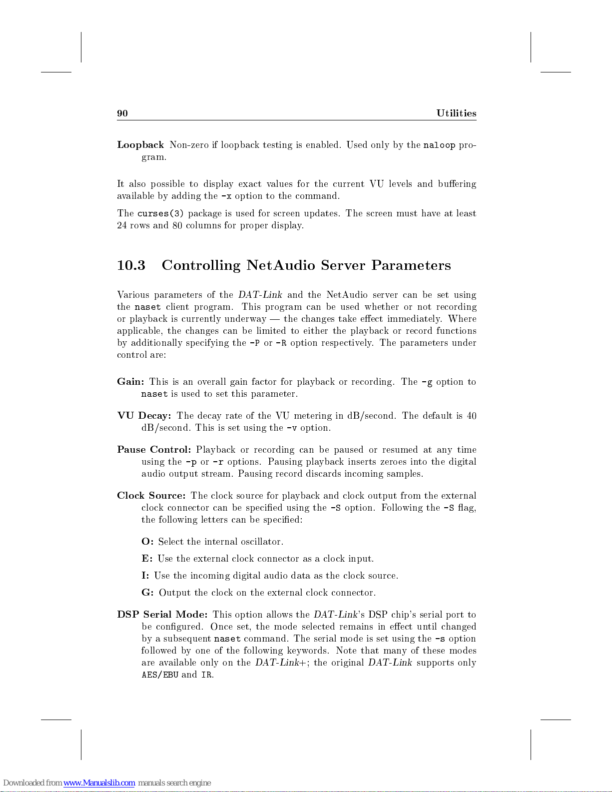
90 Utilities
Loopback
It also p ossible to display exact values for the current VU levels and buering
available by adding the-xoption to the command.
The
curses(3)
24 rows and 80 columns for proper display.
10.3 Controlling NetAudio Server Parameters
Various parameters of the
the
naset
or playback is currently underway | the changes take eect immediately. Where
applicable, the changes can be limited to either the playbackorrecord functions
by additionally sp ecifying the-Por-Roption respectively. The parameters under
control are:
Gain:
VU Decay:
Non-zero if lo opback testing is enabled. Used only by the
gram.
package is used for screen updates. The screen must have at least
DAT-Link
client program. This program can be used whether or not recording
This is an overall gain factor for playback or recording. The-goption to
naset
is used to set this parameter.
The decay rate of the VU metering in dB/second. The default is 40
dB/second. This is set using the-voption.
and the NetAudio server can be set using
naloop
pro-
Pause Control:
using the-por-roptions. Pausing playback inserts zeroes into the digital
audio output stream. Pausing record discards incoming samples.
Clock Source:
clock connector can b e sp ecied using the-Soption. Following the-Sag,
the following letters can b e specied:
O:
Select the internal oscillator.
E:
Use the external clock connector as a clock input.
I:
Use the incoming digital audio data as the clock source.
G:
Output the clo ck on the external clock connector.
DSP Serial Mode:
be congured. Once set, the mode selected remains in eect until changed
by a subsequent
followed by one of the following keywords. Note that manyofthese modes
are available only on the
AES/EBU
Playback or recording can be paused or resumed at any time
The clock source for playback and clo ck output from the external
andIR.
This option allows the
naset
command. The serial mode is set using the-soption
DAT-Link
DAT-Link
+; the original
's DSP chip's serial port to
DAT-Link
supports only
Page 95
10.3 Controlling NetAudio Server Parameters 91
AES/EBU:
the DSP32C's serial port is connected to the digital audio inputs and
outputs.
AES/EBU-Override:
the
nected via the external
for playback and recording from a single unit when multiple units are
connected together.
GP-Int:
and load lines should be generated by the DSP32C and are output on
the appropriate pins of the
GP-Ext:
and load lines should be generated externally and are inputs to the
Link
GPDelay-Int:
bit-time.
GPDelay-Ext:
one bit-time.
AES-Rx:
DSP32C, but the
input and output is locked to the digital audio input.
AES-Tx:
audio output. Clocking for both input and output is locked to the digital
audio output.
Pro8:
ProPort connected to the
for details on using the ProPort. In this particular mo de the ProPort
will be set for input and output at 8,000 samples per second.
Pro11:
Pro16:
Pro32:
Pro44:
Pro48:
Pro96:
Pro-Int:
clock (set by the-Soption ab ove) as the ProPort's sample-rate clock.
IR:
The
input with clocks generated by the DSP32C. The DSP32C's serial output
is unused.
This is the normal mode for the
This is the same as the previous mo de except that
DAT-Link
The DSP32C's serial port is connected to the
The DSP32C's serial p ort is connected to the
's DSP32C processor.
The digital audio input is used as the source of input data to the
Input is taken from the
This mode permits both input and output to be routed via an Ariel
ProPort at 11,000 samples per second.
ProPort at 16,000 samples per second.
ProPort at 32,000 samples per second.
ProPort at 44,100 samples per second.
ProPort at 48,000 samples per second.
ProPort at 96,000 samples per second.
This ProPort mo de uses the
DAT-Link
+, version 1.6 or later will not wait for other devices con-
Sync
connector before beginning. This is useful
DSP-Port
Similar to GP-Int except the incoming data is delayed by one
Similar to GP-Ext except the incoming data is delayed by
DSP-Port
's infrared receiver is connected to the DSP32C's serial
is used for output. Clocking for b oth the
DSP-Port
DAT-Link
DAT-Link
.
and output is sent to the digital
+'s
DSP-Port
DAT-Link
. With this setting,
DSP-Port
DSP-Port
. See Section 11.3.1
+'s digital audio output
. The clock
. The clock
DAT-
Page 96
92 Utilities
TxFSync:
the DSP32C's serial input with clocks generated by the DSP32C. This
mode can be used to measure the sampling frequency of output when
locked to an external clo ck.
TxFSync:
DSP32C's serial input with clocks generated by the DSP32C. This mode
can be used to measure the sampling frequency of a digital audio inputs.
The
naset
by sp ecifying the-coption. The manual page for
these and other options.
10.4 Downloading DSP32C Programs
The
naloaddsp
programs to the
compiled and linked using AT&T's DSP32C Development System to create a COFF
executable le. Section 11.2.1 describes the interface to AT&T's software. To
download an executable named
naloaddsp -c foo
This will force the NetAudio server to use
DAT-Link
cluding
use
. Note that this will aect subsequent use of the NetAudio software in-
naplay,narecord
naloaddsp
The digital audio transmitter's sample-rate clock is connected to
The digital audio receiver's sample-rate clock is connected to the
program can also be used to reset the parameters to the default state,
naset
program provides a facility for users to download their own DSP
DAT-Link
with no arguments.
's DSP32C processor. The DSP32C program must be
foo
, use:
foo
during all transfers to or from the
, and
rctrain
.To return
in Appendix G discusses
DAT-Link
to normal op eration,
The name of the currently loaded DSP program can also be checked using the
option to
10.5 Checking the DAT-Link's Filters
When the
pass digital ltering to eliminating aliasing during the conversion process. Also,
custom lter responses can be sp ecied for equalization, notch ltering, and other
special applications. If it is necessary to obtain the exact specications of the lter
being used by the
1. Perform the op eration for whichyou want to examine the lter. For exam-
naloaddsp
naloaddsp -q
DAT-Link
ple, to examine the lter used for recording with conversion to 8000 sam-
ples/second, run the command:
:
is used for sample-rate conversion, it must perform some low-
DAT-Link
, the following procedure can b e used:
-q
Page 97
10.6 Interactive Playback of Multiple Files 93
narecord -s 8000 -t 1 >/dev/null
The output of the command is not important, it just forces the NetAudio
server to load the appropriate lters.
2. Run the program
playback or record lter respectively. To continue the above example, type:
nagetfilter -R >filter.specs
The output from
The rst line contains the sampling rate of the discrete-time lter's impulse re-
sponse. The remaining lines are the values of the sampled impulse response. This
impulse resp onse completely characterizes the
as input to other analysis programs or custom software to derive the frequency re-
sponse of the system. An example script to do this conversion and plot the results
using
MATLAB
STALLROOT/etc/dl/plotresp.m
the
DAT-Link
above commands are executed is shown in Figure 10.2.
10.6 Interactive Playback of Multiple Files
The
xnaplay
Window System to display a control panel on the workstation screen with a number
of buttons labelled with lenames. Clicking on any lename causes the le to be
played. An example panel is shown in Figure 10.3.
The
xnaplay
example, the panel shown in Figure 10.3 was generated using the command:
programs were installed. The plot generated byMATLAB after the
provides a simple interface to playbackmultiple les. It uses the X
program is run with each lename to be displayed as arguments. For
nagetfilter
nagetfilter
is included with the
are ASCI I oating point numbers, one per line.
with either the-Por-Roption to acquire the
DAT-Link
, where
INSTALLROOT
DAT-Link
software. The script is called
's lters. It can be used
IN-
is the directory where
xnaplay mozart_orig mozart@64kbps beethoven speech_orig \
speech_LPC speech_CELP
When a button on the
using the named le as the argument. If it necessary to pass some ags to the
naplay
with the lename. The command
will put up a display with buttons lab elled
le1
ples/second. Note that the quotes are necessary in the ab ove command to group
the options with the appropriate le.
program, such as setting the sampling rate, they can be sp ecied along
xnaplay '-s 8000 file1' '-s 12000 file2'
would be at 8,000 samples/second while
xnaplay
panel is clicked, the
le1
and
le2
naplay
will be played at 12,000 sam-
program is executed
le2
, but the playback of
Page 98
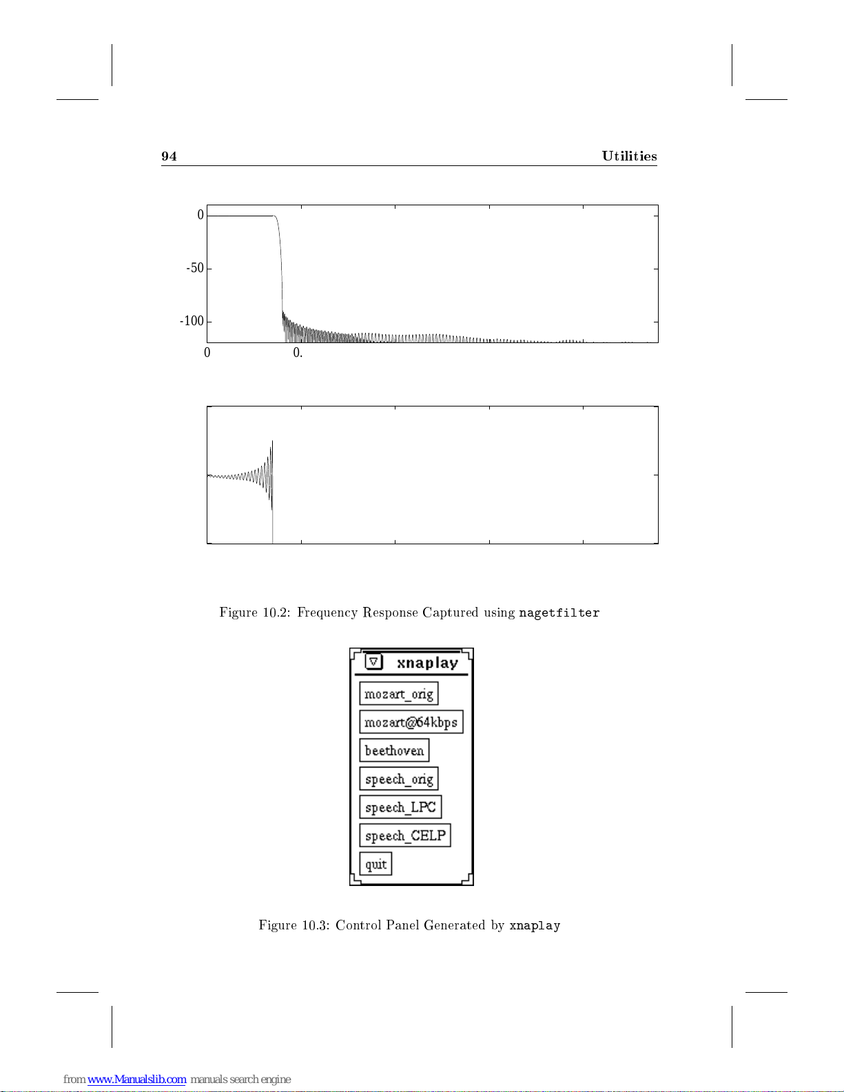
94 Utilities
Magnitude Response
0
-50
Atten (dB)
-100
0
0.5 1 1.5 2
Frequency (Hz)
-4
x10
5
0
Atten (dB)
-5
0 0.5 1 1.5 2
Frequency (Hz)
Figure 10.2: Frequency Response Captured using
nagetfilter
x10
x10
4
4
Figure 10.3: Control Panel Generated by
xnaplay
Page 99
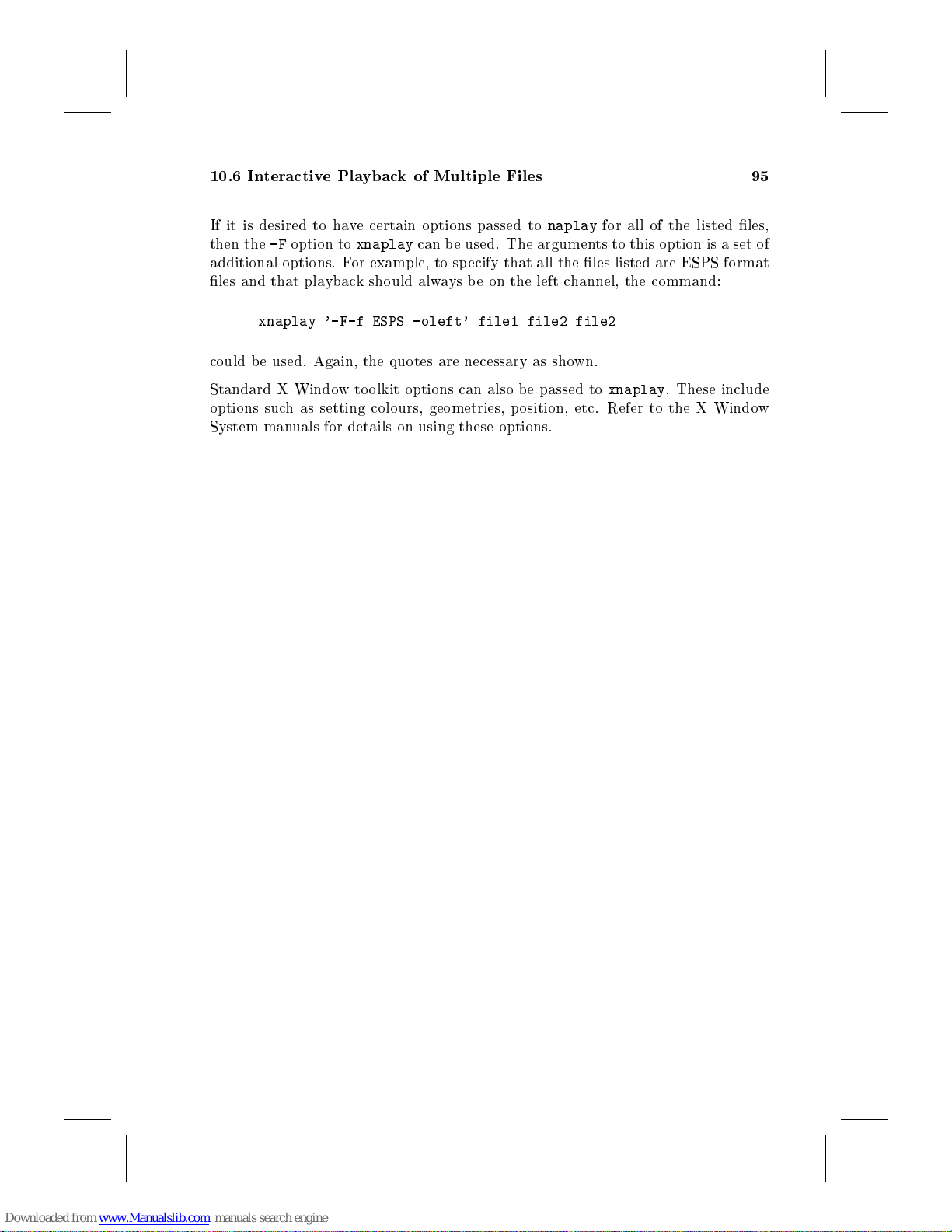
10.6 Interactive Playback of Multiple Files 95
If it is desired to have certain options passed to
then the-Foption to
additional options. For example, to sp ecify that all the les listed are ESPS format
les and that playback should always be on the left channel, the command:
xnaplay '-F-f ESPS -oleft' file1 file2 file2
could b e used. Again, the quotes are necessary as shown.
Standard X Window toolkit options can also be passed to
options such as setting colours, geometries, position, etc. Refer to the X Window
System manuals for details on using these options.
xnaplay
can be used. The arguments to this option is a set of
naplay
for all of the listed les,
xnaplay
. These include
Page 100

96 Utilities
 Loading...