

Town Food Service YF Installation Manual
Dragon Class Chinese Ranges by Town:
Models E, EF, Y, YF, M, MF
Express
THE WORLD'S FINEST CHINESE COOKING EQUIPMENT
OWNER’S MANUAL
SECTION I: INSTALLATION INSTRUCTIONS
For units shipped after June 2005 with new ue design
WARNING
IMPROPER INSTALLATION, ADJUSTMENT, ALTERATION, SERVICE
OR MAINTENANCE CAN CAUSE PROPERTY DAMAGE, INJURY OR
DEATH. READ THE INSTALLATION, OPERATING AND MAINTENANCE INSTRUCTIONS THOROUGHLY BEFORE INSTALLING OR
SERVICING THIS EQUIPMENT.
FOR YOUR SAFETY
DO NOT STORE OR USE GASOLINE
OR OTHER FLAMMABLE VAPORS AND
LIQUIDS IN THE VICINITY OF
THIS OR ANY OTHER APPLIANCE.
KEEP THIS BOOKLET HANDY FOR FUTURE REFERENCE
FOOD SERVICE EQUIPMENT CO., INC.
OBTAIN EMERGENCY PROCEDURES
FROM YOUR LOCAL GAS SUPPLIER IF
YOU SMELL GAS NEAR THIS EQUIPMENT.
THIS EMERGENCY INFORMATION MUST
BE PROMINENTLY DISPLAYED.
72 Beadel St., Brooklyn, NY 11222
(718) 388-5650 fax (718) 388-5860
customerservice@townfood.com
NOTE
1

CONGRATULATIONS
on your purchase of the new Dragon Class Express, York or MasteRRange. It will give you many years of
trouble free use if it is properly used and maintained. Feel free to call our Customer Service Department
if you have questions regarding operation or care of your Town range.
INSTALLATION INSTRUCTIONS
Express, YORK and MASTERRANGE
DRAGON SERIES CHINESE RANGES
Your Dragon class range has been carefully engineered and constructed with the best possible workmanship and materials to provide many years of satisfactory service. Proper installation is vital if appearance
and performance is to be achieved.
FOLLOW THESE INSTRUCTIONS CAREFULLY!
Express/YORK/MASTERRANGE INSTALLATION AREA MUST BE FREE AND CLEAR FROM COMBUSTIBLES
1. Position crate in approximate location that the unit will occupy. Uncrate range and locate sealed cartons on the range top containing the following accessories: One (1) set of adjustable legs; one (1) drip
pan for each chamber; and one (1) extension chimney for each opening in returnsplash if your unit is
equipped with a ue riser. "E" units do not have a ue riser and the chimney extension is not a part of
these ranges. Find the legs and set one leg by each range gusset into which it will be inserted. Raise
one end of the unit at a time; insert legs; and tighten set screws with 1/4" Allen wrench. If your range
has ue risers, slip the extension chimney over each riser.
2. Range is now ready for nal positioning. Carefully lift range into desired position to avoid damage to
adjustable legs. Clearances from combustible construction are 6" at rear and sides. Remove burner tie
wires and other packing materials. Check gas burners that may have shifted in transit and center them
by eye if required. Turn all gas valve lever handles to “OFF” (horizontal) position. Check air mixer
alignment to gas burner nipple and tighten set screws if necessary.
3. Clearances for noncombustible construction are the same as combustible clearances. This range is for
installation only on noncombustible oors.
INSTALLATION:
1. The gas supply line must be of adequate size to insure maximum efciency of the unit.
2. The installation must conform with the National Fuel Gas Code, ANSI Z223.1, Natural Gas Installation
Code, CAN/CGA-B149.1 or the Propane Installation Code, CAN/CGA-B149.2, as applicable, including:
a. The appliance and its individual shutoff valve must be disconnected from the gas supply piping
system during any pressure testing of that system at test pressures in excess of 1/2 psi (3.45 kPa).
b. The appliance must be isolated from the gas supply piping system by closing its individual manual
valve during any pressure testing of the gas supply piping system at test pressures equal or less than
1/2 psig (3.45 kPa).
2
FOOD SERVICE EQUIPMENT CO., INC. • 72 BEADEL ST • BKLYN • NY 11222

3. Local regulations governing gas appliance installations must be complied with.
4. Equipment should be under hood with adequate ventilation.
5. Minimum spacing of 6" to combustible construction is required along back and side walls. Clearances
for noncombustible construction are the same as combustible clearances. For use only on noncom-
bustible oors.
6. Materials such as wood, compressed paper and plant bers that will ignite and burn, Must Not Be
Exposed Near Range Especially at Rear. Local safety codes should be complied with in respect to re
hazard avoidance.
7. Use of the supplied pressure regulator is mandatory.
8. The front of the unit must be kept clear to avoid restriction of air supply for combustion.
9. The unit must be installed in an area or room with sufcient fresh air supply to ensure proper combus
tion.
10. There must be adequate clearance for air openings into the combustion chamber.
11. This equipment must be installed with adequate clearance for servicing and proper operation.
12. This unit should be operated only with drip trays in place.
13. If your unit is supplied with casters, the installation shall be made with a connector that complies with
the Standard for Connectors for Movable Gas Appliances, ANSI Z21.69 or Connectors for Moveable
Gas Appliances, CAN/CGA-6.16, and a Quick Disconnect device that complies with the Standard
for Quick-Disconnect Devices for Use with Gas Fuel ANSI Z21.41, or Quick Disconnect Devices for
Use with Gas Fuel, CAN1-6.9, and adequate means must be provided to limit the movement of the
appliance without depending on connector and the quick-disconnect device or its associated piping
to limit the appliance movement.
-
14. If your unit is provided with casters on legs, the legs with locking casters must be installed in front of
the unit. An approved restraining device must be secured to unit rear or side.
IMPORTANT
1. Before connecting gas and water supply, the range deck must be pitched so water will drain off range
top into the gutter, and into the internal or external slop sink.
2. Range deck pitch is adjusted by raising or lowering each leg as necessary at the adjustable foot. Raise
front legs or lower rear legs of the unit to provide pitch for water to drain into gutter at rear. Ranges
with external sinks: Observe that water drains out of gutter at open end. If water remains in gutter,
lower legs on discharge end, or raise legs at opposite end.
3. Connect the gas supply line to unit using the pressure regulator provided. A readily accessible ap-
proved type gas shutoff should be supplied by others. Water supply line on back of unit and sprinkler
should be connected with a shutoff valve in readily accessible location.
4. Check that all gas valves on the unit are turned “OFF” (lever handles in horizontal position) before
turning “ON” main gas line. Check for leaks using soapy water or other suitable leak detector. DO
NOT USE OPEN FLAME FOR TESTING. Check that swing faucets and sprinkler valve are in “OFF”
position (spout parallel to backsplash), open water valve and check for leaks.
5. UNITS WITHOUT SAFETY VALVES: LIGHTING AND SHUT DOWN INSTRUCTIONS
Be sure that all piping is gas tight and that all air is purged from lines. With Main Burner Valve in “OFF”
position (see g.2), using a screw driver turn pilot screw counter clockwise to “ON” (see g. 1) and light
(718) 388-5650 (800) 221-5032 except NY fax: (718) 388-5860 townfood.com
3
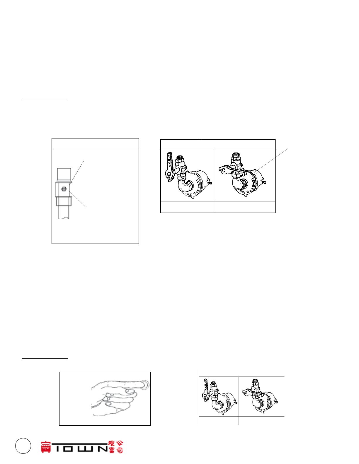
pilot located in the combustion chamber. Make sure the pilot stays lit.
All units are equipped with xed orices which cannot be adjusted for gas ow. Only ring burners have
adjustable air mixers to adjust the air/gas mixture.
Turn right hand burner valve to full “ON” position (see g.2) and adjust air shutter until proper blue ame is
burning on both inner rings. Repeat operation for left hand valve only if your range is equipped with three
ring burners.
SHUTDOWN: Turn burner valves to "OFF" position (see g.2) and turn the pilot screw clockwise (see g.
1) until it cannot be turned further. Repeat this step for each chamber.
OPERATING INSTRUCTIONS
1. INSTALLATION AREA MUST BE FREE AND CLEAR FROM COMBUSTIBLES. Local safety codes should
be complied with in respect to re avoidance.
PILOT VALVE
FIGURE 1
OFF position:
turn clockwise
until screw cannot be turned
further
ON position
MAIN BURNER VALVE
ON position OFF position
air shutter
(ring
burners
only)
FIGURE 2
turn counterclockwise
6. UNITS WITH SAFETY VALVES: LIGHTING AND SHUT DOWN INSTRUCTIONS.
Always follow these lighting and shutdown instructions when operating your unit. A ve minute com-
plete shutoff period is required before lighting or relighting pilot. See diagram below.
a) Check that all gas valves on the unit are turned “OFF” (lever handles in horizontal position) before turn-
ing “ON” main gas line. Check for leaks using soapy water or other suitable leak detector. DO NOT
USE OPEN FLAME FOR TESTING.
b) Main burner valve shall be in “OFF” position (gure 2). Place a burning match by the pilot burner in the
combustion chamber of the range. Depress safety control red button on (g.1 below) and light pilot.
c) The pilot should light. Continue to hold the button for one minute or until the pilot stays lit.
SHUT DOWN: For temporary Shut Down turn all burner valves to "OFF" position. For an extended period of time, turn all burner valves "OFF" and also turn off gas supply to the range.
MAIN BURNER VALVE
Put lit match
to pilot
burner, depress & hold
red button
ON position
gure 1
4
FOOD SERVICE EQUIPMENT CO., INC. • 72 BEADEL ST • BKLYN • NY 11222
OFF position
gure 2
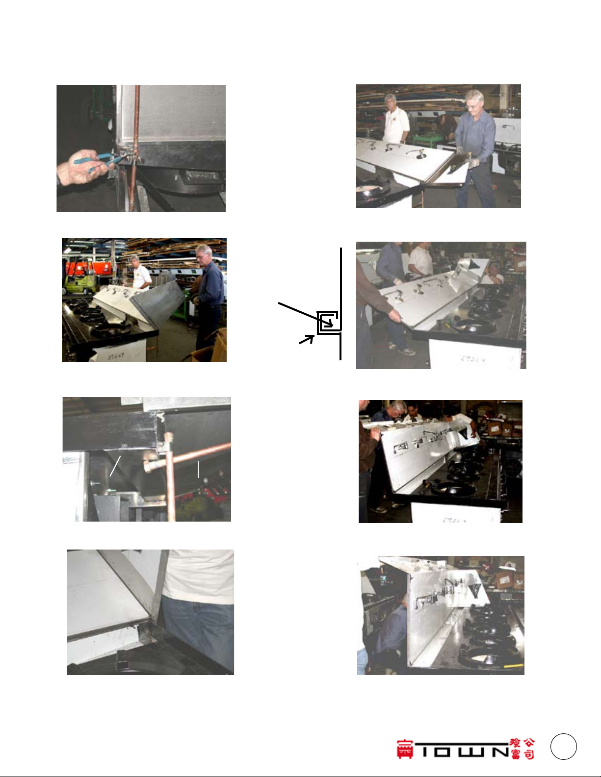
BACKSPLASH REMOVAL & REINSTALLATION
Some installations require the backsplash to be removed so the range can t through a 34" door. Town
ranges are manufactured with removable backsplashes. Follow these steps:
1. Loosen union at backsplash
backsplash "J"
gutter "J"
2. Remove sidesplash bolts and lower backsplash
gutter
faucet
manifold
5. Sidesplash may be removed. Range will
t through 34" opening.
6. Reinsert sidesplash and backsplash into gutter.
Insure backsplash "J" hooks into gutter "J".
3. Faucet manifold must beplaced below gutter
7. Raise backsplash, making sure it is locked into
the gutter "J".
4. Lower backsplash until sidesplash clears
gutter
(718) 388-5650 (800) 221-5032 except NY fax: (718) 388-5860 townfood.com
8. When raised, the gutter and backsplashed
should be aligned. Bolt side splashes to body.
5
 Loading...