

Town Food Service SR-18R Operators Manual
DO NOT DISCARD INSTRUCTIONS. THIS MANUAL MUST REMAIN WITH THE UNIT FOR FUTURE REFERENCE.
THIS EMERGENCY INFORMATION MUST BE PROMINENTLY DISPLAYED.
SR-24
STOCK POT STOVE OWNER’S MANUAL
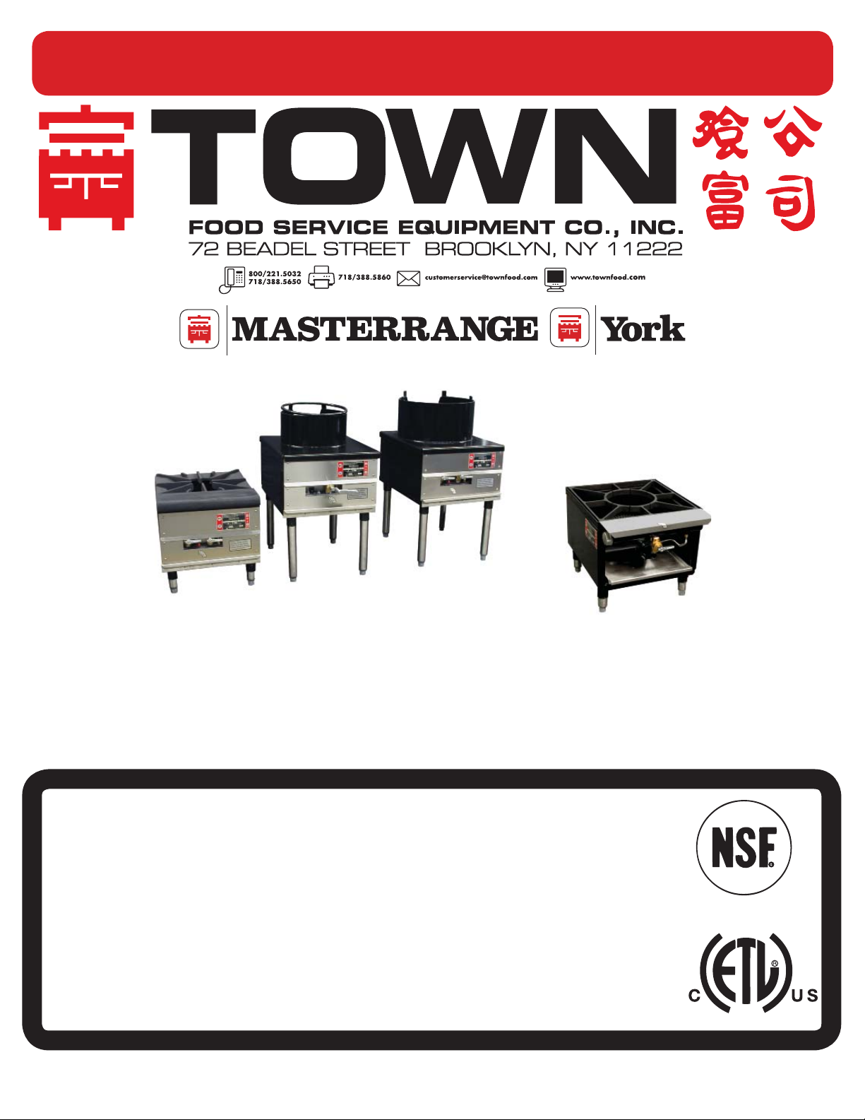
SR-18 stock pot range, grate top, front manifold|SR-18R stock pot range, grate top, rear manifold
SR-24 stock pot range, grate top
SR-24M
SR-24C
SR-18
|SR-24C 16” Cantonese wok top range|SR-24M 13” Mandarin wok top range
SECTION 1
INSTALLATION INSTRUCTIONS
FOR COMMERCIAL USE ONLY
Warning
Improper installation, adjustment, alteration, service or maintenance can cause property
damage, injury or death. Read the installation, operating and maintenance instructions
thoroughly before installing or servicing this equipment.
For your safety
Do not store or use gasoline or other fl ammable vapors and liquids in the vicinity of this or any
other appliance.
Note
Obtain emergency procedures from your local gas supplier if you smell gas near this equipment.
This emergency information must be prominently displayed
No part of this booklet or it ’s illustrations may be copied or reproduced without written authorization from Town Food Service Equipment Co., Inc.
© Town Food Service Equipment Company, Inc.
R
T
E
E
T
K
N
I
L
D
I
S
E
T
5/14

Congratulations on your purchase of a Town Food stock pot, or wok top stove.
STOCK POT AND WOK TOP RANGE INSTALLATION INSTRUCTIONS
______________________________________________________________________
It will give you many years of trouble free use if it is properly used and maintained. Please call
our customer service department at 718/388-5650 if you have questions regarding equipment
operation or care.
Your new Town Food stock pot, or wok top range has been carefully engineered and constructed with
the best possible workmanship and materials to provide many years of satisfactory service.
Proper installation is vital if best appearance and performance is to be achieved.
STOCK POT AND WOK TOP RANGE INSTALLATION INSTRUCTIONS
______________________________________________________________________
FOLLOW THESE INSTRUCTIONS CAREFULLY
For installation in noncombustible locations only. Minimum clearances from combustible
and noncombustible construction are 6" from sides and back. Installation area must be
free and clear from combustibles and should not obstruct the fl ow of combustion and
ventilation air.
1 Set the unit in the position it will occupy in the cooking area.
2 If the fl oor is not level, set height of each leg by adjusting the foot. Use a spirit level or shallow
pan of water set fl at on stove grate to check if level and make height adjustments.
3 Before connecting gas supply pipe, check clearance around stove by setting largest stock pot on
stove grate or wok on ring to be sure handles or edges are clear of other units.
SR-24G, SR-24C, SR-24M, SR-18R
4
Gas supply line should be connected at the lower rear of the unit. A readily accessible, approved
type shut off valve should be roughed into the gas supply line.
SR-18 ONLY
Gas supply line may be connected to either end of gas manifold and opposite end capped. A readily
accessible, approved type shut-off valve should be roughed into the gas supply line.
5 Gas supply line must be of adequate size to insure maximum effi ciency of the unit.
6 The front of the unit must be kept clear to avoid restriction of air supply for combustion.
7 The installation must conform with the local codes and with the National Fuel Gas Code
ANSI Z223.1.
a The appliance and it’s individual shut off valve must be disconnected from the gas
supply piping system during any pressure testing of that system at test pressures in excess
of ½ psig.
b The appliance must be isolated from the gas supply piping system by closing it’s individual
manual shut off valve during any pressure testing of the gas supply piping system at test
pressures equal to or less than ½ psig.
8 Local regulations governing gas appliance installations must be complied with.
9 Equipment should be under a hood with adequate ventilation.
10 Installation should be in noncombustible locations only. Minimum clearances from combustible
and noncombustible construction are 6” from sides and back.
11 Appliance area must be free and clear of combustibles. Materials such as wood, compressed
paper and plant fi bers that will ignite and burn must not be exposed near this unit.
Local safety codes should be complied with in respect to fi re avoidance.
12 The unit must be installed with adequate clearance for servicing and proper installation.
13 Provisions must be made for adequate air supply.
2
S
R-
2
S
2
S
2
C
S
8
LIGHTING AND SHUT DOWN INSTRUCTIONS
_____________________________________________________________________
4
R-
13 Use of the supplied pressure regulator is mandatory. For SR-18 with front manifold refer to
“
SR-18 front manifold units only”, below.
SR-18 FRONT MANIFOLD UNITS ONLY
Stock pot ranges with rear gas manifolds are designed for battery installation with interconnected
manifold and are not factory supplied with a gas pressure regulator. At time of installation the purchaser
of the equipment must obtain a regulator suitable for battery application. The regulator must be adjustable
for an outlet pressure appropriate for the manifold pressure on the appliance. This regulator must:
a Be listed by a nationally recognized testing agency.
b Have maximum regulation capacity for the total connected load.
c Be adjustable to the manifold pressure indicated on the rating plate.
d Unless the manifold pressure of all connected appliances is the same, a separate regulator
must be supplied for each unit(s) to indicate unit or units having differing manifold pressures.
4M
R-
4
R-1
14 Check that gas valve on unit is in OFF position (lever handle at horizontal position) before turning
shut off valve on.
15 Check for gas leaks using soapy water or some other suitable leak detector.
Do not use open fl ame for testing.
LIGHTING AND SHUT DOWN INSTRUCTIONS
_____________________________________________________________________
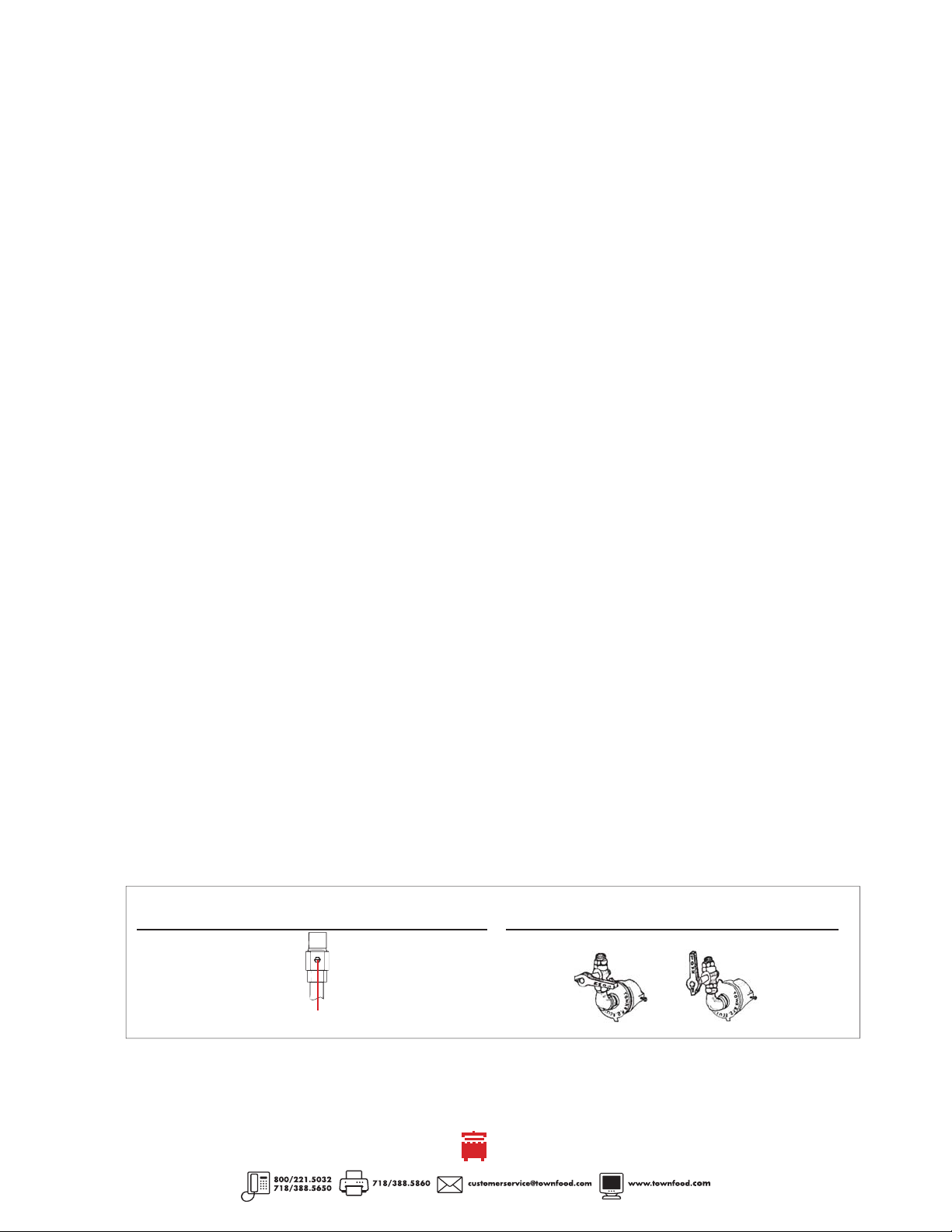
Be sure that all piping is gas tight and that all air is purged from lines. With main burner valve in OFF
position (see fi gure 2), using a screw driver turn pilot screw counter clockwise to ON (fi gure 1) and
light pilot located in the combustion chamber. Make sure the pilot stays lit.
All units are equipped with fi xed orifi ces which cannot be adjusted for gas fl ow. Only ring burners have
adjustable air mixers to adjust the air/gas mixture.
Turn right hand burner valve to full on position (fi gure 2) and adjust air shutter until proper blue fl ame is
burning on both inner rings. Repeat operation for left hand valve only if range is equipped with
3 ring burners.
SHUTDOWN
DAILY
Turn burner valves to OFF position (fi gure 2) and turn the pilot screw counter-clockwise (fi gure 1)
until it cannot be turned further.
LONG TERM
For an extended period of time, turn all burner valves to OFF position and turn off gas supply to
the range.
fi gure 1
pilot valve
ON POSITION
turn clockwise until
screw cannot be turned
PILOT SCREW
OFF POSITION
turn counter-clockwise
fi gure 2
main burner valve (AIR SHUTTER, RING BURNERS ONLY)
ON POSITION
3
OFF POSITION
 Loading...