

Town Food Service MBR-48C Installation Manual
DO NOT DISCARD INSTRUCTIONS. THIS MANUAL MUST REMAIN WITH THE UNIT FOR FUTURE REFERENCE.
THIS EMERGENCY INFORMATION MUST BE PROMINENTLY DISPLAYED.
MONGOLIAN BARBECUE RANGES
MBR-48
Warning
Improper installation, adjustment, alteration, service or maintenance can cause property
damage, injury or death. Read the installation, operating and maintenance instructions
thoroughly before installing or servicing this equipment.
For your safety
Do not store or use gasoline or other fl ammable vapors and liquids in the vicinity of this or any
other appliance.
Note
Obtain emergency procedures from your local gas supplier if you smell gas near this equipment.
This emergency information must be prominently displayed
MBR-48C | MBR-60 | MBR-60C | MBR-72 | MBR-72C | MBR-84 | MBR-84C
|
SECTION 1
INSTALLATION INSTRUCTIONS
FOR COMMERCIAL USE ONLY
R
T
E
E
T
K
N
I
L
D
I
S
E
T
No part of this booklet or it ’s illustrations may be copied or reproduced without written authorization from Town Food Service Equipment Co., Inc.
© Town Food Service Equipment Company, Inc.
2/13

8
8C
60
60C
C
84
8
C
Congratulations on your purchase of a Mongolian Barbecue. It will give you many years of trouble free use if it
_________________________________________________________________________________
is properly used and maintained. You can now produce delicious, juicy barbecue quickly and easily. Feel free to call
our customer service department at (718) 388-5650 if you have questions regarding equipment operation or care.
FOLLOW THESE INSTRUCTIONS CAREFULLY
4
Your new Mongolian Barbecue Range has been carefully engineered and constructed with the best possible
workmanship and materials to provide many years of service. Proper installation is vital for optimal appearance
and performance.
INSTALLATION INSTRUCTIONS FOR MONGOLIAN BBQ RANGE MODELS:
MBR-48, MBR-48-C, MBR-60, MBR-60-C, MBR-72, MBR-72-C, MBR-84, MBR-84-C
PLANNING AND SITE PREPARATION
_________________________________________________________________________________
PLANNING THE INSTALLATION OF YOUR MBR IS IMPORTANT
MBR-
UNCRATING AND PREPARING MBR UNITS FOR INSTALLATION
We recommend a licensed rigger be used to set up this equipment. It has been shipped in two crates:
• CRATE A MAIN COOKING UNIT
• CRATE B ROUND COOK TOP
MBR-
Installation area must be free and clear from combustibles.
The bottom of the main unit has a set of parallel rails designed to be engaged by a pallet jack or a forklift.
The main unit with the top mounted weighs approximately 1500-2100 pounds. We do not recommend moving
the unit after the top has been mounted. Use a lifting device rated in excess of that amount to lift the load.
OSHA standards for equipment handling must be adhered to. Be sure that the fork rails are properly mated
with the jack and/or the forks or serious damage and/or injury may result when the unit is lifted.
1 Uncrate the main unit and the top.
MBR-
2 Place the main unit in the position it will occupy. Be sure to locate your unit with the clearances away
from combustible construction as indicated on the nameplate of the unit. Remove packing materials.
Check gas burners that may have shifted in transit and resecure them if required. Turn all gas valve
lever handles to off position. Check to ensure that all burner pipe nipples are aligned and fully inserted into
air mixers. Tighten air mixer set screws if necessary.
3 Clearances for noncombustible construction are the same as combustible clearances. All MBRs are only
suitable for installation on noncombustible fl oors.
4 Level the body before the cook top is mounted. Leveling of the top is done using directions that follow after the
BR-4
cook top has been placed on the body and the gas connection has been made.
When the unit is in fi nal operating position confi rm that all of the top support lugs are the same height AFF.
Each bullet leg must touch the fl oor.
MBR-
BR-72
Body must be level in fi nal position before connecting gas.
BR-4
BR-72
2

BODY INSTALLATION
_________________________________________________________________________________
_________________________________________________________________________________
1 We recommend the use of a 2” gas line to feed the unit. Minimum line size is 1½”.
Large MBR units will not perform as designed if an insuffi ciently sized gas line is attached.
2 The installation must conform with the National Fuel Gas Code, ANSI Z223.1, Natural Gas Installation Code,
CAN/CGA-B149.1 or the Propane Installation Code, CAN/CGA-B149.2, as applicable, including:
a The appliance and it’s individual shutoff valve must be disconnected from the gas supply piping
system during any pressure testing of that system at test pressures in excess of ½ PSI (3.45 kPa).
This individual shut-off valve is a master valve that shuts off the gas to the entire unit and must be
installed to meet code requirements listed above.
b The appliance must be isolated from the gas supply piping system by closing its individual manual valve
during any pressure testing of the gas supply piping system at test pressures equal or less than ½ PSIG
(3.45 kPa).
3 Local regulations governing gas appliance installations must be complied with.
4 This equipment must be installed underneath a hood to ensure adequate ventilation.
5 MBR-48/84 installation is generally in the center of a cooking area with clear access on all sides.
6 Materials such as wood, compressed paper and plant fi bers that will ignite and burn, must not be
exposed near the range. Local safety codes should be complied with in respect to fi re hazard avoidance.
7 Use the Town supplied appliance gas pressure regulator with vent limiting device or an approved
ANSI/CGA equivalent. The regulator must be installed in a location where it remains cool and is
accessible for pressure adjustment (ANSI Z83.11-1996 sect. 1.15.5). Never mount regulator
inside grill body. (Town supplies an RV-61 1¼” NPT.)
a. If this unit is installed in a building with a 2 PSI gas system, a fi rst stage “pounds to inches” line
regulator must be installed upstream of the appliance regulator. This regulator is to be supplied by the
installing company/contractor.
8 The unit must be kept clear to avoid restriction of air supply for combustion.
9 The unit must be installed in an area or room with suffi cient fresh air supply to ensure proper combustion.
10 There must be adequate clearance for air openings into the combustion chamber.
11 This equipment must be installed with adequate clearance for servicing and proper operation.
12 This unit should be operated only with drip pan in place.
3

8
8C
60
60C
C
84
8
C
TOP INSTALLATION
_________________________________________________________________________________
_________________________________________________________________________________
_________________________________________________________________________________
1 There are leveling screws on the top of the main body. The height of the screws has been adjusted at the fac
tory to ensure proper combustion. Do not change the settings except in order to adjust the leveling of the top.
2 Never place any part of your body between the cook top and the main unit. Never place your hands underneath
the top or in the gap between cook top and the main unit.
3 If you have a model with a scrap chute, we recommend mounting the scrap chute after the top is in position.
4 After verifying that the adjusting screws are locked in place, lift the top into position over the main cooking
unit by using an ANSI approved sling (fabric or chain) that engages a minimum of 3 places on the outside
perimeter of the cook top. If your unit has a scrap chute, use a second ANSI sling to engage the central inner
hole of the cook top in three places thereby giving six points of support to the top as it is lifted into place.
5 Lower the top slowly so that the leveling screws are all located underneath the top. This alignment must be done-
MBR-
manually. Line up the top so that it is equal distance on all sides from the scrap shelf. It is recommended that
several persons assist during the set up operation. When the top is in position there will be a gap between the
top and the base of the unit. This is normal. It allows airfl ow for proper combustion.
6 Level the cook top. Use two carpenter levels; place them on the top at right angles to each other at opposite
ends of the top. Use the adjustment screws to level the top. When top is level move the levels 90˚ and level
again. Move levels as necessary until the entire top is level to the fl oor. The nominal height from the cooking
surface to the scrap ring is 8-9”.
4
MBR-
7 Remove the slings from the cook top.
MBR-
8 As a fi nal check, measure the height from the top of the cooking surface to the fl oor. The size should measure
37½” (+/- ½”).
9 All units: place the scrap cups into position.
10 Top must be properly seasoned (see page 11).
LIGHTING AND SHUT DOWN INSTRUCTIONS
_________________________________________________________________________________
Always use the following lighting and shutdown instructions below when operating your MBR.
A 5 minute complete shut off period is required before lighting or relighting an MBR. See diagrams on page 5.
BR-4
1 Before allowing gas to fl ow to the MBR, ensure all MBR gas valves are off by turning each handle clockwise.
Check for leaks using soapy water or another suitable leak detector.
2 Use a gas match to light the burner pilots. See fi gures 1-4, on page 5. Also refer to pages 12-14 for additional
safety pilot valve guidelines from the manufacturer, Robertshaw.
MBR-
BR-72
Do not use an open fl ame for testing.
BR-4
BR-72
4
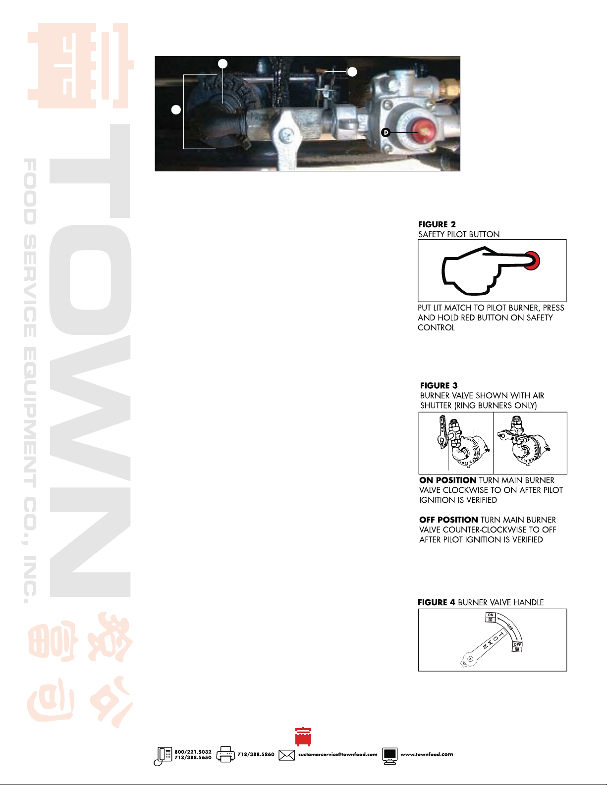
FIGURE 1
AIR SHUTTER, PILOT, SAFETY PILOT ASSEMBLY
POSITION LIGHTER ROD WITH LIT MATCH OVER PILOT LIGHT (C)
B
A
A AIR SHUTTER B AIR SHUTTER LOCKING NUT
C PILOT LIGHT (POSITION LIGHTER ROD WITH LIT MATCH) D SAFETY PILOT IGNITION BUTTON
3
Burner valves should be in off position (fi gure 3). An ignition port is provided for
C
each pilot burner. Use a fl ashlight to locate each prior to inserting a lighting device. Until one is familiar with lighting the unit, it is recommended one person light
the pilots and the second to locate and hold the red button on each safety control.
4
Starting at scrap bin access door, insert the ignited lighter through the ignition port
and light the pilot burner as you push and hold the red button on the safety control
(fi gure 2).
On initial startup, allow 5 to 15 minutes for air trapped in the gas lines to bleed
while holding the safety control ignition button. A qualifi ed gas service technician
can bleed the line from the pressure test port. It is located on the manifold to the
right of the front access door.
5
The pilot should light. Continue to hold the button for one minute as in
fi gure 2 or until the pilot stays lit. Repeat the above step until all pilots are lit.
6
With all pilots lit, turn each main burner valve counter clockwise to on position
(fi gure 3). Be sure all burners are visable through the ports are lit with a clear, blue
fl ame about 2” long. Each burner has an adjustable air mixer that has been preset
at the factory but may need to be adjusted depending on altitude and gas composition.
To adjust air/gas mixture, loosen air shutter locking nut. Turn burner valve to full on
position as in fi gure 3. Adjust air shutter until proper blue fl ame is burning on both
rings. Resecure locking nut on air shutter after making adjustments and turn off the
burner. All units are equipped with fi xed orifi ces which cannot be adjusted for gas
fl ow.
7
When unit is not in use, turn main burner valves clockwise to off position
(fi gure 3).
ON
BURNER
VALVE
AIR
SHUTTER
OFF
8
In the event of power failure, blackout or loss of gas do not attempt to
operate the unit.
9
In the event a complete shutdown is required the main service valve must be closed
in the off position. The service should be performed only by a qualifi ed gas service
mechanic.
5
ON TURN COUNTER CLOCKWISE
OFF TURN CLOCKWISE
 Loading...