

Town & Country Fireplaces TCWS.54STOK Installation And Operating Instructions Manual

INSTALLER: Leave this manual with the appliance.
CONSUMER: Retain this manual for future reference.
WARNING: If the information in these
instructions is not followed exactly, a re or
explosion may result causing property damage,
personal injury or death.
FOR YOUR SAFETY
Installation and service must be performed
by a quali ed installer, service agency or the
gas supplier.
WHAT TO DO IF YOU SMELL GAS
• Do not try to light any appliance.
• Do not touch any electrical switch
• Do not use any phone in your building.
• Immediately call your gas supplier from
a neighbour’s phone. Follow the gas
supplier’s instructions.
• If you cannot reach your gas supplier call
the re department.
SERIAL #
TCWS.54STOK
indoor/outdoor Fireplace
installation and operating
instructions.
Do not store or use gasoline or other ammable
vapors and liquids in the vicinity of this or any
other appliance.
This appliance may be installed in an aftermarket
permanently located, manufactured home (USA only)
or mobile home, where not prohibited by local codes.
This appliance is only for use with the type of gas
indicated on the rating plate. This appliance is
not convertible for use with other gases, unless a
certi ed kit is used.
This appliance is suitable for installation in a
bedroom or bed sitting room.
MODEL: TCWS.54STOK
SERIES D
POWER VENTED FIREPLACE
SEE THRU FIREPLACE
061115-56 TCWS54.STOK 5055.545-A
Table of Contents
DANGER
Caution ...................................................................3
Safety .....................................................................3
R-Value Statement..................................................3
Important Note for the Commonwealth
of Massachusetts: ................................................... 4
Fireplace Dimensions ............................................. 5
Minimum Clearances to Combustible Material .......6
Installation Requirements ....................................... 7
Manufactured (Mobile) Home ................................. 7
Window Frame Removal .........................................7
Standoffs.................................................................8
Locating The Fireplace ...........................................8
Framing and Finishing ............................................9
Building envelope sealing procedure .................... 10
Building materials - outer trim prole view ............ 11
Adjustable Lintel ...................................................14
Electrical ............................................................... 16
Wall Switch and Remote Control .......................... 17
Selecting Natural Vent & Power Vent Modes ........ 17
Home Automation ................................................. 18
Gas Supply ........................................................... 19
Venting ..................................................................20
Venting Congurations..........................................21
Venting Length ......................................................21
Minimum Vent Length Chart .................................22
Vent Terminal Minimum Clearances .....................22
Venting Components ............................................23
Vent Pipe Sealant ................................................. 24
Optional Tranquility Burner ...................................25
Propane Conversion .............................................31
Optional Twilight Diamond Burner ........................33
Gas Pressure Check .............................................37
Burner Flame Adjustment .....................................38
Firebox Panels Installation ....................................39
Finishing Touch Trim Kit Instructions ..................... 40
Lighting Instructions .............................................41
First Fire ................................................................42
Special Operator Note .......................................... 42
Remote Control Operation .................................... 42
Maintenance ......................................................... 48
Replacement parts - TCWS.54STOK ................... 49
Replacement Parts - TCWS.54DST .....................50
Replacement Parts - Tranquility Burner ................ 51
Replacement Parts - Twilight Diamond Burner ..... 52
Replacement Parts - Valve Control System ......... 53
Wiring Diagram ..................................................... 54
Rating Label TCWS54STOK ................................55
!
HOT GLASS WILL CAUSE
A barrier designed to reduce the risk of burns from the
hot viewing glass is provided with the appliance and
shall be installed for the protection of children and
other at-risk individuals.
5055.545-A
DO NOT TOUCH GLASS UNTIL
NEVER ALLOW CHILDREN TO
BURNS.
COOLED.
TOUCH GLASS.
2
We recommend that our gas hearth
products be installed and serviced
by professionals who are certied
in the United States by the National
Fireplace Institute
Specialists
®
(NFI) as NFI Gas
TCWS54STOK_061115-56

R - Value Statement
It has been determined that the Town and Country model TCWS.54STOK indoor/outdoor Fireplace has an R value of 5.8.
This determination has been arrived at by the calculation of the typical R value of two layers of 5mm Ceramic glass, combined with
17 inches of ventilated air gap. The one layer of 5mm tempered glass has been ignored in the calculation due to it being open to the
exterior air environment on both sides. Real world results may vary due to environmental factors.
Caution
FOR YOUR SAFETY - Do not install or operate your Town & Country replace without rst reading and understanding this manual.
Any installation or operational deviation from the following instructions voids the Town & Country Fireplaces
hazardous.
This appliance and its individual shut off valve must be disconnected from gas supply piping system during any pressure testing of that
system at test pressures in excess of 1/2 psig (3.5 kPa).
This appliance must be isolated from the gas supply piping system by closing its individual manual shut off valve during any pressure
testing of the gas supply piping system at test pressures equal to or less than 1/2 psig (3.5 kPa).
Note: When lit for the rst time, the appliance will emit a slight odour for a couple of hours. This is due to the curing of paints, sealants
and lubricants used in the manufacturing process. This condition is temporary. Open doors and windows to ventilate area. Smoke and
fumes caused by the curing process may cause discomfort to some individuals.
Do not use the replace if any part has been under water. Immediately call a qualied service technician to inspect the replace and to
replace any part of the control system and any gas control which has been under water.
TM
Warranty and may prove
Safety
Due to high temperatures, this gas appliance should be located out of traffic and away from furniture and draperies.
Children and adults should be alerted to the hazards of high surface temperatures and should stay away to avoid burns or clothing
ignition.
Young children should be carefully supervised when they are in the same room as the appliance. Toddlers, young children, and others
may be susceptible to accidental contact burns. A physical barrier is recommended if there are at-risk individuals in the house. To restrict
access to a replace or stove, install an adjustable safety gate to keep toddlers, young children, and other at-risk individuals out of the
room and away from hot surfaces.
Clothing or other ammable material should not be placed on or near the appliance.
Any grill, panel or door removed for servicing the unit must be replaced prior to operating. Failure to do so may create a hazardous
condition.
Installation and repair should be done by a qualied service person. The appliance should be inspected before use and at least
annually by a professional service person. More frequent cleaning may be required due to excessive lint from carpeting, bedding
material, etc. It is imperative that control compartments, burners and circulating air passageways of the appliance be kept clean.
It is our policy that no responsibility is assumed by the Company or by any of its employees or representatives for any damages caused
by an inoperable, inadequate, or unsafe condition which is the result, either directly or indirectly, of any improper operation or
installation procedures.
This appliance must not be connected to a chimney ue serving a separate solid fuel burning appliance.
TCWS54STOK_061115-56
5055.545-A
3

Important Note for the Commonwealth of Massachusetts:
From Massachusetts Rules and Regulations 248 CMR 5.08:
(a) For all side wall horizontally vented gas fuelled equipment installed in every dwelling, building or structure used in whole or in part for residential
purposes, including those owned or operated by the Commonwealth and where the side wall exhaust vent termination is less than seven (7) feet above
nished grade in the area of the venting, including but not limited to decks and porches, the following requirements shall be satised.
1. INSTALLATION OF CARBON MONOXIDE DETECTORS. At the time of installation of the side wall horizontal vented gas fuelled equipment, the
installing plumber or gas tter shall observe that a hard wired carbon monoxide detector with an alarm and battery back-up is installed on the oor level
where the gas equipment is to be installed, in addition, the installing plumber or gas tter shall observe that a battery operated or hard-wired carbon
monoxide detector with an alarm is installed on each additional level of the dwelling, building or structure served by the side wall horizontal vented gas
fuelled equipment. It shall be the responsibility of the property owner to secure the services of qualied licensed professionals for the installation of
hard-wired carbon monoxide detectors.
a. In the event that the side wall horizontally vented gas fuelled equipment is installed in a crawl space or an attic, the hard-wired carbon monoxide
detector with alarm and battery back-up may be installed on the next adjacent oor level.
b. In the event that the requirements of this subdivision cannot be met at the time of completion of installation, the owner shall have a period of thirty
(30) days to comply with the above requirements; provided, however, that during said thirty (30) day period, a battery operated carbon monoxide detector
with an alarm shall be installed.
2. APPROVED CARBON MONOXIDE DETECTORS. Each carbon monoxide detector as required in accordance with the above provisions shall
comply with NFPA 720 and be ANSI/UL 2034 listed as IAS certied.
3. SIGNAGE. A metal or plastic identication plate shall be permanently mounted to the exterior of the building at a minimum height of eight (8) feet
above grade directly in line with the exhaust vent terminal for the horizontally vented gas fuelled heating appliance or equipment. The sign shall read, in
print size no less than one-half (1/2) inch in size, “GAS VENT DIRECTLY BELOW. KEEP CLEAR OF ALL OBSTRUCTIONS”.
4. INSPECTION. The state or local gas inspector of the side wall horizontally vented gas fuelled equipment shall not approve the installation unless,
upon inspection, the inspector observes carbon monoxide detectors and signage installed in accordance with the provisions of 248 CMR 5.089(2)(a) 1
through 4.
(b) EXEMPTIONS. The following equipment is exempt from 248 CMR 5.089(2)(a) 1 through 4.
1. The equipment listed in Chapter 10 entitled “Equipment Not Required To Be Vented” in the most current edition of NFPA 54 as adopted by the
Board; and
2. Product Approved side wall horizontal vented gas fuelled equipment installed in a room or structure separate from the dwelling, building or structure
used in whole or in part for residential purposes.
(c) MANUFACTURER REQUIREMENTS – GAS EQUIPMENT VENTING SYSTEM PROVIDED. When the manufacturer of Product Approved side wall
horizontally vented gas equipment provides a venting system design or venting system components with the equipment, the instructions provided by the
manufacturer for installation of the equipment and the venting system shall include:
1. Detailed instructions for the installation of the venting system design or the venting system components; and
2. A complete parts list for the venting system design or venting system.
(d) MANUFACTURER REQUIREMENTS – GAS EQUIPMENT VENTING SYSTEM NOT PROVIDED. When the manufacturer of a Product Approved
side wall horizontally vented gas fuelled equipment does not provide the parts for venting the fuel gases, but identies “special venting systems”, the
following requirements shall be satised by the manufacturer.
1. The referenced “special venting system” instructions shall be included with the appliance or equipment installation instructions; and
2. The “special venting systems” shall be Product Approved by the Board, and the instructions for that system shall include a parts list and detailed
installation instructions.
(e)) A copy of all installation instructions for all Product Approved side wall horizontally vented gas fuelled equipment, all venting instructions, all parts
lists for venting instructions, and/or all venting design instructions shall remain with the appliance or equipment at the completion of the installation.
5055.545-A
TCWS54STOK_061115-56
4
3 3/16"
1/2"
(see page 13)
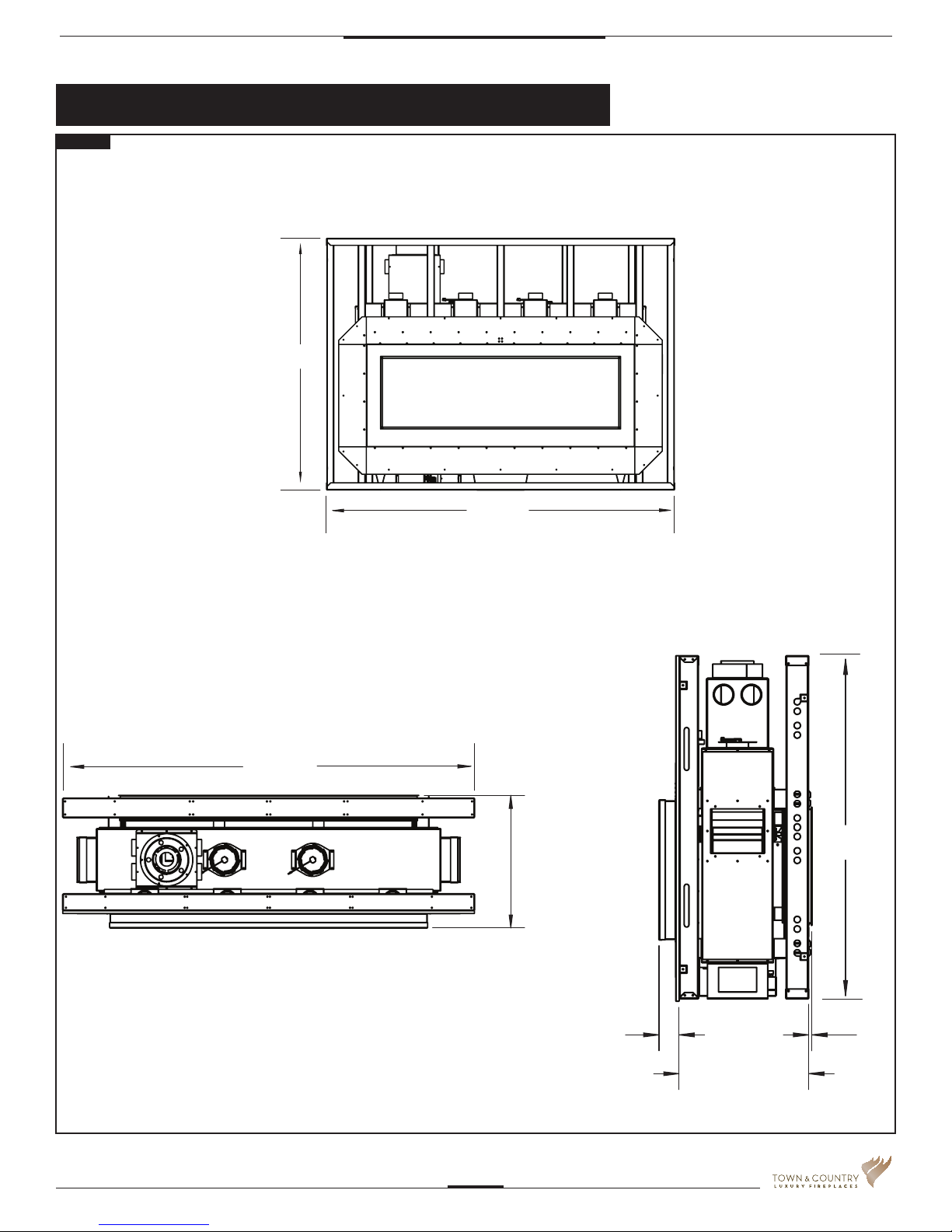
Fireplace Dimensions
Fig. #1
74 3/4"
74 3/4"
Top down view
Front view
variable
adjustment
54 1/16"
TCWS54STOK_061115-56
Prole view
5055.545-A
5
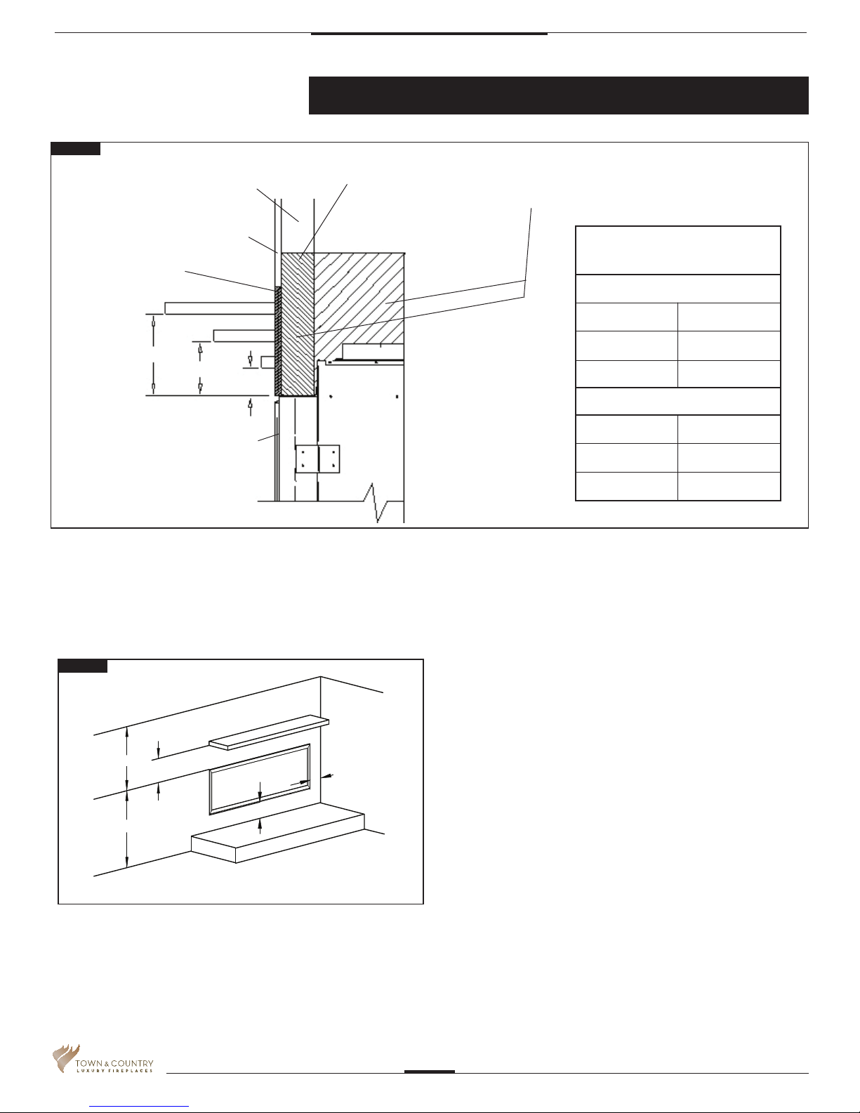
Minimum Clearances to Combustible Material
Fig. #2
COMBUSTIBLE FRAMING AND
FINISH WALL ABOVE STANDOFFS
MAY USE COMBUSTIBLE
FACING MATERIAL IN THIS AREA
NON-COMBUSTIBLE
FINISH MATERIAL
SEE FIG #11& 12
A
B
TOP OF LINTEL BAR
FIREPLACE FRONT
STEEL FRAMING
NON-COMBUSTIBLE ZONE.
DO NOT INSTALL ANY COMBUSTIBLE MATERIAL, ELECTRICAL WIRING OR GAS PLUMBING IN
THIS AREA.
MANTEL CLEARANCE
CHART
D
E
F
C
* MANTEL CLEARANCE
A 9”
B 6”
C 3”
** MANTEL DEPTH
D 12”
E 6 3/4”
F 1 1/2”
Fig. #3
CEILING
24"
*
6”
29 3/4"
COMBUSTIBLE HEARTH
COMBUSTIBLE FLOOR
5055.545-A
UNIT MAY BE RECESSED UP TO 6” WITH
NONCOMBUSTIBLE MASONRY TYPE MATERIAL
ADJACENT WALL
OR MANTEL SUPPORT
4“
6
Minimum Clearances:
Side standoffs ....................................................... 0 in. (0 mm)
Back standoffs ...................................................... 0 in. (0 mm)
Top standoffs ........................................................0 in. (0 mm)
Bottom of appliance .............................................. 0 in. (0 mm)
Adjacent side wall ................................................. 4 in. (102 mm)
Ceiling to appliance ............................................24 in. (610 mm)
*Mantel to appliance ................... ..........See Figure #2
**Maximum Mantel extension ..... ..........See Figure #2
Mantel support ...................................................... 4 in. (102 mm)
Vent pipe .......................................................1 3/4" in. (45 mm)
TCWS54STOK_061115-56
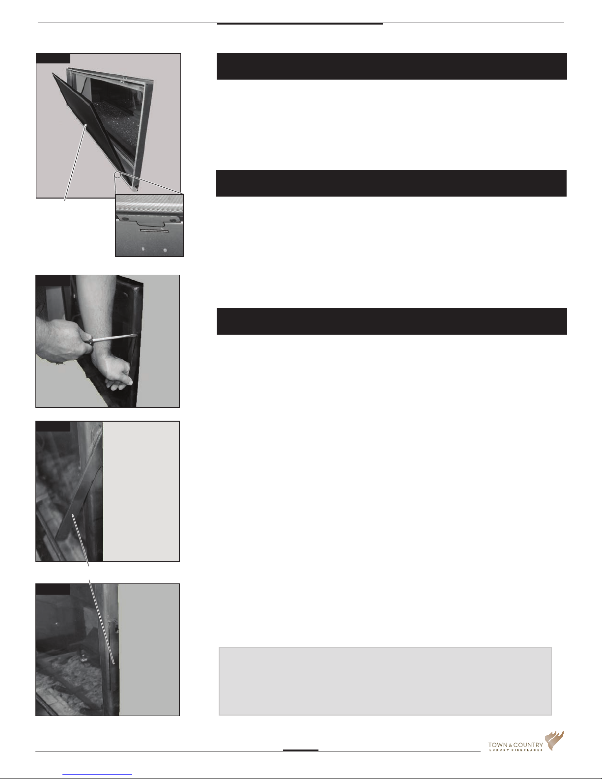
Fig. #4
Installation Requirements
The Town & Country Fireplace installation and venting must conform to the local codes
or, in the absence of local codes, current CSA B149.1 installation code (in Canada) or
the current National Fuel Gas Code, ANSI Z223.1/NFPA 54 (in the USA). Only qualied
(licensed or trained) personnel should install this product.
In the state of Massachusetts, only a licensed Plumber and Gas Fitter may install
this product.
Manufactured (Mobile) Home
SAFETY
BARRIER
SCREEN
Fig. #5
Fig. #6
In some jurisdictions, the Town & Country Fireplace may be installed in Manufactured Homes
after the "rst sale". Consult local codes for approval. The replace must be fastened
in place.
Install in accordance with the current standard Mobile Homes, CAN/CSA Z240 MH (in
CANADA), and the Manufacturer's Home Construction and Safety Standard, Title 24
CFR, Part 3280 or the current Standard for Fire Safety Criteria for Manufactured Home
Installations, Sites and Communities ANSI/NFPA 501A (in the USA).
Window Frame Removal
Warning: Turn off the replace, and allow ample time for the unit to cool before
proceeding.
Caution: The ceramic glass is very fragile, and should be handled with care.
The window frame is held in place by two spring-loaded latches that are operated by a
one-piece latch handle.
1. Remove Safety Barrier Screen (Fig. #4).
2. Remove the TC Finishing Touch Trim Kit from the window frame. (If installed)
3. Using a screwdriver (Fig #5) or other similar object, push against the notch in the top
of the latch and grab the bottom of the latch handle as it protrudes (Fig #6). Lift handle
until latch hook disengages. Repeat for other side while holding glass so it does not tip
out.
LATCH HANDLE
Fig. #7
TCWS54STOK_061115-56
4. Tilt the top of the window frame out to clear the top edge of the unit. Grasp the sides of
the frame and lift up and out to disengage from its bottom track.
5. Place the window frame in a safe place to avoid damage.
6. Re-assemble in reverse order. Latch handle should snap into place and be ush with
window frame when engaged correctly.
7. Reinstall Trim Kit if required.
8. Reinstall safety barrier screen.
TIP:
To ensure glass is properly latched, grasp the top left and
right sides of the glass frame, under moderate pressure it
should pull forward and return to original position evenly on
both sides.
5055.545-A
7
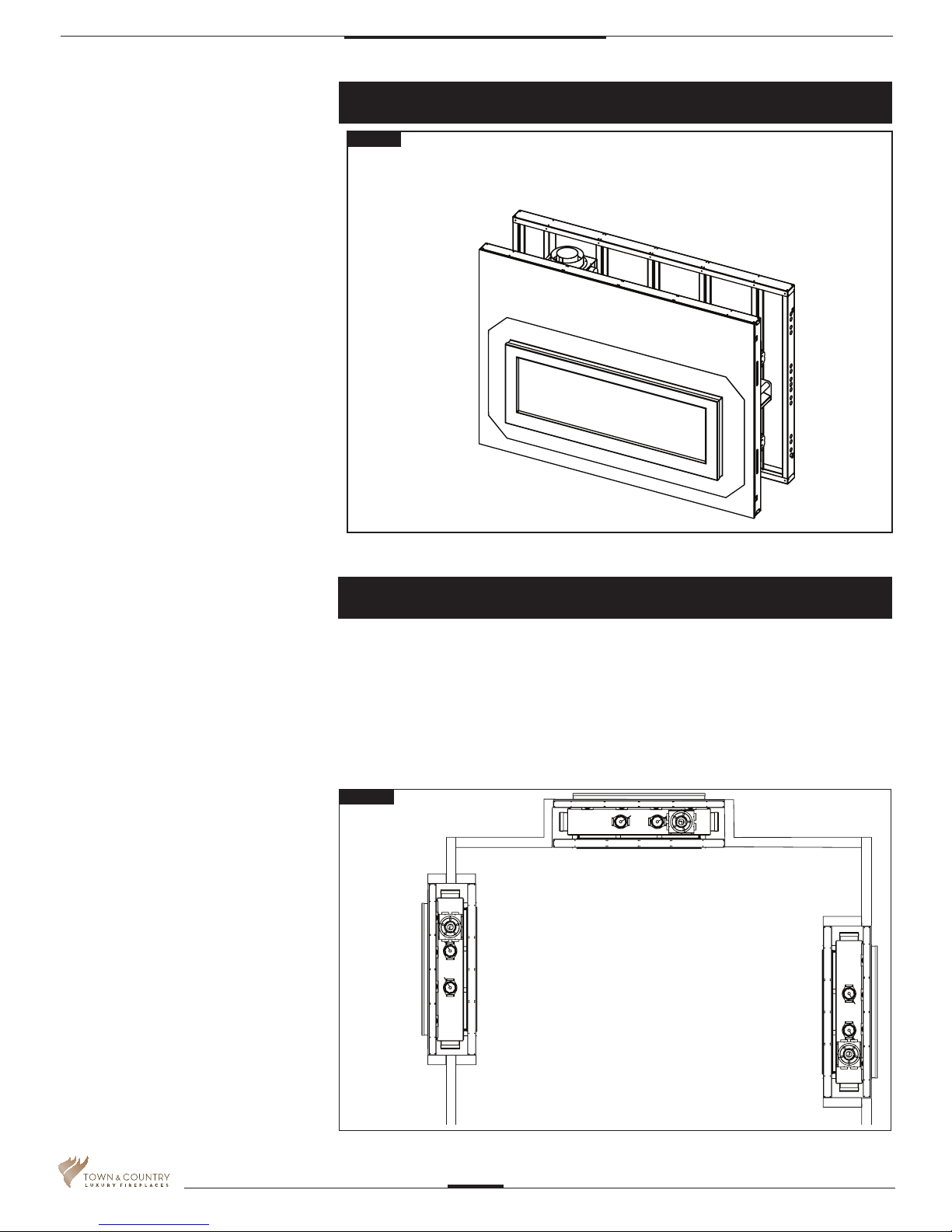
Standoffs
Fig. #8
The framing kits, once assembled
and attached, are used as the top
and side standoffs
Locating The Fireplace
In planning the installation for the replace, it is necessary to determine where the unit is to
be installed, location of vent system and where gas supply piping may be plumbed. Various
types of installations are possible, such as, a peninsula wall, an island, and between two
interior walls (Fig. #9). Due to high temperatures, do not locate this replace in areas of high
traffic or near furniture or draperies.
The minimum clearances from the replace to combustible surfaces must be adhered
to and are shown in Fig. #2 and Fig. #3.
Fig. #9
EXAMPLES OF COMMON
LOCATIONS SEE FIG #13 FOR
DIMENSIONS
5055.545-A
TCWS54STOK_061115-56
8
TCWS54 D-SERIES
Framing and Finishing
Note: The replace should be in place
and venting installed before framing in
or building an enclosure around the unit.
When the appliance is installed directly on
carpeting, tile or other combustible
material, other than wood ooring, the
appliance shall be installed on a metal or
wood panel extending the full width and
depth of the appliance.
The Town & Country replace must be
framed in as described below or totally
enclosed with non-combustible material,
such as facing brick.
Determine the total thickness of facing
material to be used. A thickness of 3/4" will
allow the nishing surface to be ush with
the front of the unit. If preferred, additional
masonry type non-combustible material
can be installed above and to the sides up
to 6 inches forward of the appliance.
*The nishing material must not interfere with glass frame access.*
A Steel Stud Framing Kit is supplied with
the replace and must be used unless the
replace is totally enclosed with
non-combustible material. The framing kit
comes fully assembled and the outdoor
section of the replace come fully insulated.
The sides and top of the replace are
framed in up to the steel studs using
conventional lumber. Consult local building
codes for specic requirements.
Due to high temperatures, non-combustible
backer board, such as cement board or its
equivalent, must be used to sheet in the front
of the replace, extending 12” above and 5
9/16” to the side of the framing edge bars.
(Fig #14) Standard sheet rock (dry wall) may
be used beyond this.
If the backer board is not to be nished with
other non-combustible material such as tiles, it
is recommended that top sections of the board
be a single sheet of calcium silicate board
or its equivalent. Taped and mudded joints
may crack due to the elevated temperatures.
Chase Insulation: When installing this
replace against a non-insulated exterior wall
or chase, it is recommended that the outer
walls be insulated to same degree as other
exterior walls. Do not place replace directly
against the insulation. Cover the insulation
and plastic vapour barrier with a solid surface,
such as dry wall (sheet rock). Consult local
codes. Do not insulate or use plastic vapour
barrier within the framing kit.
CAUTION: SEE FIGURE #14a BEFORE
PROCEEDING.
NOTE:
The chase must be properly
sealed at the ceiling level or
between oors in a multilevel
installation.
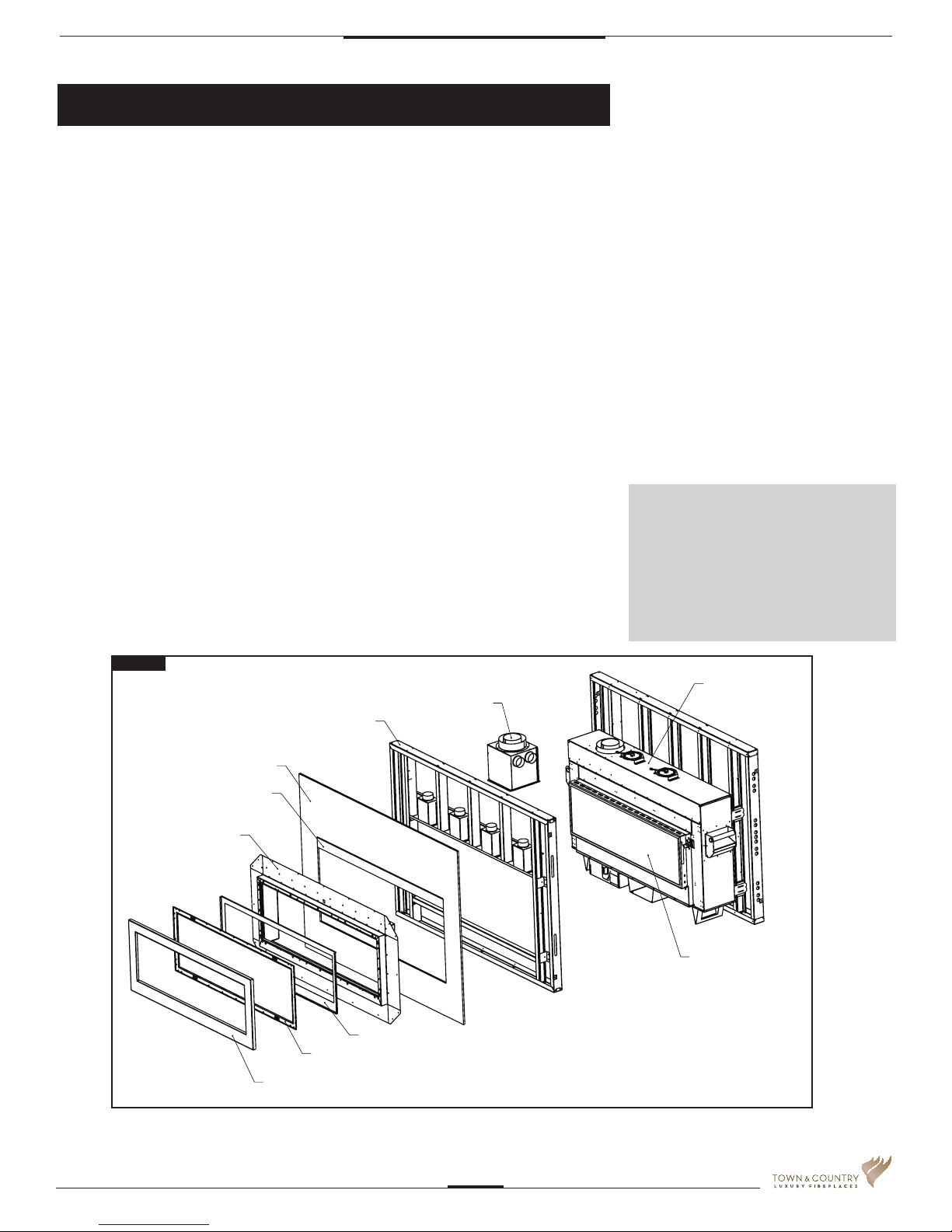
Fig. #10
1/2" CERAMIC PLATE
OUTDOOR BOX WITH
DOUBLE SIDED TAPE
1/2" OSB BOARD
OUTDOOR KIT
METAL FRAMING
OUTER TRIM
INNER TRIM
GLASS ASSEMBLY
JUNCTION BOX
FIREPLACE
OUTDOOR SIDE
Fig 10. Outdoor side. Components and their order of assembly.
TCWS54STOK_061115-56
5055.545-A
9
Stainless steel ashing
Exterior wall
Fig. #11
1/2" OSB board
(factory installed)
Outer window trim
Wall
Use supplied double
sided tape to adhere
house wrap barrier
lm to stainless steel
ashing
Building envelope sealing procedure
sheathing
Seal joint with ashing tape
prior to applying house wrap
barrier lm (not supplied)
Fig 11. Building envelope sealing.
Any type of siding may be used (minimum 120 F rating). See Fig. 12
Note: Local building codes and regulations
may vary. Consult local building
codes prior to installation.
5055.545-A
TCWS54STOK_061115-56
10
Building materials - Outer trim prole view
Fig. #12
Siding material - Max
width: 1 1/2”
Sheathing Panel
House wrap barrier lm
Exterior wall stud
Additional ashing may
be required. Check local
building codes
Outer window trim
Fig 12. Outdoor-side building materials.
TCWS54STOK_061115-56
5055.545-A
11
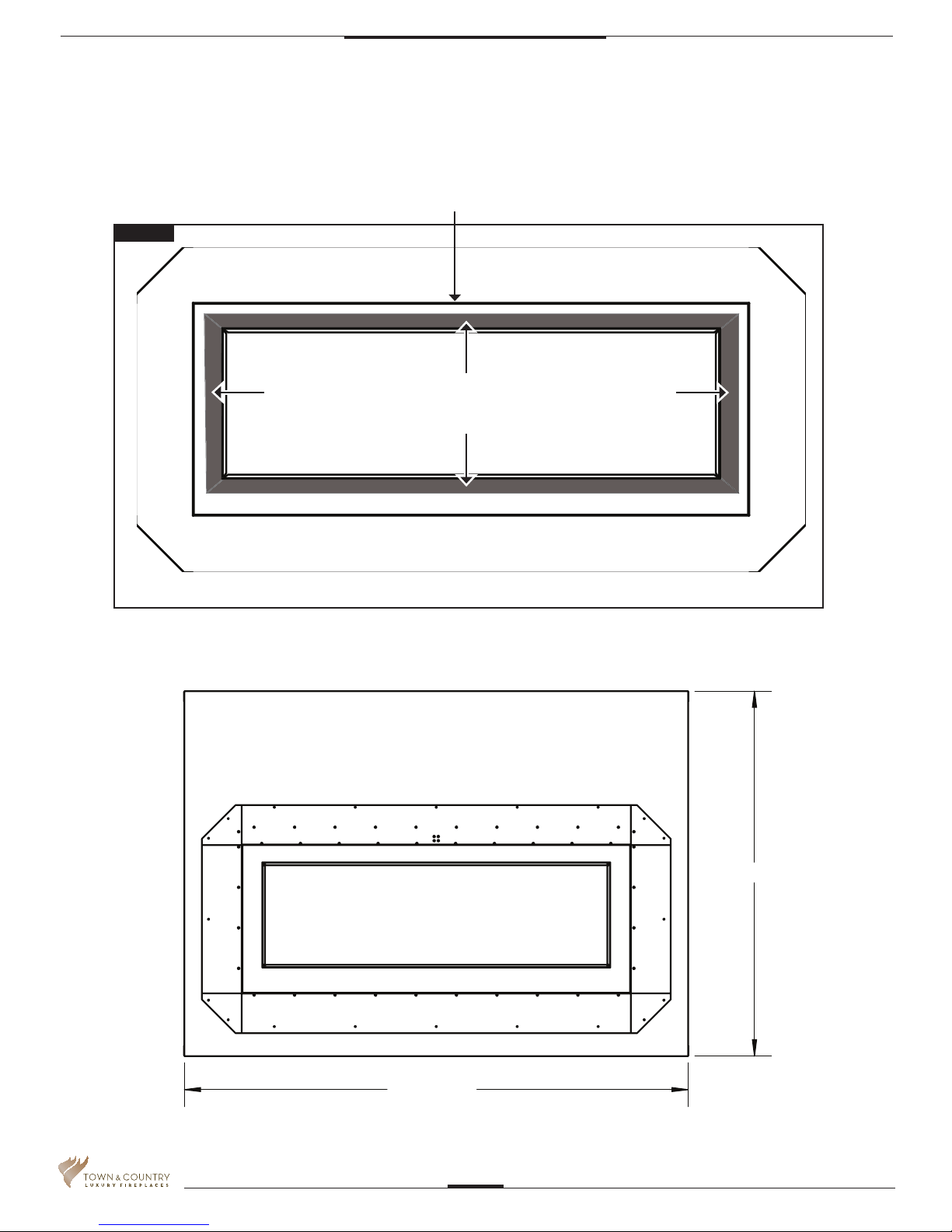
Fig. #13
Tape factory installed over stainless steel anges.
Peel backing from double sided tape
prior to applying house wrap barrier lm.
Fig 13. Double sided tape pre-applied to outdoor box
to keep vapour barrier lm rmly in place.
5055.545-A
54 1/16"
74 3/4"
TCWS54STOK_061115-56
12
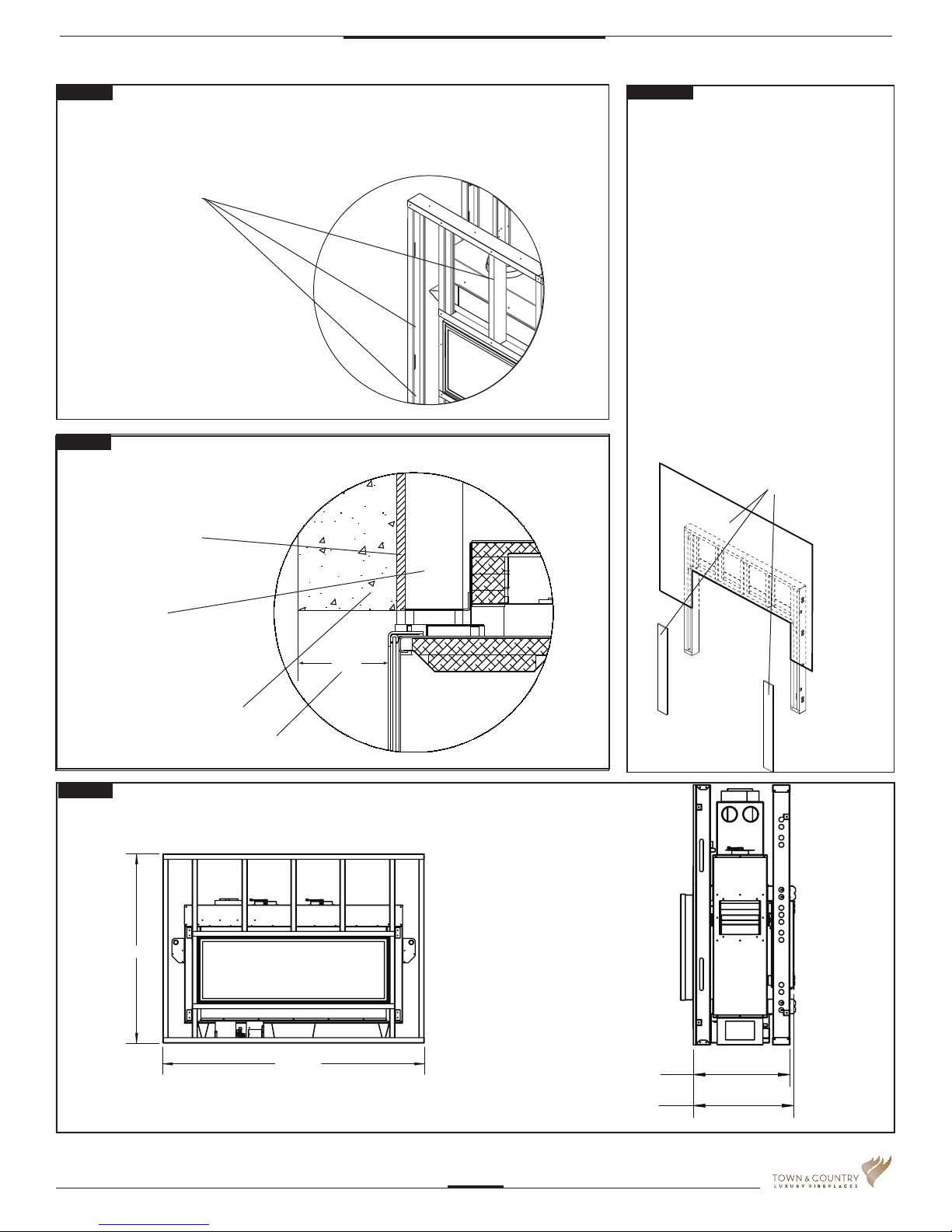
Fig. #14
Fig. #14A
NON-COMBUSTIBLE BOARD DETAIL
NON-COMBUSTIBLE
BOARD ONLY IN
THESE AREAS
NON-COMBUSTIBLE
MATERIAL MUST EXTEND
TO THE TOP EDGE AND TO
THE SIDE EDGE OF THE
FRAMING KIT.
Fig. #15
NON-COMBUSTIBLE RECESSED
INSTALLATION DETAIL
NON-COMBUSTIBLE
BOARD
IF FINISHING THE WALL ABOVE THE UNIT
WITH PAINT, THE FRAMING KIT SHIPPED
WITH THE UNIT SHOULD BE DISCARDED.
USE FULL SHEETS OF CALCIUM
SILICATE BOARD OR EQUIVALENT
AND FULL LENGTH METAL STUDS TO
FINISH AND FRAME AROUND THE UNIT.
CALCIUM SILICATE BOARD IS A HIGH GRADE
MATERIAL WITH CEMENT, QUARTZ AND
NATURAL MINERALS AS THE MAIN RAW
MATERIALS. (NOTE: CALCIUM SILICATE IS
1/2” THICK)
CAUTION: CALCIUM SILICATE BOARD CAN
BE DAMAGED IF DROPPED OR STRUCK.
HANDLE WITH CARE. INSPECT BOARD
PRIOR TO INSTALLATION AND DO NOT USE
IF CRACKED.
NOTE: IT IS RECOMMENDED TO PRE-DRILL
MOUNTING HOLES IN THE BOARD PRIOR
TO SECURING TO THE FRAMING. THIS WILL
PREVENT THE BOARD FROM CRACKING.
CALCIUM SILICATE
BOARD
STEEL STUDS
NON-COMBUSTIBLE
MASONRY TYPE MATERIAL
MAXIMUM FACING DEPTH
Fig. #16
MINIMUM COMBUSTIBLE
FRAMING DIMENSIONS
54 1/16"
4 1/2
74 3/4"
NOTE: FIREPLACE SHOULD BE IN ITS FINAL LOCATION BEFORE FRAMING.
TCWS54STOK_061115-56
20 5/16"
20 13/16" - 23 13/16"
5055.545-A
13
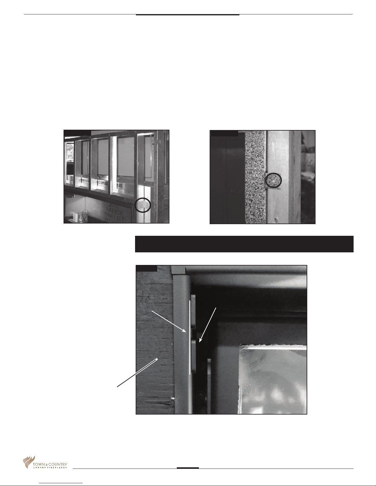
Secure to Existing Framing
Bend out the tabs 90 degrees before inserting the unit into its framed housing (Fig. #18).
•
• Secure the frame assembly to the wood frame through the tabs.
4. Install Non-Combustible Board (not supplied)
• Usedrywallscrews8toinstallthenon-combustibleboard.
Fig. #17
Fig. #18
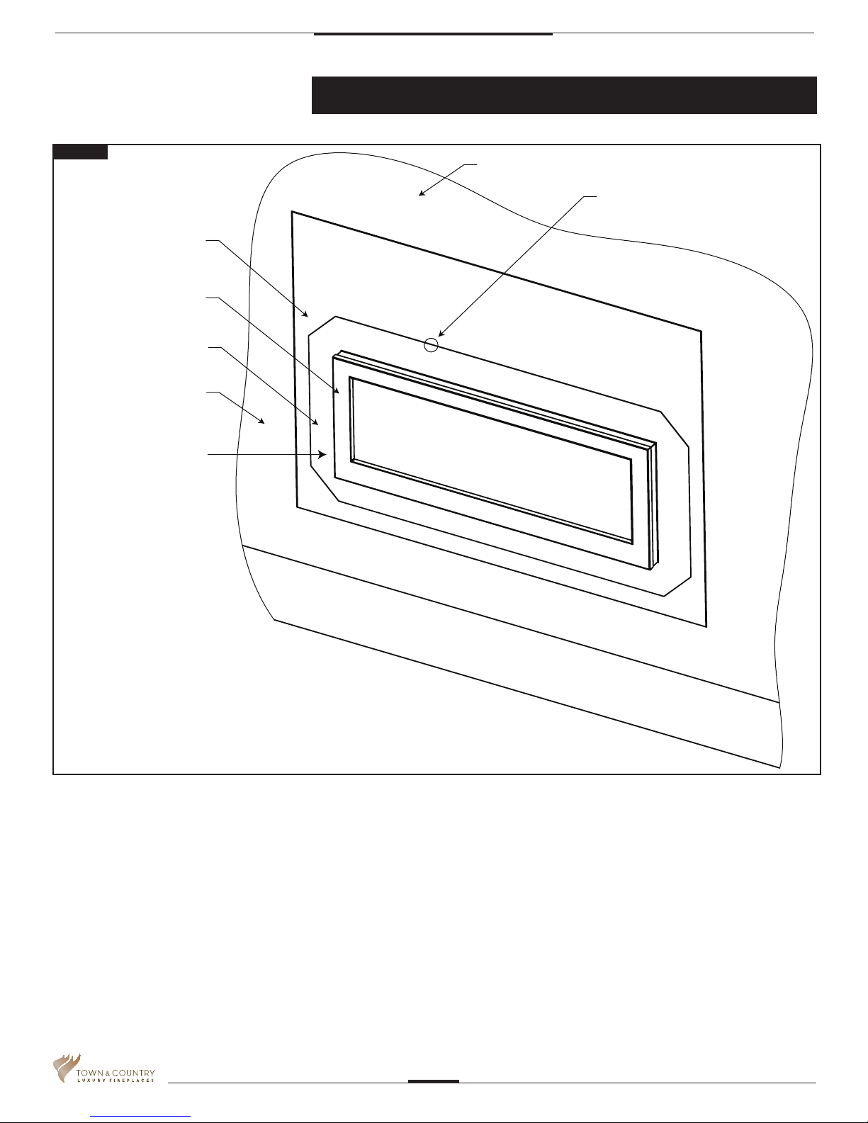
Adjustable Lintel
Fig. #19
This replace may be recessed up to a
maximum depth of 6”, this recess must
Non combustible building
be constructed from non combustible
material may not extend
material. The space between the
past this point
outside lintels and the rebox must be
completely free of any obstructions or
debris and the window with trim tted
must be able to move freely. No build-
ing material is permitted to protrude
past the lintel bars attached to the re-
place under ANY circumstance.
Area inside Lintel must
remain free of obstructions
NON COMBUSTIBLE
FINISH MATERIAL
5055.545-A
NON COMBUSTIBLE
FINISH MATERIAL
TCWS54STOK_061115-56
14
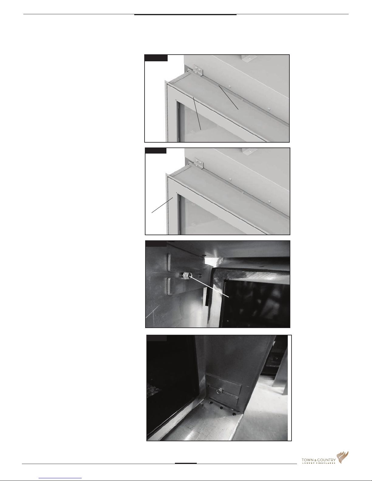
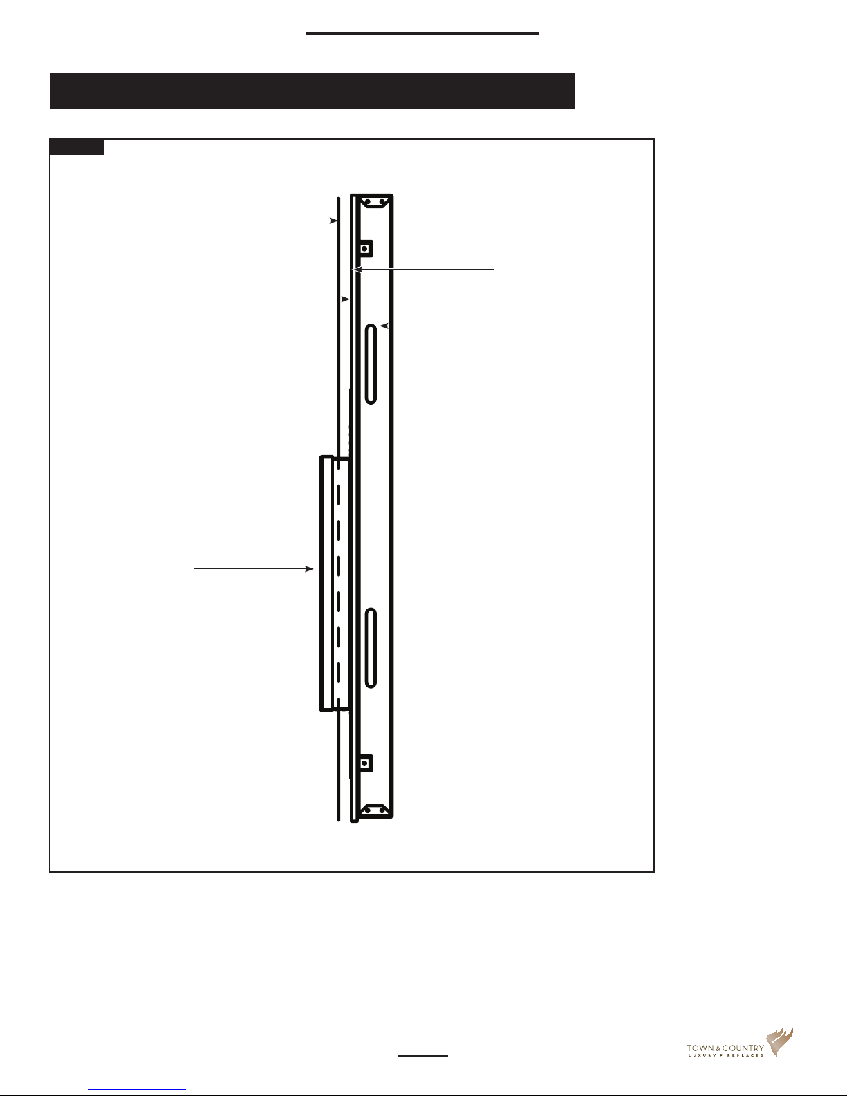
1. The adjustable lintel (Fig #19)
assembly has two orientations for
desired nishing. A anged edge and a
hemmed edge. The lintel comes
factory installed with the ange edge
out. If the desired edge is different from
the factory setting, use the following
steps to change the lintel edge.
Fig. #20
HEMMED EDGE
2. Remove the window trim (Page 6).
3. Loosen the securing bolts in the upper
and lower corners on each side of the
lintel and remove the lintel. Rotate the
assembly to have the desired edge
away from the replace(Fig .#19).
4. The lintel assembly has a maximum
range of adjustability of 1” to
accommodate varying facing material
thicknesses
. (Fig.#21).
5. Adjust the lentil to the desired position.
Tighten the securing bolts.
(Fig.#22 & 23).
6. Re-attach the window trim.
FLANGED EDGE
Fig. #21
SCREEN
Fig. #22
LINTEL
CLAMPING
SCREW
7. Reinstall safety screen.
TCWS54STOK_061115-56
Fig. #23
5055.545-A
15
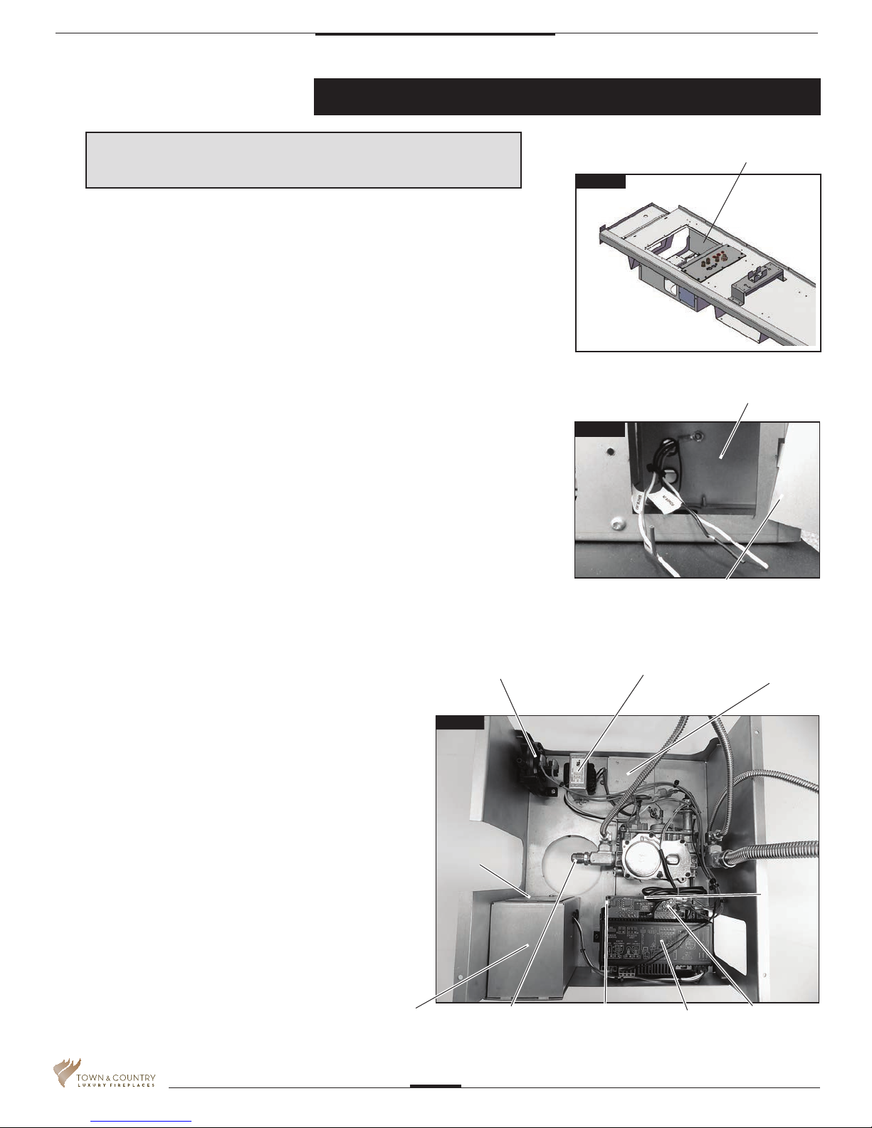
Electrical
Note: Installation must be performed by a qulaied
installer, service agency or gas supplier.
The gas control system is located on the right hand side of the rebox behind an access
panel and the decorative rebox panel (if installed). The replace is operated via a wall
control and a hand held remote control unit.
The wall control is connected to the replace by a 40 ft. communication cable supplied
with the replace.
Installation
1. Place the replace in the desired location.
2. Remove the glass door from the replace.
3. Remove access panel from bottom left hand side of the rebox (Fig #24)
4. Ensure that the switch on the IFC board is set to PV (Power Vent) (Fig #30).
5. Connect 110 V. AC electrical supply to the wires installed inside the junction box
(Fig #24). The replace is rated at 110 volts, 60Hz, 0.25A. The optional power vent kit
is rated at 115 volts, 60Hz, 1.8A.
The electrical wires can be accessed from both inside and outside the junction box by
removing one of the two small access panels (Figs #25 & 26)
6. Attach the wall switch to the framing in the desired
location (Figs #27 & 28). (40 ft is supplied with replace).
FIREBOX ACCESS PANEL
Fig. #24
JUNCTION BOX
Fig. #25
OUTER ACCESS PANEL
7. Route the wall switch control cable as required to the wall
switch (Fig #28).
8. Attach one end of the wall switch control cable to the wall
control. (Fig #27), and the other end to the interface board
(Fig#26)
9. DO NOT INSTALL BATTERIES INTO THE WALL SWITCH.
(FIG #29). BATTERY HOLDER MUST REMAIN EMPTY.
10. If not already installed, install the burner using the instructions
supplied with the burner kit.
11. Turn on the gas supply and check that all connections are tight
and leak free.
12. Turn on gas and electrical supplies.
13. Move the center button on the wall control (Fig #27) to the “ON”
position. The igniter will start to spark. After a short delay
delay, the pilot will light followed by the main burner.
JUNCTION BOX
VACUUM
SWITCH
Fig. #26
INSIDE ACCESS
PANEL
GAS CONNECTOR
TRANSFORMER
WALL SWITCH
CONNECTOR
MODULE
REGULATOR
BOARD
POWER
VENT
SWITCH
INTERFACE BOARD
5055.545-A
TCWS54STOK_061115-56
16
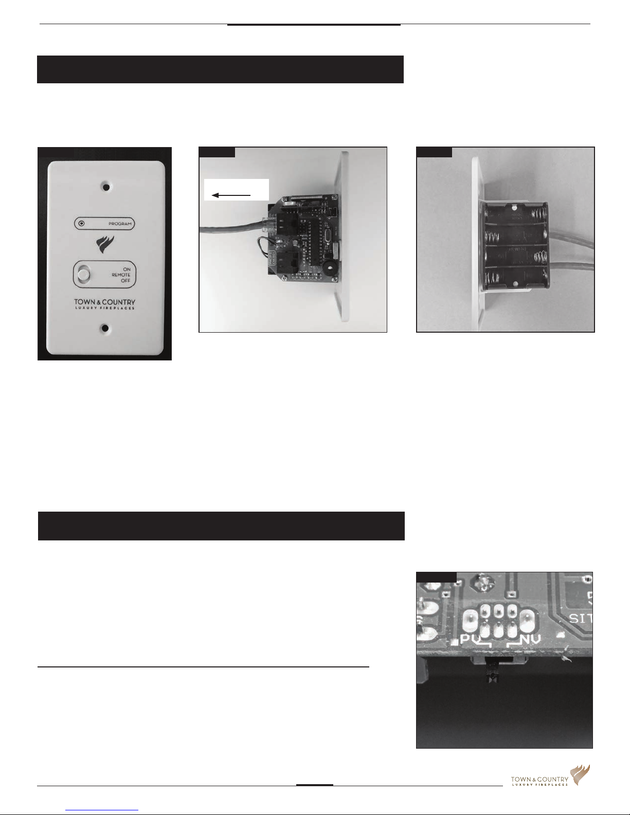
Wall Switch and Remote Control
Note: The wall switch must not have
batteries installed in it. The batteries
are for back up in case of a power
outage. This replace must not
operate with a battery back up.
Fig. #27
Linking the remote control unit to the
wall switch.
1. Begin by moving the selector toggle
on the wall switch to the “REMOTE”
position.
Fig. #28
TO FIREPLACE
2. Insert a straightened paper clip into
the “PROGRAM” slot on the wall
switch.
3. Press the internal “PROGRAM” button
once and wait until you hear 3 beeps
from the wall switch.
Fig. #29
WALL SWITCH WITHOUT BATTERIES
4. Press the ON/OFF button of the
remote unit. Once the wall unit beeps
3 times, the remote is programmed.
5. The toggle on the wall switch must be
kept in the “REMOTE” position in order
to use the remote control unit.
Selecting Natural Vent and Power Vent Modes
The NV / PV (Natural Vent / Power Vent) switch (Fig #30) on the interface board
(Fig #26) is set according to which type of evacuating vent system is present. If the
replace is vented without the assistance of a power vent, the switch should be set to
“NV”. If using a power vent, “PV” should be selected. Follow the
instructions provided with the power vent kit for proper installation.
The TCWS54STOK_D must be pre-set to the “PV” setting.
TCWS54STOK_061115-56
Fig. #30
5055.545-A
17
 Loading...