

Town & Country Fireplaces TCWS54ST Installation And Operating Instructions Manual
INSTALLER: Leave this manual with the appliance.
CONSUMER: Retain this manual for future reference.
WARNING: If the information in these
instructions is not followed exactly, a re or
explosion may result causing property damage,
personal injury or death.
FOR YOUR SAFETY
Installation and service must be performed
by a quali ed installer, service agency or the
gas supplier.
WHAT TO DO IF YOU SMELL GAS
• Do not try to light any appliance.
• Do not touch any electrical switch.
• Do not use any phone in your building.
• Immediately call your gas supplier from
a neighbour’s phone. Follow the gas
supplier’s instructions.
• If you cannot reach your gas supplier call
the re department.
SERIAL #
TCWS.54CSTE
INSTALLATION
Do not store or use gasoline or other ammable
vapours and liquids in the vicinity of this or
any other appliance.
This appliance may be installed in an aftermarket
permanently located, manufactured home (USA
only) or mobile home, where not prohibited by
local codes.
This appliance is only for use with the type of gas
indicated on the rating plate. This appliance is
not convertible for use with other gases, unless
a certi ed kit is used.
This appliance is suitable for installation in a
bedroom or bed sitting room.
AND OPERATING
INSTRUCTIONS
MODEL
TCWS54ST
SERIES C
POWER VENTED
SEE THRU FIREPLACE
110712-72 TCWS.54CSTE 5056.425218

Table of Contents
Table of Contents
Table of Contents ............................................................................2
Table of Contents ............................................................................3
Certi cations ...................................................................................3
Caution ...........................................................................................4
Safety .............................................................................................4
Important Note for the Commonwealth of Massachusetts: ............. 5
Fireplace Dimensions .....................................................................6
Minimum Clearances to Combustible Material ...............................6
Installation Requirements ...............................................................7
Manufactured (Mobile) Home .........................................................7
Window Frame Removal ................................................................. 7
Standoffs.........................................................................................8
Locating The Fireplace ...................................................................8
Framing and Finishing ....................................................................9
Steel Stud Framing Kit .................................................................. 11
Adjustable Lintel ...........................................................................14
Maestro Control ........................................................................... 15
Plumbing and Electrical ................................................................ 15
Gas Supply ................................................................................... 18
Gas Pressure Check ..................................................................... 18
Venting .......................................................................................... 19
Venting Components ....................................................................19
TCVT.PVOFM Power Vent Installation .......................................... 20
Contents of Power Vent Kit ...........................................................20
Venting Con gurations..................................................................20
Minimum Vent Length Chart .........................................................21
Vent Terminal Minimum Clearances ............................................. 21
Horizontal (Side Wall) Venting ......................................................22
Fan Wiring .................................................................................... 24
Terminal Dimensions .................................................................... 25
Wiring Diagram .............................................................................26
TCVT.PVOFM3 Power Vent Installation ........................................ 27
Contents of Power Vent Kit ...........................................................27
Venting Con gurations..................................................................27
Terminal Dimensions .................................................................... 28
Horizontal (Side Wall) Venting ......................................................28
Fan Wiring .................................................................................... 30
Wiring Diagram .............................................................................31
TCVT.PVOB2 Power Vent Installation ........................................... 32
Contents of Power Vent Kit ...........................................................32
Venting Con gurations..................................................................32
Horizontal (Side Wall) Venting ......................................................33
Vent Terminal Minimum Clearances ............................................. 33
Vertical (Through Roof) Venting .................................................... 34
Vertical (Through Roof) Venting .................................................... 35
TCWS.54CSTE 110712-72
2

Table of Contents
Wiring Diagram .............................................................................36
Vent Pipe Sealant .........................................................................37
Optional Tranquility Burner ........................................................... 38
Propane Conversion .....................................................................44
Optional Black Diamond Burner ...................................................47
Gas Pressure Check ..................................................................... 51
Burner Flame Adjustment .............................................................52
Firebox Panels Installation ............................................................ 53
Finishing Touch Trim Kit Instructions ............................................. 54
Lighting Instructions .....................................................................55
First Fire ........................................................................................ 55
Maestro Control System ...............................................................56
Remote Control Initial Setup .........................................................56
Maestro Control System - Operation ............................................57
Maintenance ................................................................................. 60
Replacement Parts - TCWS.54CSTE ........................................... 61
Replacement Parts - Tranquility Burner ........................................ 62
Replacement Parts - Black Diamond Burner ................................63
Replacement Parts - TCVT.PVOFM .............................................64
Replacement Parts - TCVT.PVOFM3 ...........................................65
Replacement Parts - TCVT.PVOB2 ..............................................66
Replacement Parts – Maestro Control System ............................. 67
Wiring Diagram .............................................................................68
Light Wiring Diagrams .................................................................. 69
Safety Label Location ................................................................... 71
Certi cations
This appliance is tested to:
ANSI Z21.50b-2009 / CSA 2.22b-2009 Vented Gas Fireplaces.
CAN/CGA 2.17-M91 Gas-Fired Appliance For Use At High Altitudes.
CSA P.4.1 Annual Fireplace Efficiency 30.8%
Maximum Setting input 63.881 Btu/Hr, output 19,675 Btu/Hr
Minimum Setting input 39,418 Btu/Hr, output 12,141 Btu/Hr
This unit is manufactured and tested by:
Paci c Energy Fireplace Products
2975 Allenby Rd.
Duncan, BC, Canada
V9L 6V8
TCWS.54CSTE 110712-72
3

Caution
FOR YOUR SAFETY - Do not install or operate your Town & Country replace without
rst reading and understanding this manual. Any installation or operational deviation from
the following instructions voids the Town & Country Fireplaces
hazardous.
This appliance and its individual shut off valve must be disconnected from gas supply piping system during any pressure testing of that system at test pressures in excess of 1/2
psig (3.5 kPa).
This appliance must be isolated from the gas supply piping system by closing its individual
manual shut off valve during any pressure testing of the gas supply piping system at test
pressures equal to or less than 1/2 psig (3.5 kPa).
TM
Warranty and may prove
Note: When lit for the rst time, the appliance will emit a slight odour for a couple of hours.
This is due to the curing of paints, sealants and lubricants used in the manufacturing process.
This condition is temporary. Open doors and windows to ventilate area. Smoke and fumes
caused by the curing process may cause discomfort to some individuals.
Do not use the replace if any part has been under water. Immediately call a quali ed service
technician to inspect the replace and to replace any part of the control system and any gas
control which has been under water.
Safety
Due to high temperatures, this gas appliance should be located out of traffic and away from
furniture and draperies.
Children and adults should be alerted to the hazards of high surface temperatures and
should stay away to avoid burns or clothing ignition.
Young children should be carefully supervised when they are in the same room as the
appliance.
Clothing or other ammable material should not be placed on or near the appliance.
Any grill, panel or door removed for servicing the unit must be replaced prior to operating.
Failure to do so may create a hazardous condition.
We recommend that our gas hearth
products be installed and serviced
by professionals who are certi ed
in the United States by the National
Fireplace Institute
Specialists
®
(NFI) as NFI Gas
Installation and repair should be done by a quali ed service person. The appliance should
be inspected before use and at least annually by a professional service person. More
frequent cleaning may be required due to excessive lint from carpeting, bedding material,
etc. It is imperative that control compartments, burners and circulating air passageways of
the appliance be kept clean.
It is our policy that no responsibility is assumed by the Company or by any of its employees
or representatives for any damages caused by an inoperable, inadequate, or unsafe
condition which is the result, either directly or indirectly, of any improper operation or
installation procedures.
This appliance must not be connected to a chimney ue serving a separate solid fuel
burning appliance.
TCWS.54CSTE 110712-72
4

Important Note for the Commonwealth of Massachusetts:
From Massachusetts Rules and Regulations 248 CMR 5.08:
(a) For all side wall horizontally vented gas fuelled equipment installed in every dwelling, building or structure used in whole or in part for residential
purposes, including those owned or operated by the Commonwealth and where the side wall exhaust vent termination is less than seven (7) feet above
nished grade in the area of the venting, including but not limited to decks and porches, the following requirements shall be satis ed.
1. INSTALLATION OF CARBON MONOXIDE DETECTORS. At the time of installation of the side wall horizontal vented gas fuelled equipment, the
installing plumber or gas tter shall observe that a hard wired carbon monoxide detector with an alarm and battery back-up is installed on the oor level
where the gas equipment is to be installed, in addition, the installing plumber or gas tter shall observe that a battery operated or hard-wired carbon
monoxide detector with an alarm is installed on each additional level of the dwelling, building or structure served by the side wall horizontal vented gas
fuelled equipment. It shall be the responsibility of the property owner to secure the services of quali ed licensed professionals for the installation of
hard-wired carbon monoxide detectors.
a. In the event that the side wall horizontally vented gas fuelled equipment is installed in a crawl space or an attic, the hard-wired carbon monoxide
detector with alarm and battery back-up may be installed on the next adjacent oor level.
b. In the event that the requirements of this subdivision cannot be met at the time of completion of installation, the owner shall have a period of thirty
(30) days to comply with the above requirements; provided, however, that during said thirty (30) day period, a battery operated carbon monoxide detector with an alarm shall be installed.
2. APPROVED CARBON MONOXIDE DETECTORS. Each carbon monoxide detector as required in accordance with the above provisions shall
comply with NFPA 720 and be ANSI/UL 2034 listed as IAS certi ed.
3. SIGNAGE. A metal or plastic identi cation plate shall be permanently mounted to the exterior of the building at a minimum height of eight (8) feet
above grade directly in line with the exhaust vent terminal for the horizontally vented gas fuelled heating appliance or equipment. The sign shall read, in
print size no less than one-half (1/2) inch in size, “GAS VENT DIRECTLY BELOW. KEEP CLEAR OF ALL OBSTRUCTIONS”.
4. INSPECTION. The state or local gas inspector of the side wall horizontally vented gas fuelled equipment shall not approve the installation unless,
upon inspection, the inspector observes carbon monoxide detectors and signage installed in accordance with the provisions of 248 CMR 5.089(2)(a) 1
through 4.
(b) EXEMPTIONS. The following equipment is exempt from 248 CMR 5.089(2)(a) 1 through 4.
1. The equipment listed in Chapter 10 entitled “Equipment Not Required To Be Vented” in the most current edition of NFPA 54 as adopted by the
Board; and
2. Product Approved side wall horizontal vented gas fuelled equipment installed in a room or structure separate from the dwelling, building or structure used in whole or in part for residential purposes.
(c) MANUFACTURER REQUIREMENTS – GAS EQUIPMENT VENTING SYSTEM PROVIDED. When the manufacturer of Product Approved side
wall horizontally vented gas equipment provides a venting system design or venting system components with the equipment, the instructions provided by
the manufacturer for installation of the equipment and the venting system shall include:
1. Detailed instructions for the installation of the venting system design or the venting system components; and
2. A complete parts list for the venting system design or venting system.
(d) MANUFACTURER REQUIREMENTS – GAS EQUIPMENT VENTING SYSTEM NOT PROVIDED. When the manufacturer of a Product Approved
side wall horizontally vented gas fuelled equipment does not provide the parts for venting the fuel gases, but identi es “special venting systems”, the following requirements shall be satis ed by the manufacturer.
1. The referenced “special venting system” instructions shall be included with the appliance or equipment installation instructions; and
2. The “special venting systems” shall be Product Approved by the Board, and the instructions for that system shall include a parts list and detailed
installation instructions.
(e)) A copy of all installation instructions for all Product Approved side wall horizontally vented gas fuelled equipment, all venting instructions, all parts
lists for venting instructions, and/or all venting design instructions shall remain with the appliance or equipment at the completion of the installation.
TCWS.54CSTE 110712-72
5
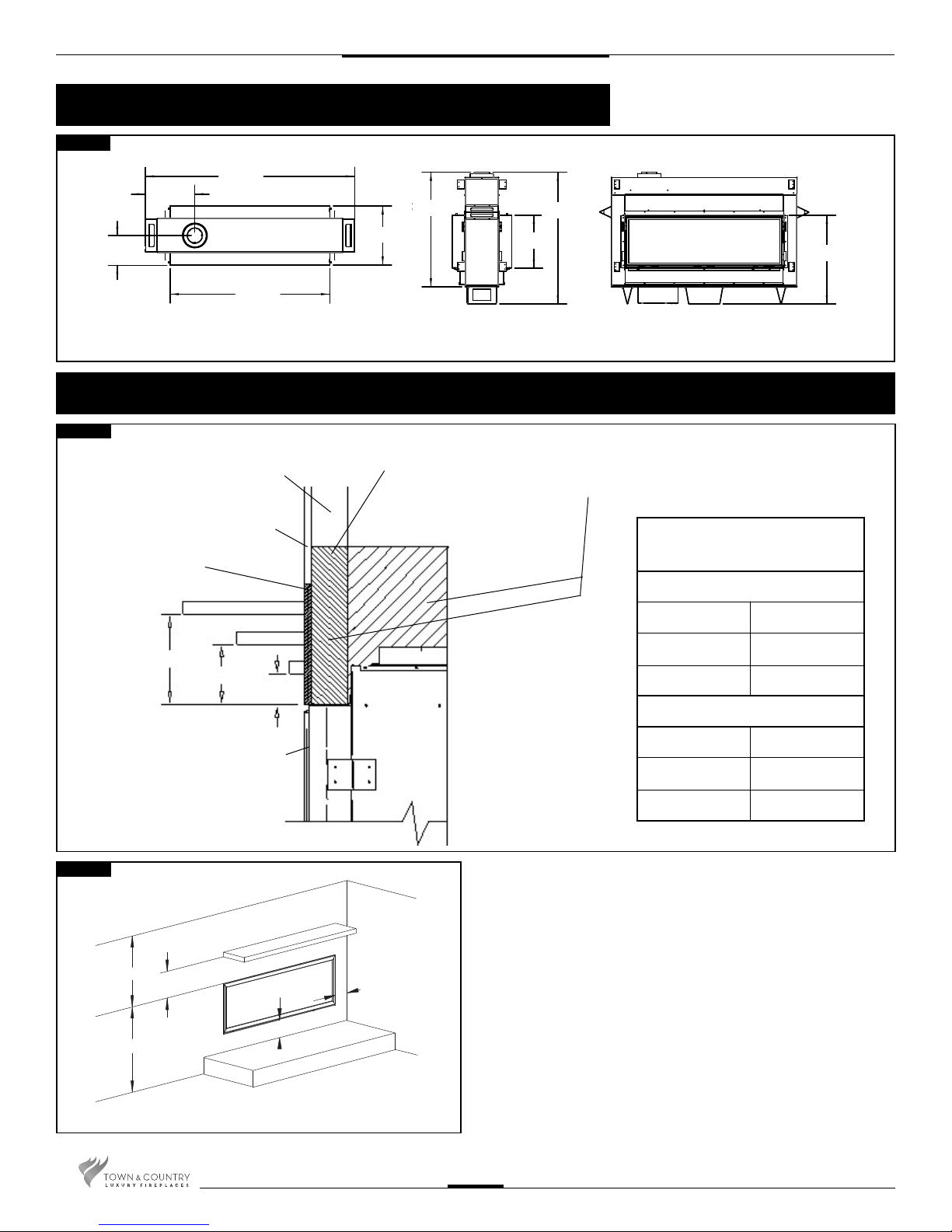
Fireplace Dimensions
Fig. #1
70 3/4”
16 9/16”
10”
53 3/4”
19 7/8”
35 5/8”
41 1/4”
18”
Minimum Clearances to Combustible Material
30 1/16”
Fig. #2
COMBUSTIBLE FRAMING AND
FINISH WALL ABOVE STANDOFFS
MAY USE COMBUSTIBLE
FACING MATERIAL IN THIS AREA
NON-COMBUSTIBLE
FINISH MATERIAL
SEE FIG #8 & 9
A
B
TOP OF LINTEL BAR
FIREPLACE FRONT
Fig. #3
CEILING
24"
*
29 3/4"
COMBUSTIBLE FLOOR
STEEL FRAMING
D
E
F
C
ADJACENT WALL
OR MANTEL SUPPORT
4“
6”
COMBUSTIBLE HEARTH
UNIT MAY BE RECESSED UP TO 6” WITH
NONCOMBUSTIBLE MASONRY TYPE MATERIAL
NON-COMBUSTIBLE ZONE.
DO NOT INSTALL ANY COMBUSTIBLE MATERIAL, ELECTRICAL WIRING OR GAS PLUMBING
IN THIS AREA.
MANTEL CLEARANCE
CHART
* MANTEL CLEARANCE
A 9”
B 6”
C 3”
** MANTEL DEPTH
D 12”
E 6 3/4”
F 1 1/2”
Minimum Clearances:
Side standoffs ....................................................... 0 in. (0 mm)
Back standoffs ...................................................... 0 in. (0 mm)
Top standoffs ........................................................0 in. (0 mm)
Bottom of appliance .............................................. 0 in. (0 mm)
Adjacent side wall ................................................. 4 in. (102 mm)
Ceiling to appliance ............................................24 in. (610 mm)
*Mantel to appliance ................... ..........See Figure #2
**Maximum Mantel extension ..... ..........See Figure #2
Mantel support ...................................................... 4 in. (102 mm)
Vent pipe .......................................................1 3/4" in. (45 mm)
TCWS.54CSTE 110712-72
6
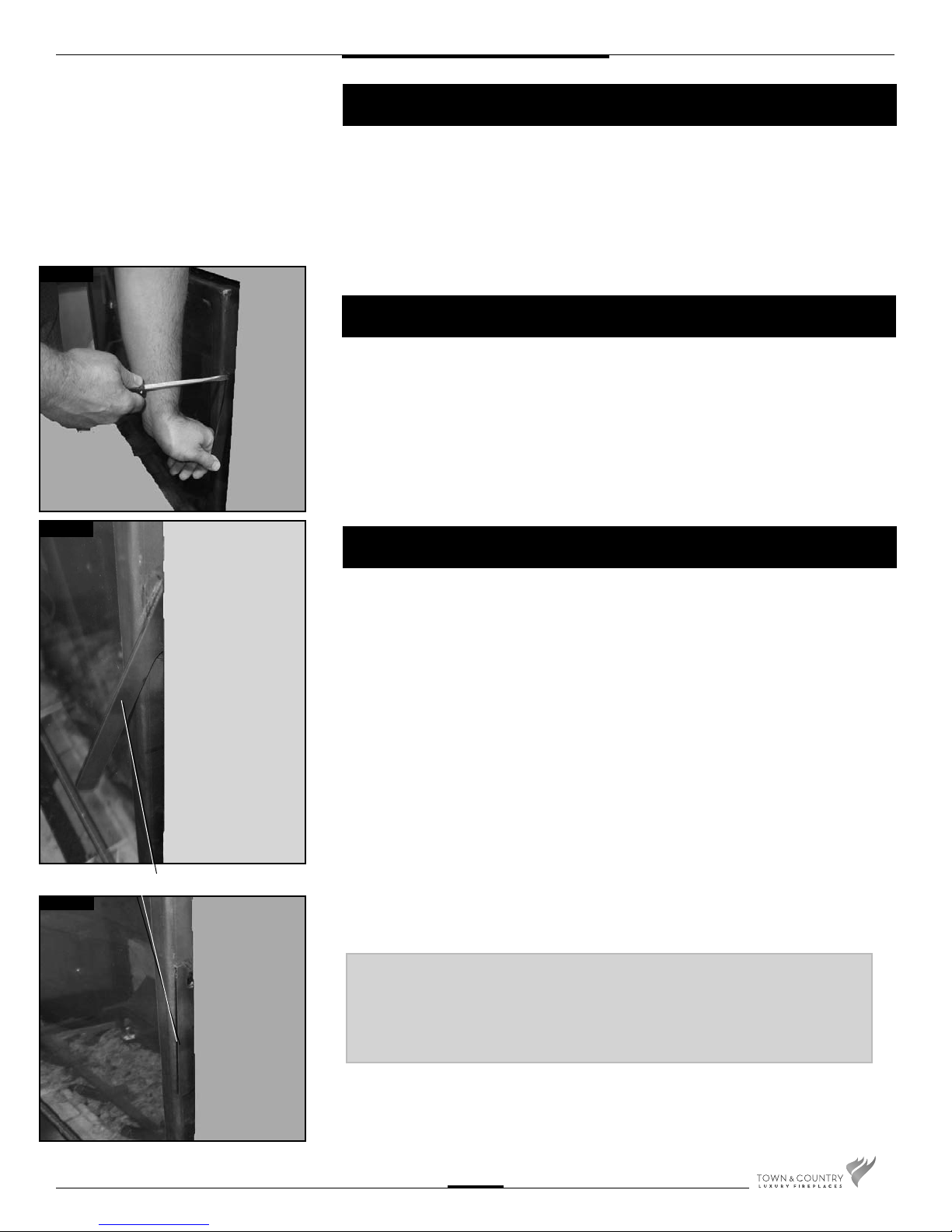
Fig. #4
Fig. #5
Installation Requirements
The Town & Country Fireplace installation and venting must conform to the local codes
or, in the absence of local codes, current CSA B149.1 installation code (in Canada) or
the current National Fuel Gas Code, ANSI Z223.1/NFPA 54 (in the USA). Only quali ed
(licensed or trained) personnel should install this product.
In the state of Massachusetts, only a licensed Plumber and Gas Fitter may install
this product.
Manufactured (Mobile) Home
In some jurisdictions, the Town & Country Fireplace may be installed in Manufactured
Homes after the " rst sale". Consult local codes for approval. The replace must be
fastened in place.
Install in accordance with the current standard Mobile Homes, CAN/CSA Z240 MH (in
CANADA), and the Manufacturer's Home Construction and Safety Standard, Title 24 CFR,
Part 3280 or the current Standard for Fire Safety Criteria for Manufactured Home Installations, Sites and Communities ANSI/NFPA 501A (in the USA).
Window Frame Removal
Fig. #5a
LATCH HANDLE
Warning: Turn off the replace, and allow ample time for the unit to cool before
proceeding.
Caution: The ceramic glass is very fragile, and should be handled with care.
The window frame is held in place by two spring-loaded latches that are operated by a
one-piece latch handle.
1. Remove the TC Finishing Touch Trim Kit from the window frame. (If installed)
2. Using a screwdriver or other similar object, push against the notch in the top of the
latch and grab the bottom of the latch handle as it protrudes. Lift handle until latch hook
disengages. Repeat for other side while holding glass so it does not tip out. Fig #4, 5 &
5a.
3. Tilt the top of the window frame out to clear the top edge of the unit. Grasp the sides of
the frame and lift up and out to disengage from its bottom track.
4. Place the window frame in a safe place to avoid damage.
5. Re-assemble in reverse order. Latch handle should snap into place and be ush with
window frame when engaged correctly.
TIP:
To ensure glass is properly latched, grasp the top left and
right sides of the glass frame, under moderate pressure it
should pull forward and return to original position evenly on
both sides.
TCWS.54CSTE 110712-72
6. Reinstall Trim Kit if required.
7
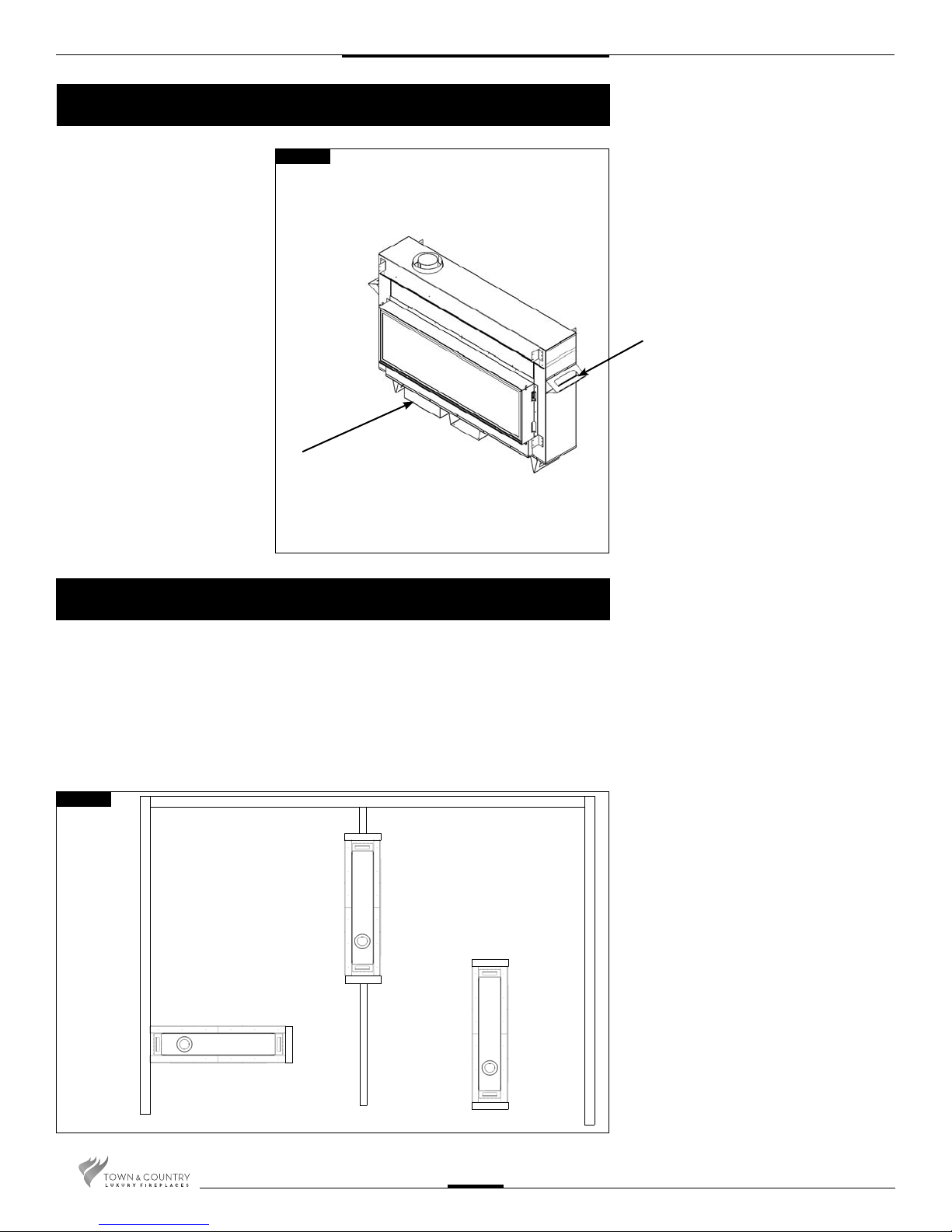
Standoffs
The framing kits, once assembled
and attached, are used as the
top and side standoffs (see page
10 & 11.)
Fig. #6
CONTROL
BOX
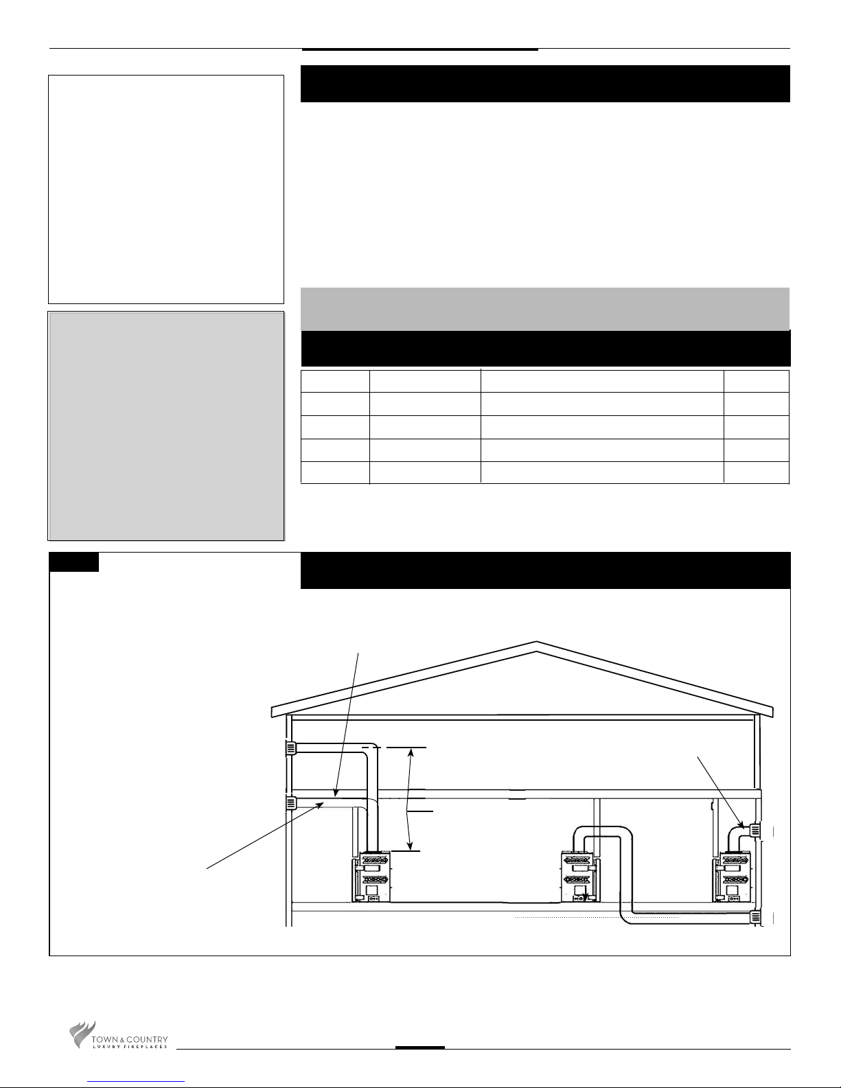
Locating The Fireplace
HANDLE
In planning the installation for the replace, it is necessary to determine where the unit is to
be installed, location of vent system and where gas supply piping may be plumbed. Various
types of installations are possible, such as, a peninsula wall, an island, and between two
interior walls (Fig. #7). Due to high temperatures, do not locate this replace in areas of high
traffic or near furniture or draperies.
The minimum clearances from the replace to combustible surfaces must be adhered
to and are shown in Fig. #2 and Fig. #3.
Fig. #7
EXAMPLES OF COMMON
LOCATIONS SEE FIG #11 FOR
DIMENSIONS
TCWS.54CSTE 110712-72
8
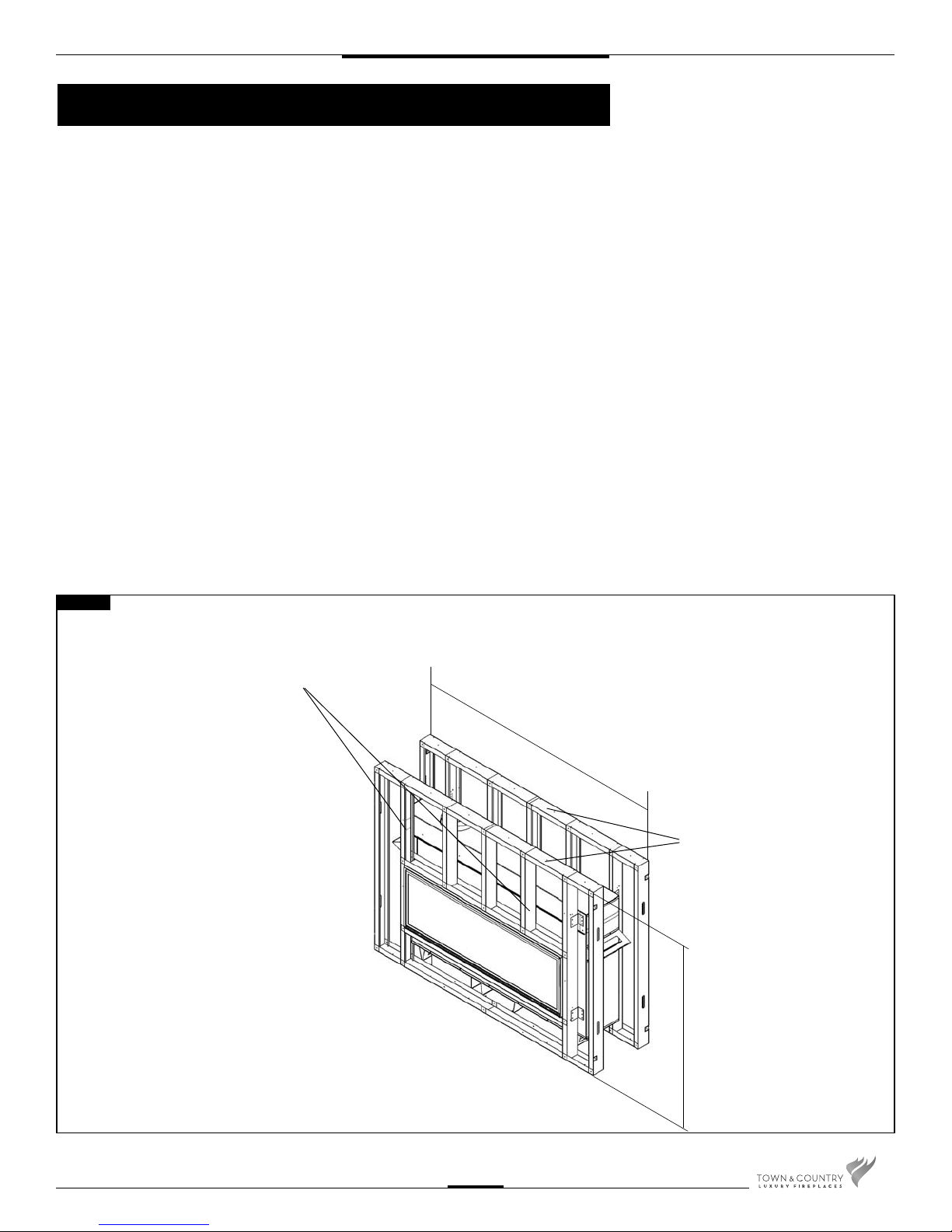
Framing and Finishing
Note: The replace should be in place
and venting installed before framing in
or building an enclosure around the unit.
When the appliance is installed directly on
carpeting, tile or other combustible material,
other than wood ooring, the appliance shall
be installed on a metal or wood panel extending the full width and depth of the appliance.
The Town & Country replace must be framed
in as described below or totally enclosed with
non-combustible material, such as
facing brick.
Determine the total thickness of facing
material to be used. A thickness of 3/4" will
allow the nishing surface to be ush with
the front of the unit. If preferred, additional
masonry type non-combustible material can
be installed above and to the sides up to 6
inches forward of the appliance.
*The nishing material must not interfere
with glass frame access.*
A Steel Stud Framing Kit is supplied with the
replace and must be used unless the
replace is totally enclosed with
non-combustible material. Assemble the
framing kit as per the instructions on pages
10 – 12 of this manual. Attach the steel frame
to the replace once the replace is in its nal
position. Secure the steel frame to the framing
brackets on each side of the unit. Ensure that
the studs are set back far enough to allow for
thickness of nishing surface.
The sides and top of the replace can
be framed in up to the steel studs using
conventional lumber. Consult local building
codes for speci c requirements.
Due to high temperatures, non-combustible
backer board, such as cement board or its
equivalent, must be used to sheet in the front
of the replace. (Fig. #9) Standard sheetrock
(dry wall) may be used beyond this.
If the backer board is not to be nished with
other non-combustible material such as tiles,
it is recommended that top sections of the
framing kit be covered with a single sheet
of calcium silicate board or its equivalent.
Taped and mudded joints may crack due to
the elevated temperatures.
Chase Insulation: When installing this
replace against a non-insulated exterior
wall or chase, it is recommended that the
outer walls be insulated to the same degree
as other exterior walls. Do not place replace
directly against the insulation. Cover the
insulation and plastic vapour barrier with a
solid surface, such as dry wall (sheetrock).
Consult local codes. Do not insulate or use
plastic vapour barrier within the framing kit.
CAUTION: SEE FIGURE #9a BEFORE
PROCEEDING.
Fig. #8
NON-COMBUSTIBLE ZONE. DO NOT INSTALL ANY
COMBUSTIBLE MATERIAL, ELECTRICAL WIRING,
INSULATION, PLASTIC VAPOR BARRIER OR GAS
PLUMBING WITHIN THE STEEL STUD FRAMING
STEEL STUD FRAMING KIT DIMENSIONS
(Supplied with replace)
ALL OTHER FRAMING CAN
BE DONE WITH
CONVENTIONAL LUMBER
74 5/8”
IT IS HIGHLY RECOMMENDED THAT
A FULL HEADER BE INSTALLED
ABOVE THE FRAMING KIT
54 1/16”
TCWS.54CSTE 110712-72
9
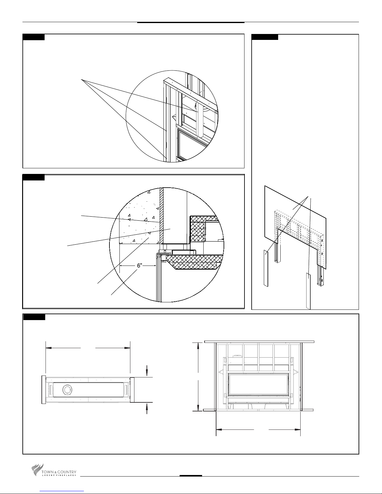
Fig. #9
NON-COMBUSTIBLE BOARD DETAIL
NON-COMBUSTIBLE
BOARD ONLY IN
THESE AREAS
NON-COMBUSTIBLE
MATERIAL MUST EXTEND
TO THE TOP EDGE AND TO
THE SIDE EDGE OF THE
FRAMING KIT.
Fig. #10
NON-COMBUSTIBLE RECESSED
INSTALLATION DETAIL
NON-COMBUSTIBLE
BOARD
Fig. #9A
IF FINISHING THE WALL ABOVE THE UNIT
WITH PAINT, THE FRAMING KIT SHIPPED
WITH THE UNIT SHOULD BE DISCARDED.
USE FULL SHEETS OF CALCIUM SILICATE
BOARD AND FULL LENGTH METAL STUDS
TO FINISH AND FRAME AROUND THE UNIT.
CALCIUM SILICATE BOARD IS A HIGH GRADE
MATERIAL WITH CEMENT, QUARTZ AND
NATURAL MINERALS AS THE MAIN RAW
MATERIALS. (NOTE: CALCIUM SILICATE IS
1/2” THICK)
CAUTION: CALCIUM SILICATE BOARD CAN
BE DAMAGED IF DROPPED OR STRUCK.
HANDLE WITH CARE. INSPECT BOARD
PRIOR TO INSTALLATION AND DO NOT USE
IF CRACKED.
NOTE: IT IS RECOMMENDED TO PRE-DRILL
MOUNTING HOLES IN THE BOARD PRIOR
TO SECURING TO THE FRAMING. THIS WILL
PREVENT THE BOARD FROM CRACKING.
CALCIUM SILICATE
BOARD
STEEL STUDS
NON-COMBUSTIBLE
MASONRY TYPE MATERIAL
MAXIMUM FACING DEPTH
Fig. #11
MINIMUM COMBUSTIBLE
FRAMING DIMENSIONS
INCLUDING SHEETROCK
74 7/8"
54 5/16"
20"
NOTE: FIREPLACE SHOULD BE IN ITS FINAL LOCATION BEFORE FRAMING.
74 7/8"
TCWS.54CSTE 110712-72
10
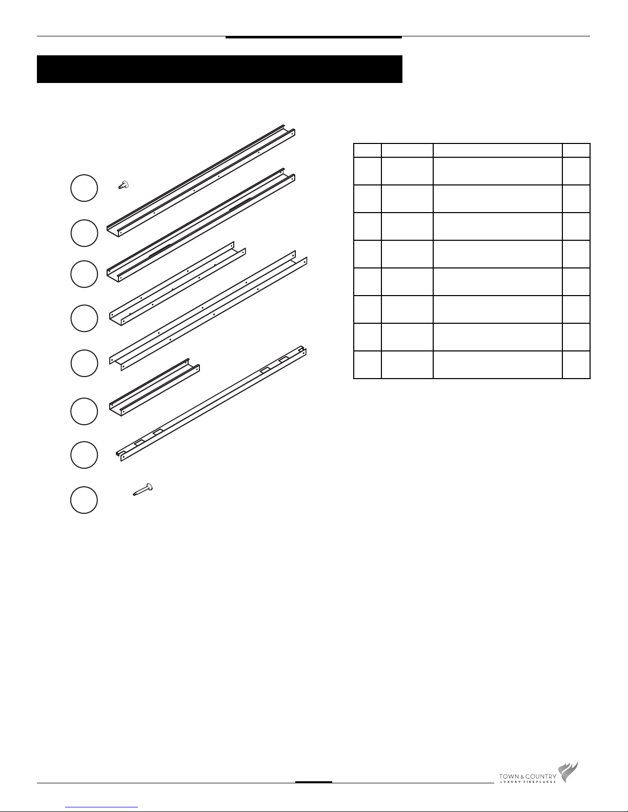
Steel Stud Framing Kit
Each Kit Contains:
1
2
TCWS.54STFRKIT
Item Part # Description Qty.
1 5049.9912 SCREW, WAFER #8 x 1/2 Pkg
2 8493.4 STUD, SIDES 54” L 2
3 8493.2 STUD, OUTER SIDES 54” L 2
4 8493 STUD, UPPER/LOWER
40
4
38 1/16” L
3
4
5
6
7
8
5 8493.6 INNER CROSS BRACE
56 7/8” L
6 8493.8 STUD, CENTER 24” L 3
7 8293.9 LOWER CROSS BRACE
56 7/8” L
8 5049.993 SCREW, DRYWALL, 1 1/4” Pkg
1
1
30
TCWS.54CSTE 110712-72
11
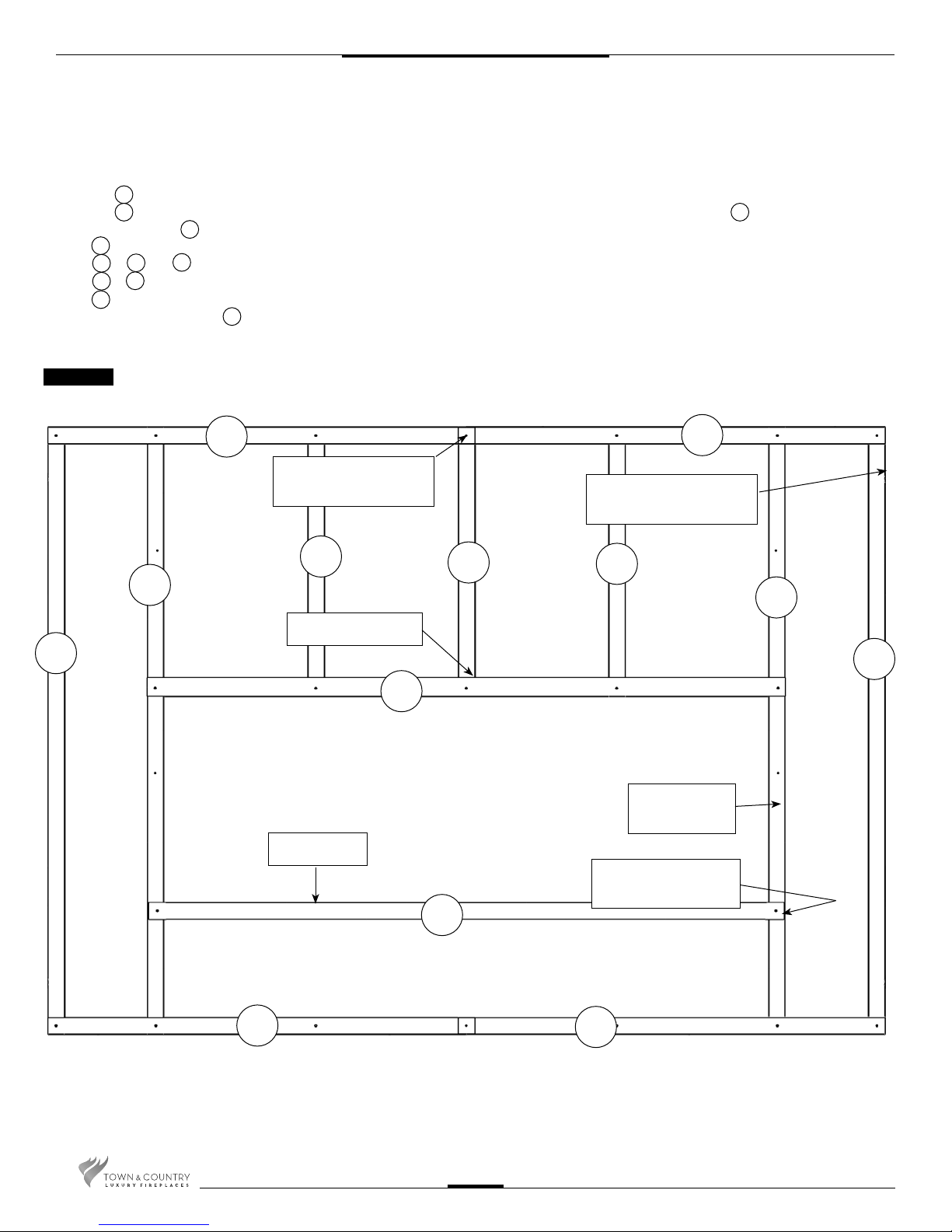
NOTE: Sheet metal parts have sharp edges, use caution when handling.
1. Frame Assembly
• Place 2 of #4 together as a top.
• Place 1 of #6 into the joint with the long edge facing up. Align the 3 holes and screw together with wafer screw #1.
• Attach the remaining #6 in the same manner at holes to the left and right of the center.
• Attach #2 with wide edge face up.
• Attach #5 to #6 and #2.
• Attach #7 to #2 using 1 screw through the top and 1 screw through the side at each end.
• Attach #3 , 1 on each side with bend out tabs to the front.
• Place 2 remaining pieces of #4 together at the bottom of the framing kit in the same manner as the top, screw them together and attach to
the inner steel studs.
4
6
6
2
2
6
5
2
7
3
4
1
• Turn the framing kit over and secure all studs from the back.
Fig. #12
4
SCREW THROUGH
3 LAYERS
2
LONG EDGE UP
3
6
FRONT VIEW
4
BEND OUT FRAMING
TABS TO FRONT
6
6
2
3
SLOTS UP
4
5
WIDE FACE
FORWARD
SCREW INTO
SIDE
7
4
TCWS.54CSTE 110712-72
12
2. Attach the Assembled Frame to the
Unit
• Align the assembled frame to the unit
framing brackets. (Fig #13) Attach at
the fastening points through the
access holes in the outer side studs
(3).
3. Secure to Existing Framing
• Bend out the tabs 90 degrees before
inserting the unit into its framed housing
(Fig. #14).
• Secure the frame assembly to the wood
frame through the tabs.
4. Install Non-Combustible Board Top and
Sides(not supplied)
Fig. #13
Fig. #14
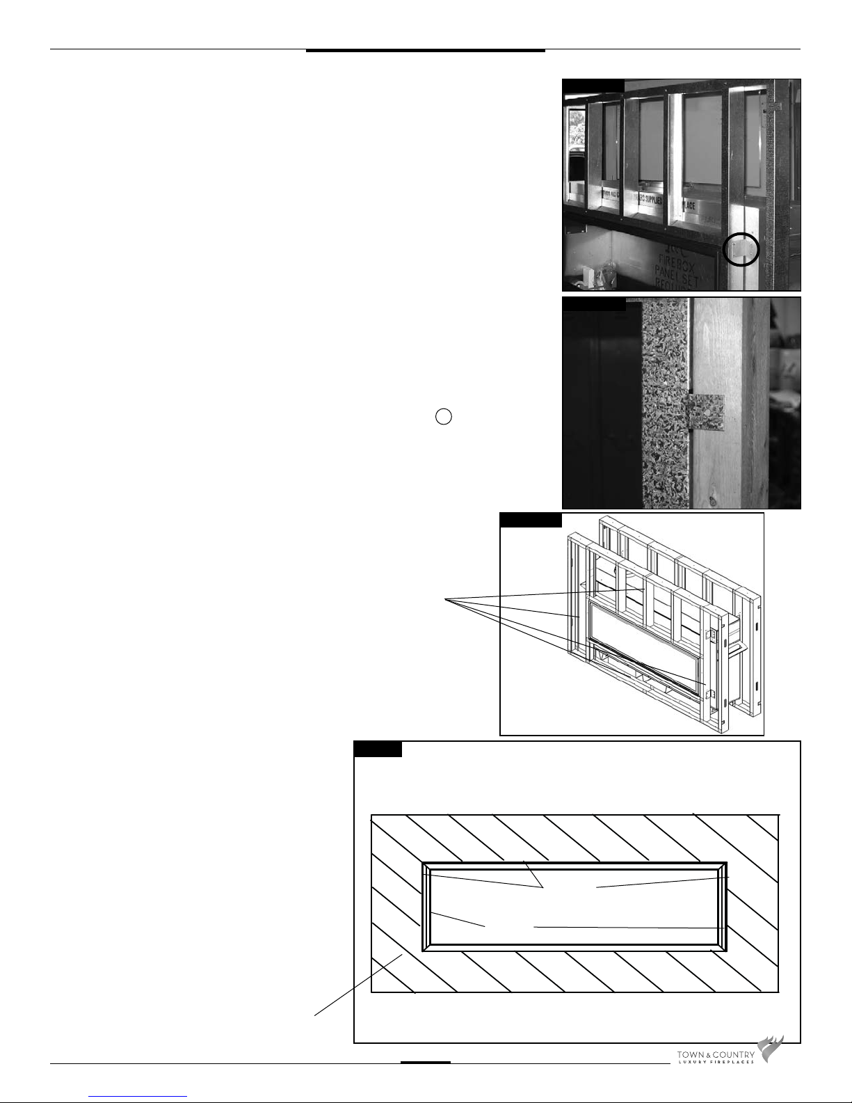
This replace may be recessed up to a
maximum depth of 6”, this recess must
be constructed from non combustible
material. The space between the
outside lintels and the rebox must be
completely free of any obstructions or
debris and the window with trim tted
must be able to move freely. No building material is permitted to protrude
past the lintel bars attached to the replace under ANY circumstance.
• Use drywall screws to install
the non-combustible board. The
non-combustible board should cover
the total area of the steel stud framing
kit, as a minimum, but can be extended
if desired. (Fig. #15)
8
Fig. #15
NON COMBUSTIBLE
BOARD
Fig. #15b
GLASS
FRAME
FRAMING
EDGES
NON COMBUSTIBLE
FINISH MATERIAL
TCWS.54CSTE 110712-72
13

Adjustable Lintel
1. The adjustable lintel assembly has two
orientations for desired nishing. The anged
edge and the hemmed edge. The lintel
comes factory installed with the ange edge
out . If the desired edge is different from the
factory setting, use the following steps to
change it(Fig.#16).
2. Remove the window trim from the window
frame (Fig.#17).
3. Pull the lintel assembly away from the replace to disengage from the lintel support
brackets.
4. Rotate the assembly to have the desired
edge away from the replace then align and
re-engage on the lintel support brackets .
5. Remove the front bottom lintel screw located
on the bottom outside corners of the lintel
assembly and move it to the hole on the
other side of the center bottom lintel screw.
(Fig. #19).
NOTE: The lintel assembly has a maximum
range of adjustability of 5/8” to accommodate varying facing material thicknesses.
The maximum depth of facing material is
6” (Fig.#15b).
Fig. #16
HEMMED EDGE
FLANGED EDGE
Fig. #17
TRIM
Fig. #18
6. Slide the lintel in or out to desired position
within the maximum adjustable range.
7. Tighten the lintel clamping screws and the
bottom lintel screws. (Fig.#18).
8. Re-attach the window trim.
Fig. #19
LINTEL
CLAMPING
SCREW
FRONT BOTTOM
LINTEL SCREW
CENTER
BOTTOM
LINTEL SCREW
TCWS.54CSTE 110712-72
14
Maestro Control
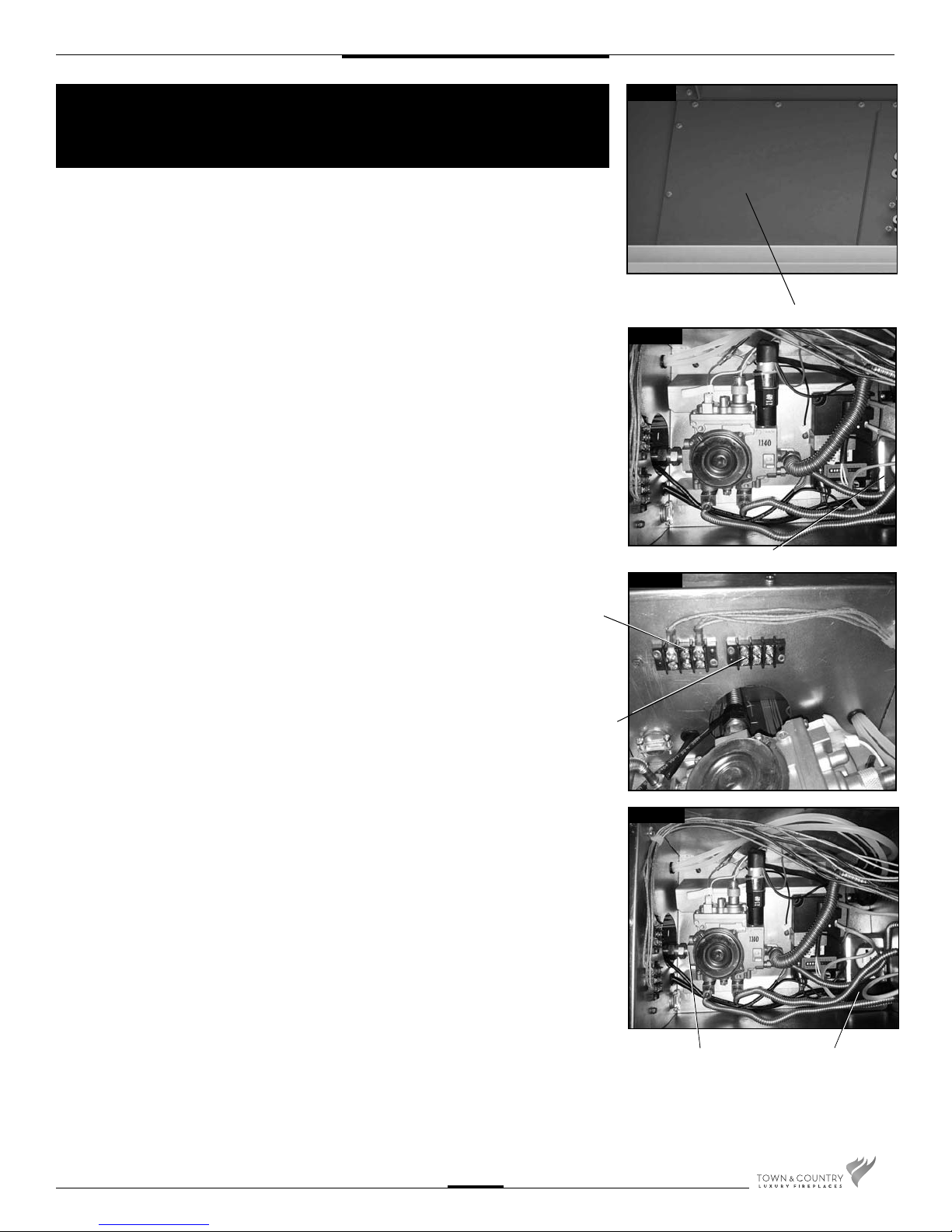
Plumbing and Electrical
The gas control system is located beneath the replace, below an access panel in the rebox
bottom and the secondary oor (if installed). The replace is operated via a wall switch and
a hand held remote control unit.
The wall control is connected to the replace by a 25 ft. communication cable supplied with the
replace. The communication cable can be extended with an optional 25 ft. extension kit.
Fig. #16
Installation
1. Place the replace in the desired location.
2. Remove the window from the replace.
3. Remove access panel from ue side of the rebox bottom(Fig. #16).
4. Connect a 110 V. AC electrical supply to the outlet installed inside the control box
(Fig. #17).
5. Connect a 110 V. AC switched electrical supply to the electrical blocks installed inside
the control box for the lighting. Block A is for the upper lights installed in all units. Block
B is for the lighting in the secondary oor that comes with the optional black diamond
burner kit. (Fig. #18)
6. Connect the gas supply to the valve (Fig. #19).
7. Plug the A/C adaptor into the outlet (Fig. #19).
BLOCK “A”
BLOCK “B”
ACCESS PANEL
Fig. #17
ELECTRICAL OUTLET BOX
Fig. #18
8. Attach the electrical box for the supplied wall control to the framing in the desired
location (up to 50 ft. away). (25 ft. is supplied with replace. An additional 25 ft. can
be achieved by using the optional kit (Part # 5005.064) available from your
dealer).
TCWS.54CSTE 110712-72
15
Fig. #19
GAS CONNECTION
A/C ADAPTER
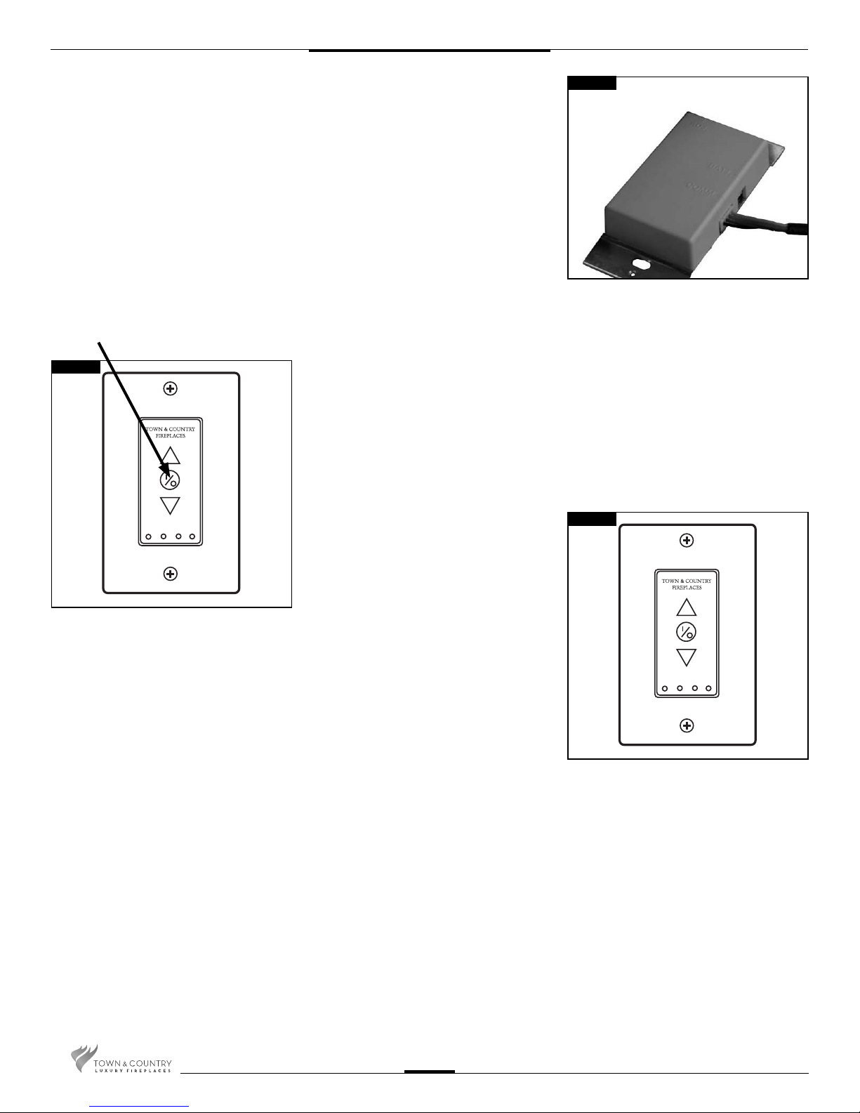
9. Route the communication cable as required to the wall control electrical box.
10. Attach the communication cable to the wall control. (Fig. #20)
11. Fasten the wall switch to the electrical box.
12. Fasten the faceplate to switch
13. If not already installed, install the burner and media set using the instructions supplied
with the burner kit.
14. Turn on the gas supply and check that all connections are tight and leak free.
15. Turn on gas and electrical supplies.
16. Press the center button on the wall control (Fig. #22). The igniter will start to spark.
After a short time the pilot will light, followed by the main burner.
Fig. #20
Fig. #22
17. Press the up button on the wall control
and hold it for 5 seconds or until a clicking
sound is heard from the gas control (Fig.
#23). Release the button, check manifold
pressure and ensure that it’s correct.
(Refer to Burner installation manual)
18. Press the center button of the wall control.
The replace will shut off.
19. Install the remaining screws in the access
panel and tighten.
20. Remove the pressure gauge and the
extension test tting and thread the
pressure test port plug into the pressure
test port. Thread sealant is required on
the threads. (Refer to Burner installation
section in this manual)
21. Turn the replace on and verify that
the connections are tight.
Fig. #23
TCWS.54CSTE 110712-72
16
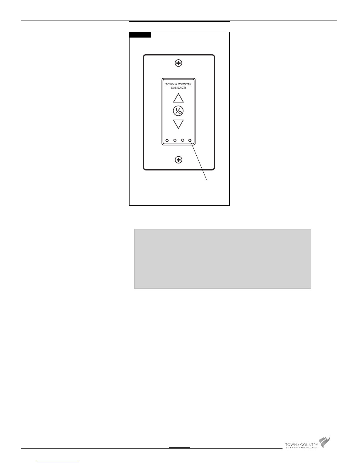
Pre-Purge Mode
The TCWS.54CSTE is for use with a
power vent only.
Follow these instructions to activate the
power vent pre-purge feature. This feature
must be activated for the safe operation of
this appliance.
Switching to the power vent pre-purge
mode:
1. To turn feature ON and OFF, press and
hold the STANDING PILOT button on the
wallswitch for 10 seconds (Fig.#24).
2. When the feature is activated, the green
LED should ash (0.5 seconds ON, 0.5
seconds OFF) 5 times.
3. When the feature is deactivated, the red
LED should ash (0.5 seconds ON, 0.5
seconds OFF) 5 times.
4. When the pre-purge feature is ON:
Fig. #24
STANDING
PILOT BUTTON
• The low battery backup warning feature
will be disabled and the LED will not
ash to indicate low battery (The battery
backup must be removed when using a
power vent).
• The Standing Pilot feature will be de-
activated (feature not available when
Power Vent Pre-Purge Mode is active).
• Upon receiving any ON command, the
power vent output will close immediately,
but the ignition cycle will NOT begin for 10
seconds (pre-purge). This means that
the module WILL NOT emit a spark and
WILL NOT energize the pilot operator
and the 60 second ignition trial period
WILL NOT begin until the 10 second
pre-purge delay is complete.
• Upon receiving any ON command, the
green LED will ash (0.5 seconds ON,
0.5 seconds OFF) for 10 seconds so
the user will know that the replace is
operating.
NOTE:
The pre-purge feature must be
activated for the safe operation of
this appliance.
TCWS.54CSTE 110712-72
17

Gas Supply
Servicing of the appliance can be performed from inside the unit and through the access
panel located in the rebox bottom.
Caution: The gas line should be installed by a quali ed service person in accordance with
all building codes. This section is intended as a guide for quali ed technicians installing this
appliance. Consult local and/or national building codes before proceeding.
• Gas supply line access holes are located beneath the replace on the ue side of the
Control Box. Gas valve inlet accepts a 3/8" N.P.T. tting. Correct gas line diameter must
be used to assure proper operation and pressure.
• The replace has an input rate of 61,000 BTU/HR on both Natural Gas and
Propane.
• A drip leg must be installed in the gas supply line going to the gas control
valve to minimize the possibility of any loose scale or dirt within the gas
supply line from entering the control valve.
• It is essential that a union or anged connection be installed just upstream of the
valve and inside the control compartment to allow for repair or replacement of the
gas valve.
Check local codes for additional requirements.
1. Connect the gas supply to the valve (Fig. #24a).
Fig. #24a
GAS VALVE INLET
2. Turn on the gas supply and check that all connections are tight and leak free.
WARNING: The access panel including gasket must be
reinstalled after conversion/installation or servicing
has been completed. Failure to do so will cause
overheating and premature failure of the control system.
Gas Pressure Check
Note: To test the gas pressure, turn off the gas supply before removing the plug from
the supply pressure test port or manifold pressure test port.
Verify gas pressures with the replace lit and on the highest setting.
Please refer to page 51 for gas pressure testing procedure.
Correct gas pressure requirement:
Supply Pressure Natural Gas Propane BTU
Min. Pressure 5.0" WC 12.5" WC
(For purpose of input adjustment)
Max. Pressure 13.9" WC 13.9" WC
Manifold Pressure
Maximum 3.5" WC 11" WC 61,000 (17.8kw)
Minimum 2.1" WC 5.5" WC 39,000 (11.5kw)
115VAC 60Hz 8.5A
TCWS.54CSTE 110712-72
18

Venting
NOTE: This replace uses Power Vent only (TCVT.PVOB2, TCVT.PVOFM or TCVT.
PVOFM3).
Various combinations of vent runs may be used. For optimum performance and ame
appearance, keep the vent length to a minimum and limit the number of elbows. Connections
between each vent system component must be tightly joined, secured with sheet metal
screws and sealed with high temperature self adhesive tape.
VENT SUPPORTS: A minimum of 1 support every 4’ must be used.
CAUTION: UNDER NO CONDITION SHOULD COMBUSTIBLE MATERIAL BE CLOSER
THAN 1 3/4 INCHES FROM ANY PART OF THE VENT PIPE.
Venting Components
SIMPSON DURAVENT COMPONENTS
Number Description
1208 6” Pipe Length
1207 9” Pipe Length
1206 12” Pipe Length
1204 24” Pipe Length
1203 36” Pipe Length
1202 48” Pipe Length
1211 11” to 14-5/8” Pipe, Adjustable
1217 4-10” Pipe, Adjustable
1245 45° Elbow
1290 90° Elbow
1240 Round Ceiling Support /Wall Thimble Cover
1241 Cathedral Ceiling Support Box
1242 Wall Firestop
1247 Wall Thimble
1263 Ceiling Firestop
1288 Wall Strap
SELKIRK DIRECT-TEMP
Number Description
1605006 6” Pipe Length
1605009 9” Pipe Length
1605012 12” Pipe Length
1605018 18” Pipe Length
1605024 24” Pipe Length
1605036 36” Pipe Length
1605048 48” Pipe Length
1605082 4-10” Pipe, Adjustable
1605215 45° Elbow
1605230 90° Elbow
1605424B Cathedral ceiling support box (blk)
1605500 Firestop spacer
1605460B Wall thimble (blk)
1605430 Wall support band
SECURE VENT COMPONENTS
Number Description
SV5L6 6” Pipe Length
SV5L12 12” Pipe Length
SV5L24 24” Pipe Length
SV5L36 36” Pipe Length
SV5L48 48” Pipe Length
SV5LA 6” Pipe, Adjustable
SV5LA12 12” Pipe, Adjustable
SV5LA24 24” Pipe, Adjustable
SV5E45 Swivel 45° Elbow
SV5E90 Swivel 90° Elbow
SV5CSB Adjustable decorative sq. cathedral support
SV5AC Collar for decorative sq. cathedral support
SV5SU Universal support
SV5SD Floor support
SV5BM Wall band
SV5RSA Attic radiation shield
SV5RSM Wall radiation shield
SV5BF Firestop
ICC MODEL EXCELDIRECT
Number Description
TC-5DL6 6” Pipe Length
TC-5DL1 12” Pipe Length
TC-5DL2 24” Pipe Length
TC-5DL4 48” Pipe Length
TC-5DLF 36” Flexible Length
TC-5DLT 12” Pipe, Adjustable, Galvalume
TE-5DE45 Swivel 45° Elbow, Galvalume
TE-5DE90 Swivel 90° Elbow, Galvalume
TM-5SS Square Support / Radiation Shield
TM-5RDS Round Support / Radiation Shield
TM-5CS Ceiling Support / Firestop
TM-OS Offset Support
TM-SR Roof Support
TM-WS Adjustable Wall Support
TM-5WT Insulated Wall Thimble
TM-5TR Trim Ring, Black
TM-5AS Attic Radiation Shield / Firestop
TCWS.54CSTE 110712-72
19
PAINT:
TCVT.PVOFM Power Vent Installation
The vent terminal comes pre-painted
with Thurmalox 230 Series paint by
Dampney Co., but can be painted
to match your wall nish color
using high temperature paint that
can withstand temperatures of at
least 250 degrees Fahrenheit or 120
degrees Celcius.
Ensure the your paint is compatible
with Thurmalox 230 Series paint.
MINIMUM CLEARANCES TO
COMBUSTIBLE
Terminal casing:
0in. (0mm)
Vertical vent pipe:
1.75 in. (38mm)
Horizontal vent pipe:
1.75 in. (38mm)
All other clearances are as per the replace
installation instructions.
Locate the replace as per the main instructions supplied.
Make the following modi cations to add the components used with the Flush
Mount Power Vent Kits. This Kit can only be used in conjunction with the “C” series
versions of Town and Country replaces, except the TC54.CE. This installation must
conform with local codes or, in the absence of local codes, with the National Fuel
Gas Code, ANSI Z223.1/NFPA 54, or the Natural Gas and Propane Installation Code,
CSA B149.1.
All electrical installations should be performed by a quali ed electrician to the
Canadian and U.S. National Electrical Codes (CSA C22.1 for Canada), (ANSI/NFPA
70 for the U.S.) and/or local electrical codes.
UNDER NO CIRCUMSTANCES SHALL A RHEOSTAT BE USED
TO ALTER THE VOLTAGE SUPPLY TO THIS UNIT.
Contents of Power Vent Kit
ITEM PART No. DESCRIPTION QTY
1 TCVT.8018 Flush Mount Power Vent Assy. 1
2 8020 Inner wall plate 1
3 8029 Wall Pipe cover 1
4 TCVT.8028WLD Wall Sleeve Assembly 1
Fig. #26
VENTING CONFIGURATIONS
Maximum total vent length
is 110ft plus six 90-degree
elbows or combination of other
elbows equaling 90-degrees,
with a maximum 66 foot
vertical rise.
Minimum total vent length is
one 90-degree elbow plus one
foot horizontal.
The vent can be installed with
any combination of rise and
run including up to 3 ft below
the unit. Ensure vent pipe is
properly supported.
Maximum Combined
vertical & horizontal
venting 110 ft plus six
90-degree elbows.
Venting Con gurations
Min. 1 3/4” Clearance to
combustible surfaces from
vent pipe.
Min. venting - one
90-degree elbow plus
one foot horizontal.
66’ MAX. VERTICAL
3 ft. below unit (Max) to
center of vent pipe
TCWS.54CSTE 110712-72
20
Minimum Vent Length Chart
Fig. #27
B
TCWS.54CSTE
A B
Minimum Pipe
Rise Length
47” 1 foot
A
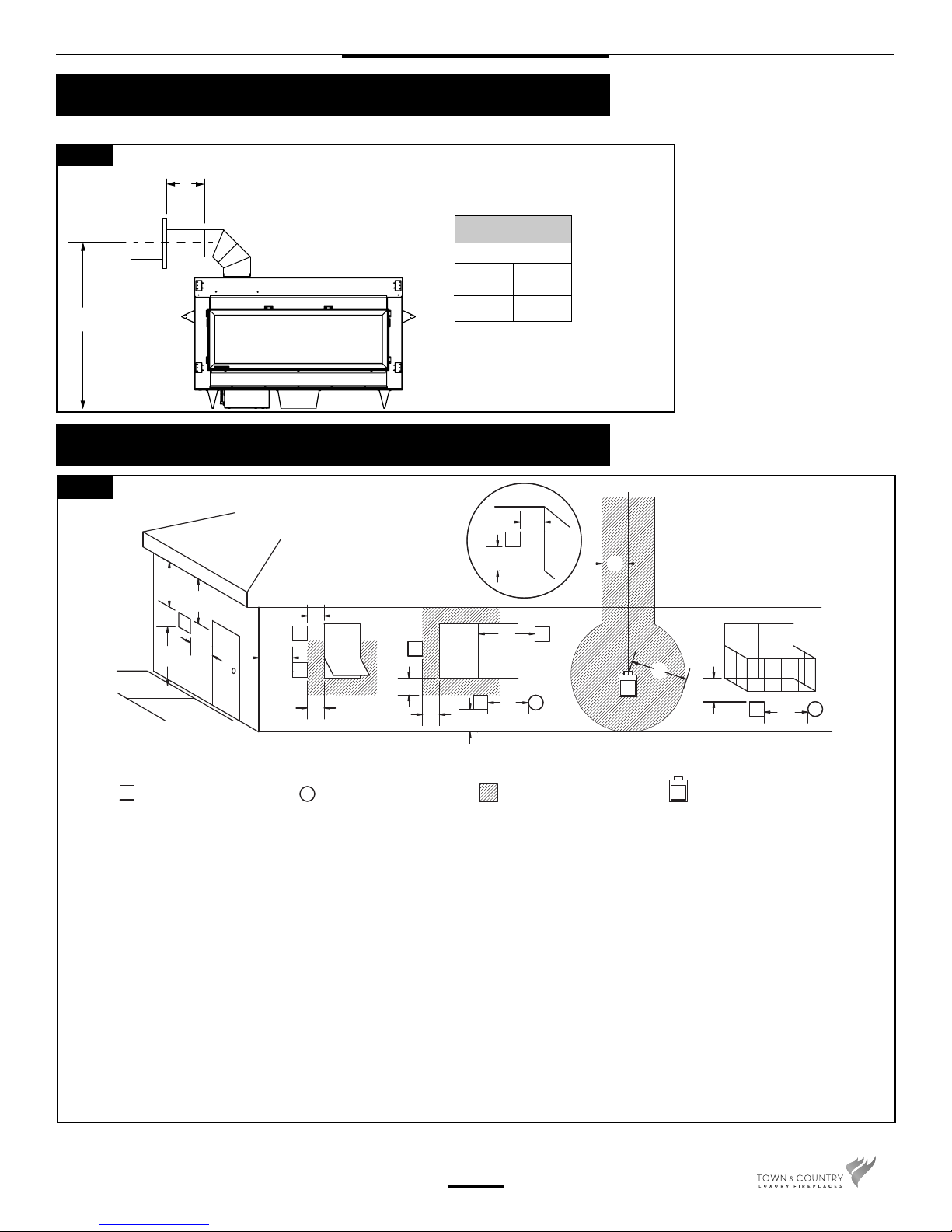
Vent Terminal Minimum Clearances
Fig. #28
INSIDE
CORNER
DETAIL
D
E
V
B
L
VENT TERMINAL GAS METER
V
C
FIXED
V
CLOSED
F
OPEN ABLE
V
B
AIR SUPPLY INLET
A
OPEN-
V
ABLE
B
B
V
A
A= clearances above grade, veranda, porch, deck, or balcony [*
12 inches (30 cm) minimum]
B= clearance to window or door that may be opened [* 12
inches (30 cm) minimum]
C= clearance to permanently closed window [minimum 12
inches (30 cm) recommended to prevent condensation on
window]
D= vertical clearance to ventilated soffit located above the ter-
minal within a horizontal distance of 2 feet (60 cm) from the
edge of the terminal [0 inches (0 cm) minimum]
E= clearance to unventilated soffit [0 inches (0 cm) minimum]
F= clearance to outside corner [6 inches (15 cm) minimum]
G= clearance to inside corner [3 inches (7.5 cm) minimum]
G
V
A
V
B
FIXED
CLOSED
A
J
AREA WHERE TERMINAL
IS NOT PERMITTED
H
I
G
M
V
K
G
H= * not to be installed above a meter/regulator assembly within
3 feet (90 cm) horizontally from the center-line of the regulator
I= clearance to service regulator vent outlet [* 6 feet (1.8 m)
minimum]
J= clearance to nonmechanical air supply inlet to building or the
combustion air inlet to any other appliance [* 12 inches (30
cm) minimum]
K= clearance to a mechanical air supply inlet [* 6 feet (1.8 m)
minimum]
L= ^ clearance above paved side-walk or a paved driveway
located on public property [* 7 feet (2.1 m) minimum]
M= clearance under veranda, porch, deck, or balcony
A
[0 inches (0 cm) minimum**]
^ a vent shall not terminate directly above a side-walk or paved driveway which is located between two single family dwellings and
serves both dwellings*
** only permitted if veranda, porch, deck, or balcony is fully open on a minimum of 2 sides beneath the oor*
* as speci ed in CGA B149 Installation Codes, Note: local Codes or Regulation may require different clearances
* for U.S.A. Installations follow the current National Fuel Gas Code, ANSI Z223.1
TCWS.54CSTE 110712-72
21
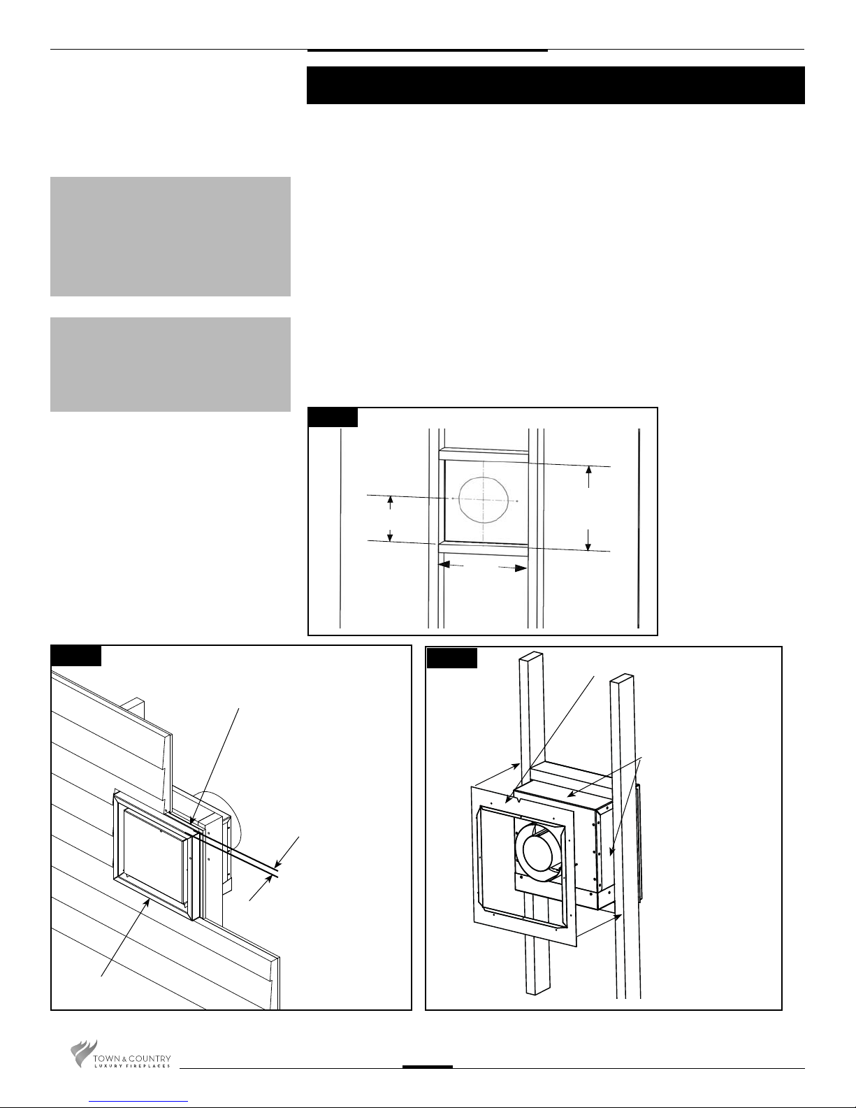
CAUTION:
This terminal is designed to be
nished ush to the nished outside
wall; under no circumstances
should this terminal be recessed
into the wall past this point.
(Fig. #30)
CAUTION:
The rise and run combination and the
number of elbows must not exceed
speci cations in Fig #26.
Horizontal (Side Wall) Venting
This kit uses either Simpson Duravent GS direct vent pipe, Secure Vent
direct vent pipe, Selkirk Direct-temp vent pipe or ICC Exceldirect vent pipe
with a 5” inner pipe and an 8” outer pipe. For part numbers see the table of
venting components on page 19 of this manual. This vent can only be used
as a side wall termination.
1. Locate the power vent termination following the clearance to combustible table(Page 20
& Page 21), venting con guration diagram (Fig. #26 & 27), and terminal location diagram
(Fig. #28).
2. Cut and frame a 14 1/2” wide by 14 3/4” high opening. For standard up and out
installations, the opening should be 3/4” lower than the minimum speci ed in Fig. #27.
Height of the opening will vary with each installation.
3. Attach the power vent terminal, by securing the outer anges on the perimeter of the
terminal to the outside wall; ensure that the terminal is the right way up (exhaust at the
bottom). Once secured to the building, the outer anges may be covered with siding/
stucco etc. up to the level of the perimeter edge. As per local building codes. See Fig. #30.
4. For wall thicknesses 7 1/2” or less, install the inner wall plate supplied over the terminal
as shown in Fig#31 and secure to the framing. See Fig. #31.
Fig. #29
Fig. #30
TERMINAL SECURING
FLANGE
WALL FINISH NO
DEEPER THAN 1 1/2”
9”
14 1/2”
Fig. #31
14 3/4”
INNER WALL PLATE
SEAL WITH SILICONE
ON ALL FOUR SIDES
EXHAUST
TCWS.54CSTE 110712-72
22
 Loading...