

Town & Country Fireplaces TCWS.54NGST04D Installation Instructions Manual

INSTALLER: Leave this manual with the appliance.
CONSUMER: Retain this manual for future reference.
These instructions are supplementary to the Installation
and Operating Instructions supplied with the replace
and should be kept together. Refer to the Installation
and Operating Instructions for proper gas supply, safety
requirements and operating instructions.
TCWS.54DST
TRANQUILITY
BURNER KIT
INSTRUCTIONS
150115-16 TCWS.54NGST04D 5056.425183D
PART# TCWS.54NGST04D
For TCWS.54DST
Series D
Fireplaces
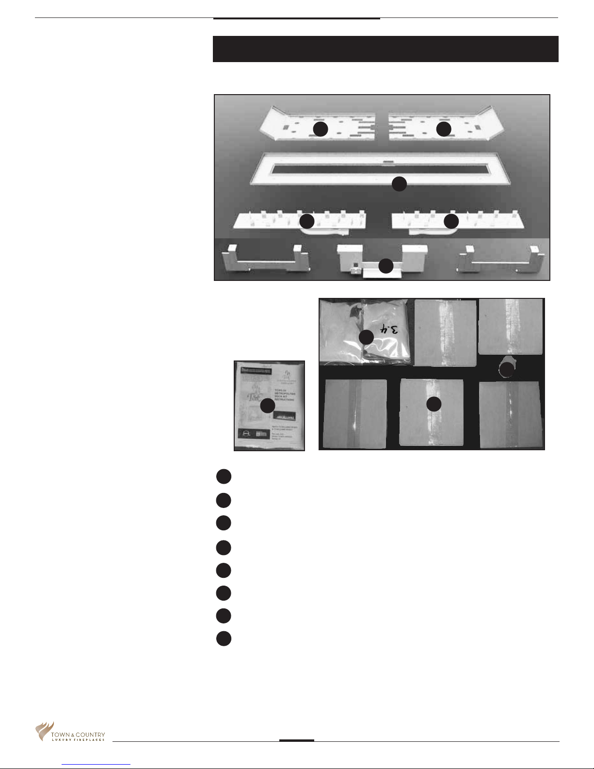
Contents of Package
GG
E
A
B
D
B
2 3.4 LBS SAND
1 HARDWARE PACK
D
H
A
C
F
C
D
E
F
G
H
1 PILOT ROCK
2 BURNER ASSEMBLIES
1 BURNER TRAY ASSEMBLY
5 PEBBLE SETS
2 SECONDARY FLOOR HALVES
WITHOUT LIGHTS
3 TRAY LEGS
TCWS.54NGST04D_150115-16
2
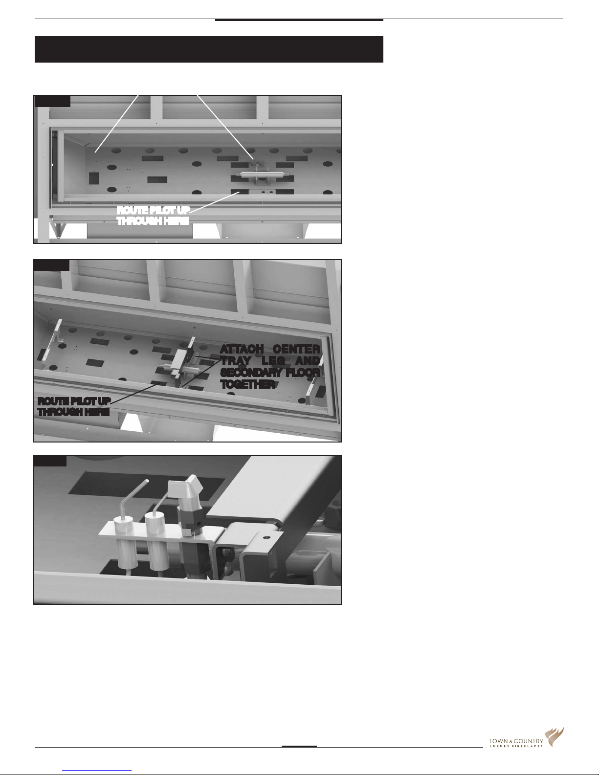
Tranquility Burner Installation
ATTACH HERE AND ON OPPOSITE SIDE
Fig #1
ROUTE PILOT UP
THROUGH HERE
Fig #2
ATTACH CENTER
TRAY LEG AND
SECONDARY FLOOR
TOGETHER
If converting to propane see
conversion instructions on page #8
before proceeding.
1. Install one side of the secondary
oor as shown. Repeat with the other
side but do not put in the two center
screws until you put the center tray leg
in place.
(Fig. #1 & Fig. #2)
2. Attach tray legs as shown in Fig. #2.
The center tray leg and the right side
of the secondary oor are attached
with the same screws to the center
oor leg.
ROUTE PILOT UP
THROUGH HERE
Fig #3
3. Attach pilot to center tray leg. (Fig. #3)
TCWS.54NGST04D_150115-16
3

NOTE: check air shutter for correct
fuel setting before proceeding
further. Both burners are the same.
Fully closed for natural gas.
13/64 (0.2)” open for LP.
4. Install burners as shown in Fig. #4.
Be sure to engage the venturis onto
the orices in the manifold and
rest burners together on the center
tray leg.
Fig #4
TIP: a light will aid aligning the holes in
the tray with the leg
CAUTION: The burners should be tightly
butted up against each other at the center
to ensure correct operation.
5. Remove the panel retainer clips from
inside the rebox and install the side
panels. Replace the panel retainer clips.
(Fig. #5 & #6)
ENGAGE BURNER VENTURIS
ONTO ORIFICES
Fig #5
Fig #6
TCWS.54NGST04D_150115-16
4
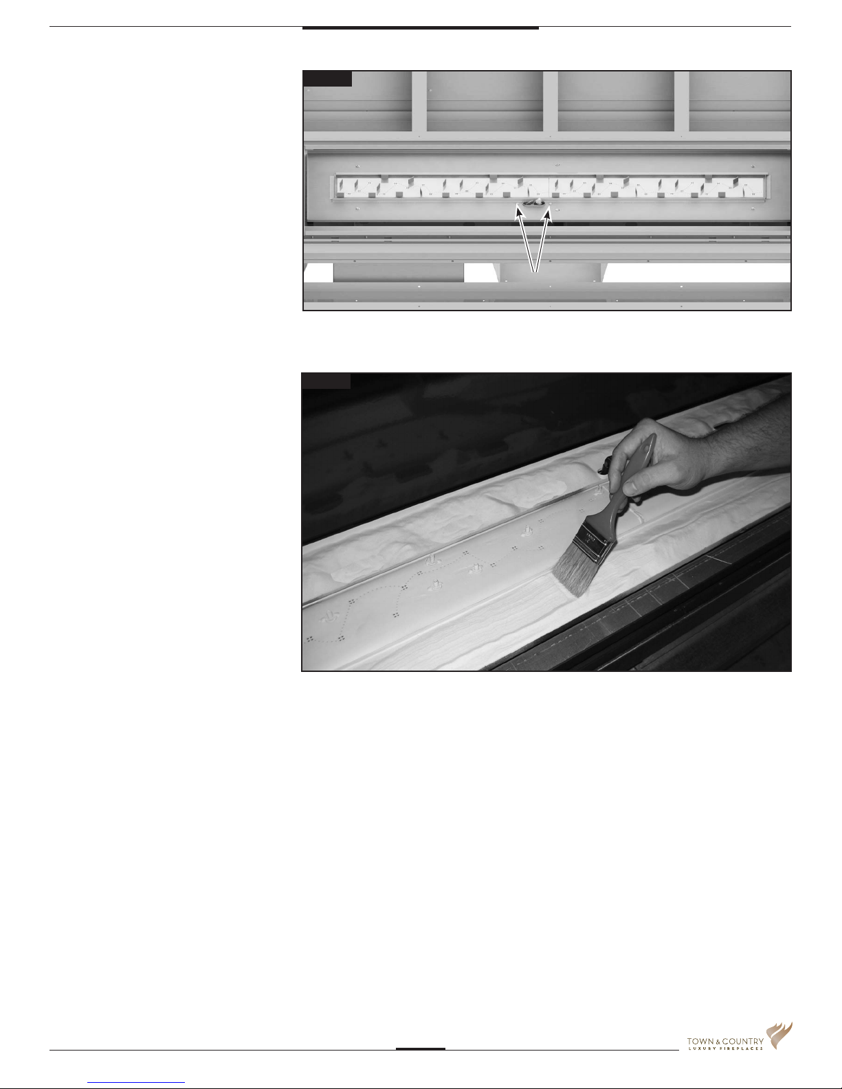
6. Install burner tray as shown in Fig. #7
using 8 screws. Secure tray around
pilot rst then the other 6 screws.
7. Place sand into the burner tray and
brush smooth. Use caution not to get
sand near the burner ports. (Fig. #8)
Fig #7
SECURE PILOT
HERE FIRST
Fig #8
TCWS.54NGST04D_150115-16
5
 Loading...