

Town & Country Fireplaces TCWS.54NGST03D Installation Instructions Manual

INSTALLER: Leave this manual with the appliance.
CONSUMER: Retain this manual for future reference.
These instructions are supplementary to the Installation
and Operating Instructions supplied with the replace
and should be kept together. Refer to the Installation
and Operating Instructions for proper gas supply, safety
requirements and operating instructions.
TCWS54
SEE THRU
DIAMOND BURNER
INSTALLATION KIT
INSTRUCTIONS
PART# TCWS.54NGST03D
210417-24 TCWS.54NGST03D 5056.425181D
Visit www.townandcountry.com for the most recent version of this manual
For TCWS54DST Series D
Fireplaces

Table of Contents
Contents of Package ........................................................................................................ 3
Diamond Burner Installation ............................................................................................. 4
Propane Conversion ....................................................................................................... 13
Conversion procedure ............................................................................................. 13
Gas Pressure Check ....................................................................................................... 16
Correct gas pressure requirement:.......................................................................... 16
Burner Flame Adjustment ............................................................................................... 17
Optional Long Beach Log Set Installation ...................................................................... 18
Log Placement ........................................................................................................ 18
Lights Wiring Diagram .................................................................................................... 22
Replacement Parts ......................................................................................................... 23
5056.425181D
2
TCWS.54NGST03D_210417-24
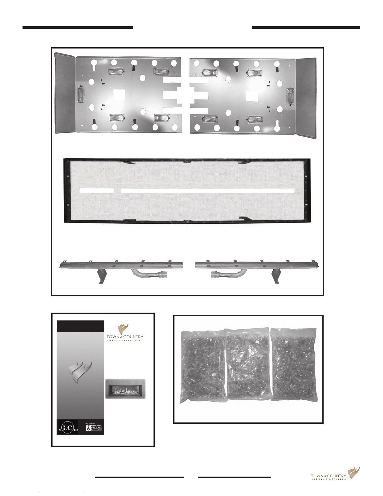
Contents of Package
Secondary oor panels
INSTALLER: Leave this manual with the appliance.
CONSUMER: Retain this manual for future reference.
These instructions are supplementary to the Installation
and Operating Instructions supplied with the replace
and should be kept together. Refer to the Installation
and Operating Instructions for proper gas supply, safety
requirements and operating instructions.
TCWS54
SEE THROUGH
DIAMOND BURNER
INSTALLATION KIT
INSTRUCTIONS
PART# TCWS.54NGST03D
For TCWS54DST Series D
Fireplaces
070417-16 TCWS.54NGST03D 5056.425181D
Visit www.townandcountry.net for the most recent version of this manual
Tray for glass media
Burners
3 x 5lb bags Diamond Glass Media
TCWS.54NGST03D_210417-24
3
5056.425181D
Diamond Burner Installation
If converting to propane see “Propane Conversion” on page 13 before proceeding.
NOTE: For purposes of clarity, the “Front” of the fireplace shall be the side which has
access to the electrical connection compartment cover, the connection to the gas valve and
the side which places the control compartment cover and the coaxial vent located on top of
the fireplace to your left.
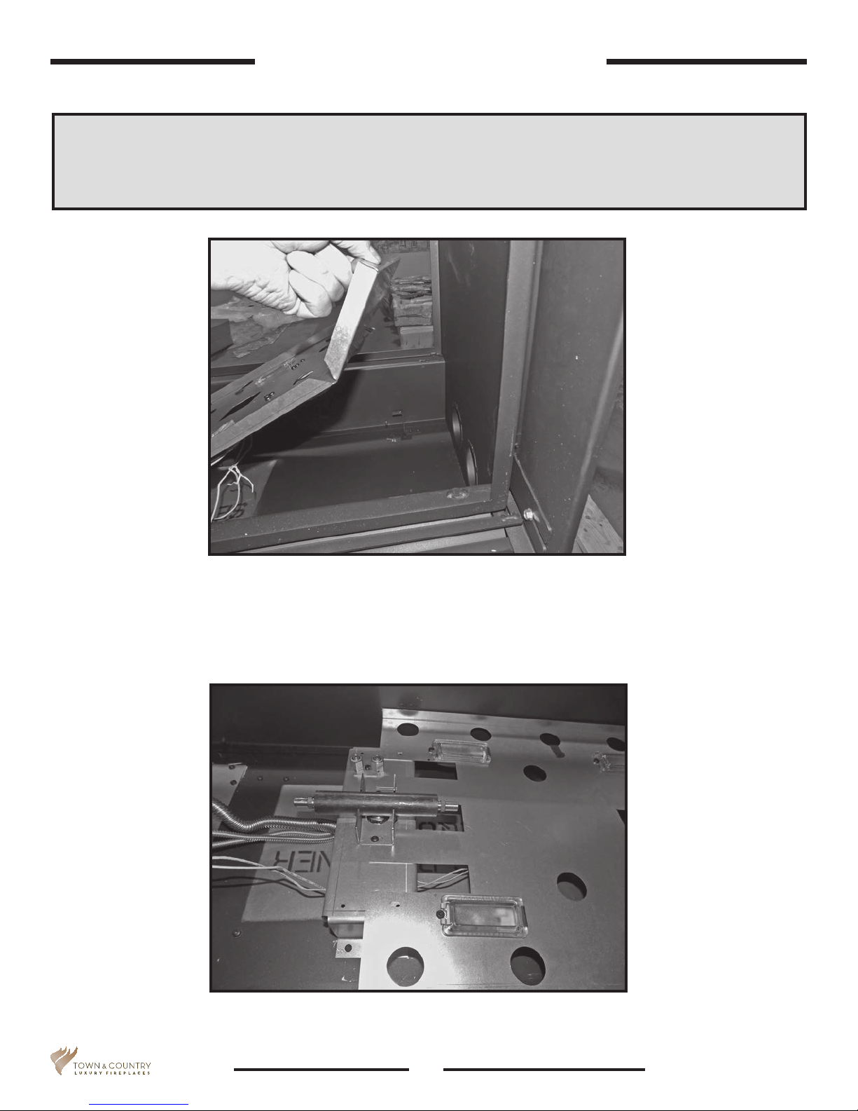
Figure 1: Inserting secondary oor panel into the right side.
1. With the control compartment to your left, place one of the two secondary oor panels in the right side
of the rebox (Figure 1) and route the two wires from the lights underneath the plate over to the left hand
side of the rebox (Figure 2).
Figure 2: Right hand panel in place with its wires brought out from
under it.
5056.425181D
4
TCWS.54NGST03D_210417-24
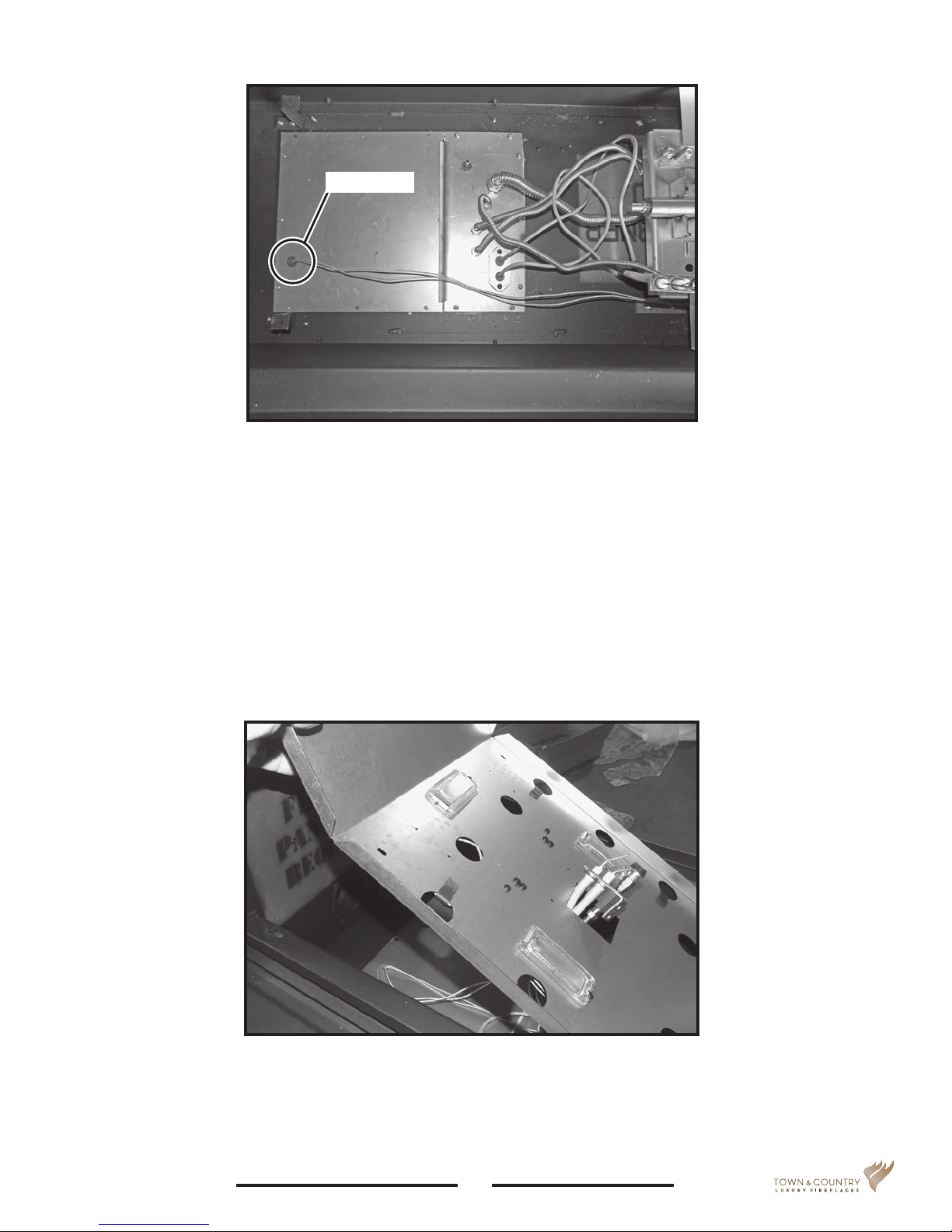
Grommet
Figure 3: Wires through grommet.
2. Feed the two wires from the right side secondary oor panel down through the left most grommet over the
gas control compartment cover (Figure 3).
3. Insert the other secondary oor panel into the left side of the rebox. As the panel is lowered, feed its two
lights wires into the same grommet as was done with the wires from the right hand oor panel. Also feed
the pilot assembly through the square opening in the panel (Figure 4).
Figure 4: Inserting secondary oor panel into the left side.
TCWS.54NGST03D_210417-24
5
5056.425181D
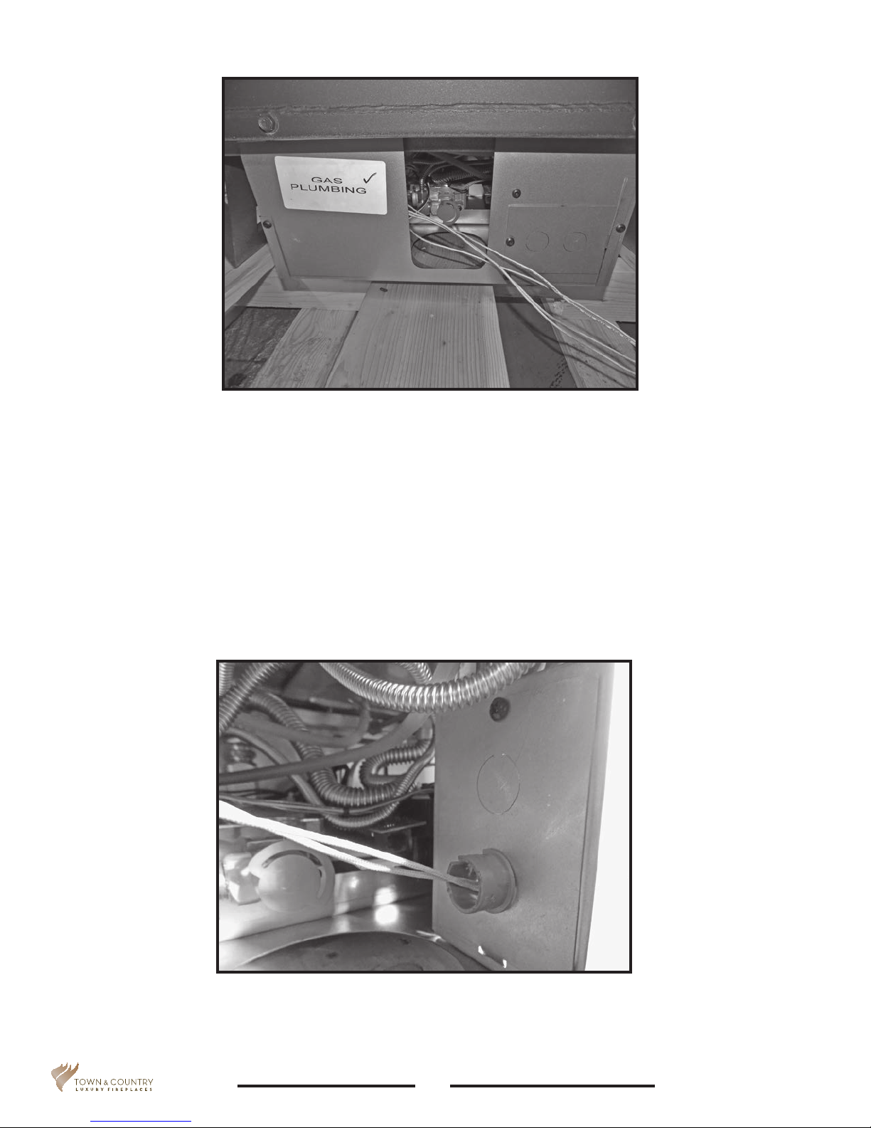
Figure 5: Lights wiring coming from grommet.
4. Guide the four light wires from the bottom of the gas control compartment out through the opening as
shown in Figure 5.
5. From inside the control compartment, punch out one of two available knockouts located in the electrical
connection compartment, install a plastic grommet (not included) to protect the wires and feed the wires
into the compartment. (Figure 6).
Figure 6: Threading wires through knockout.
5056.425181D
6
TCWS.54NGST03D_210417-24
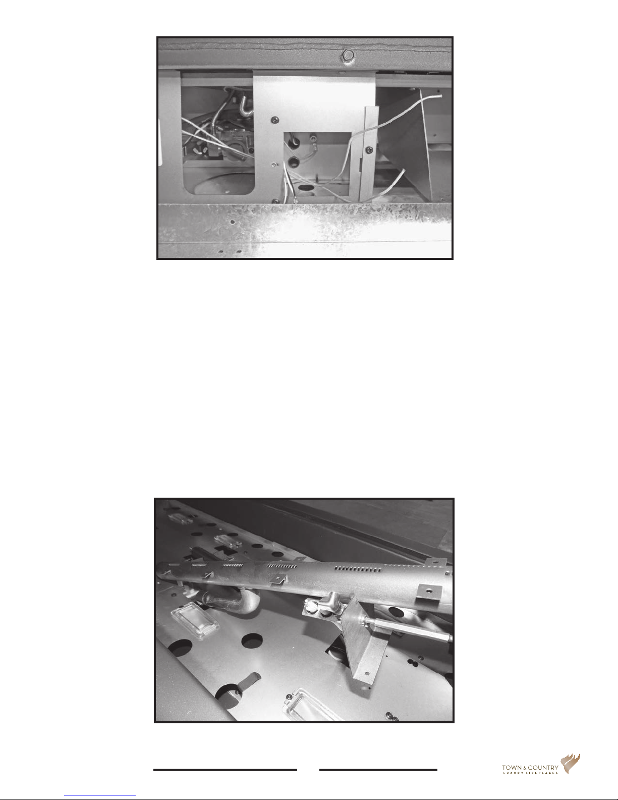
Figure 7: Bringing wires through front plate.
6. Remove the electrical connection compartment cover and feed all four lights wires through the opening.
The lights wiring will connect to the wiring that supplies the re place power (Figure 7).
7. Connect the wires to a switched 120 VAC, 60Hz, 3A power supply, one pair made up of one wire from the
left and one wire from the right light set to the “HOT” incoming line. The remaining pair to the “Neutral”
incoming line. See “Lights Wiring Diagram” on page 22. Reinstall the electrical connection compartment cover.
8. Return to the rebox and secure the two secondary oor panels with four T20 screws for each of the two
panels.
9. From the REAR of the replace, position one of the two burners on an angle and attach the pilot assembly
to the burner leg using two Robertson screws provided (Figure 8). Note that the pilot will be positioned on
an angle.
Figure 8: Attaching the pilot assembly to the burner leg.
TCWS.54NGST03D_210417-24
7
5056.425181D

Figure 9: Securing the burner leg to the secondary oor panel.
10. Slip the gas burner venturi over the orice and screw the burner leg to the secondary oor panel using a
T20 screw (Figure 9).
11. Place the second burner in the rebox so that its venturi ts over the second orice. Secure the leg to the
secondary oor panel.
NOTE: Check air shutter for correct fuel setting before proceeding further. Both burner shutters
are to be set the same. Fully closed for NATURAL GAS and 3/16” open for LIQUID PROPANE.
CAUTION: The burners should be tightly butted up against each other at the center to ensure
correct operation.
Figure 10: Shutter gap settings.
5056.425181D
3/16” Open for Propane Gas
Fully closed for Natural Gas
8
TCWS.54NGST03D_210417-24
 Loading...