

Town & Country Fireplaces TCWS.54NG04.C2 Instructions For The Use

INSTALLER: Leave this manual with the appliance.
CONSUMER: Retain this manual for future reference.
These instructions are supplementary to the Installation
and Operating Instructions supplied with the replace
and should be kept together. Refer to the Installation
and Operating Instructions for proper gas supply, safety
requirements and operating instructions.
TCWS.54NG04.C2
TRANQUILITY
BURNER KIT
INSTRUCTIONS
230911-16 5056.42521042 TCWS.54NG04.C2
PART# TCWS.54NG04.C2
For TCWS Series C
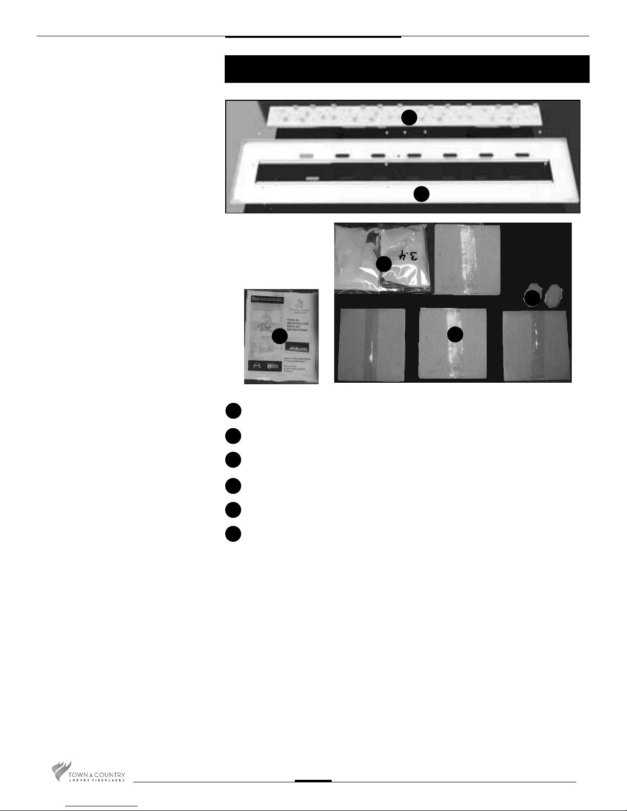
Contents of Package
D
A
E
C
A
B
C
D
E
F
B
2 3.4 LBS SAND
1 HARDWARE PACK
2 EQUALIZER ROCKS
2 BURNER ASSEMBLIES
1 BURNER TRAY ASSEMBLY
4 PEBBLE SETS
F
TCWS.54NG04.C2 230911-16
2
Tranquility Burner Installation
Fig #1
Fig #2a
If converting to propane see conversion instructions on page #7 before proceeding.
Install panels according to the TCWS.54CE
Installation and
Operating manual prior to burner installation.
(Page 23)
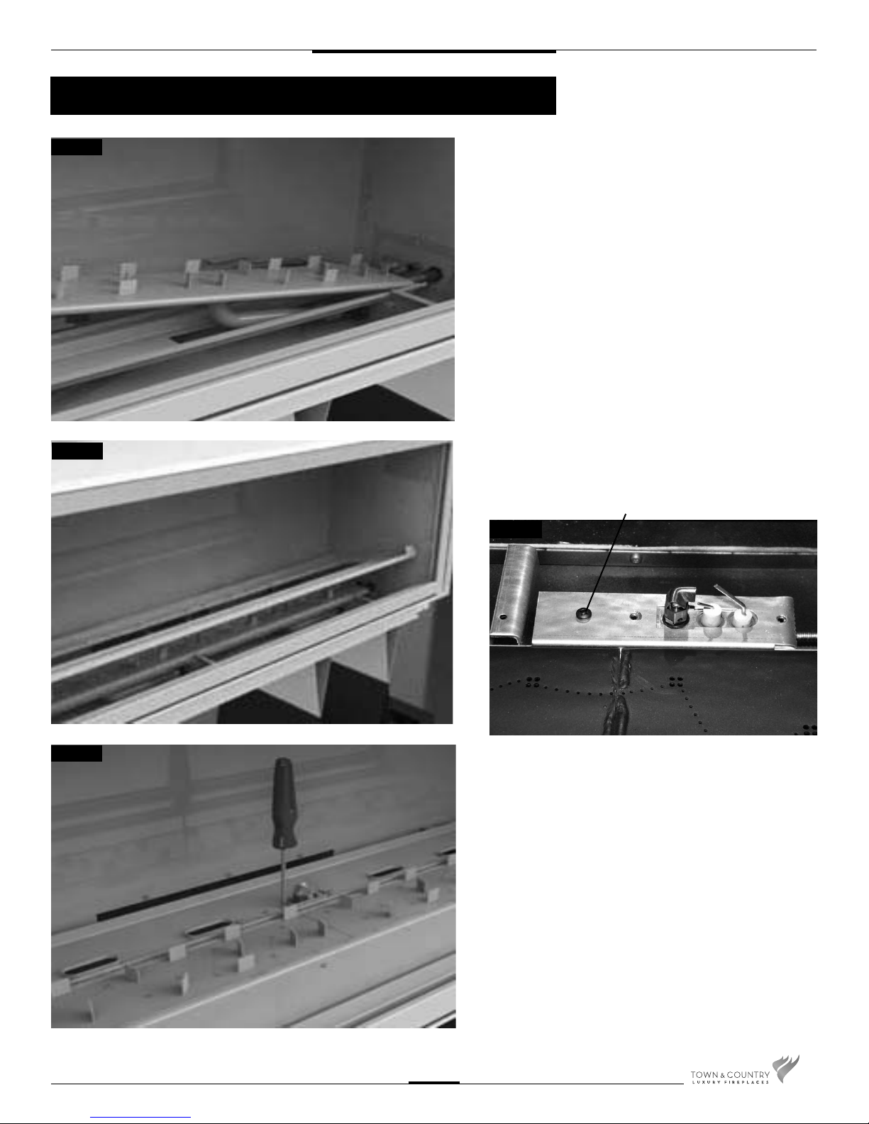
1. Install the right burner by tipping into location
trough and slipping the venturi tube over the ori ce.
Test for connection by lifting at a location pin on the
right side of the burner. Repeat with left burner.
(Fig. #1)
2. Tilt burner tray length-wise and insert into the
rebox. Be sure pilot is attached to burner support rail
with screw in rst hole position. (Fig. #2a & 2b)
FIRST HOLE POSITION
Fig #2b
Fig #3
TCWS.54NG04.C2 230911-16
3. Attach pilot to burner tray. (Fig. #3)
3
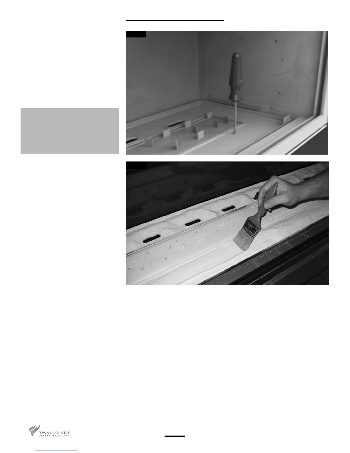
4. Secure the burner tray to legs using
eight screws (Fig. #4)
NOTE: a light will aid aligning the holes
in the tray with the leg
NOTE: check air shutter for correct
fuel setting before proceeding
further. Both burners are the same.
Fully closed for natural gas.
13/64 (0.2)” open for LP.
Fig #4
Fig #5
CAUTION: The burners should be tightly
butted up against each other at the center
to ensure correct operation.
5. Place sand into the burner tray and
brush smooth. Use caution not to get
sand near the burner ports. (Fig. #5)
TCWS.54NG04.C2 230911-16
4
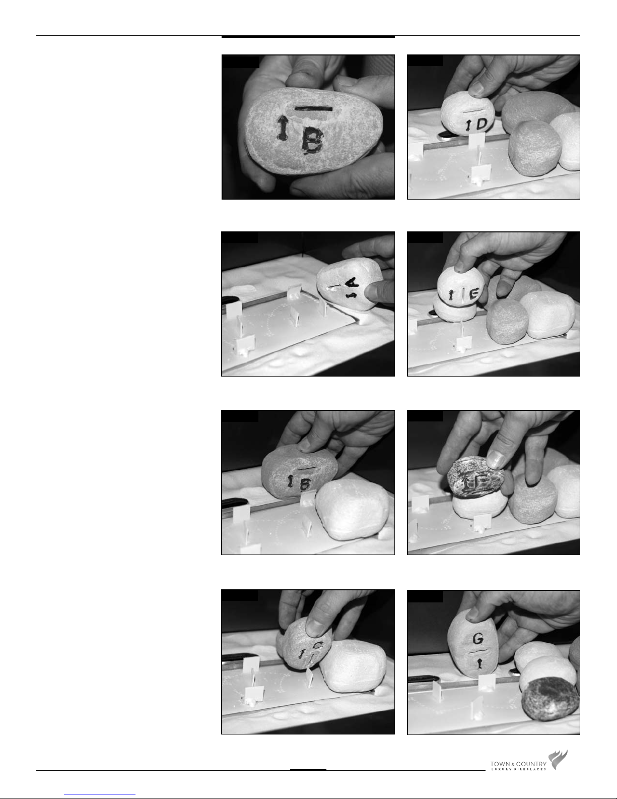
6. Each rock has a slot in it’s base and is
marked with a letter and an arrow.
(Fig. #6)
Fig #6
Fig #10
7. Place each rock as per the following
photographs, start from the right hand
side of the burner and ensure that the
arrow on each rock points towards the
front of the replace. (Fig. #7 to 15)
Fig #7
Fig #8
Fig #11
Fig #12
TCWS.54NG04.C2 230911-16
Fig #9
Fig #13
5
 Loading...