

Town & Country Fireplaces TCWS.54NG04.C Instructions Manual

IMPORTANT:
THESE INSTRUCTIONS ARE TO REMAIN
WITH THE HOMEOWNER
These instructions are supplementary to the Installation
and Operating Instructions supplied with the replace
and should be kept together. Refer to the Installation
and Operating Instructions for proper gas supply, safety
requirements and operating instructions.
TCWS.54NG04.C
TRANQUILITY
BURNER KIT
INSTRUCTIONS
040907-12 5056.4252104 TCWS.54NG04.C
PART# TCWS.54NG04.C
For TCWS Series C
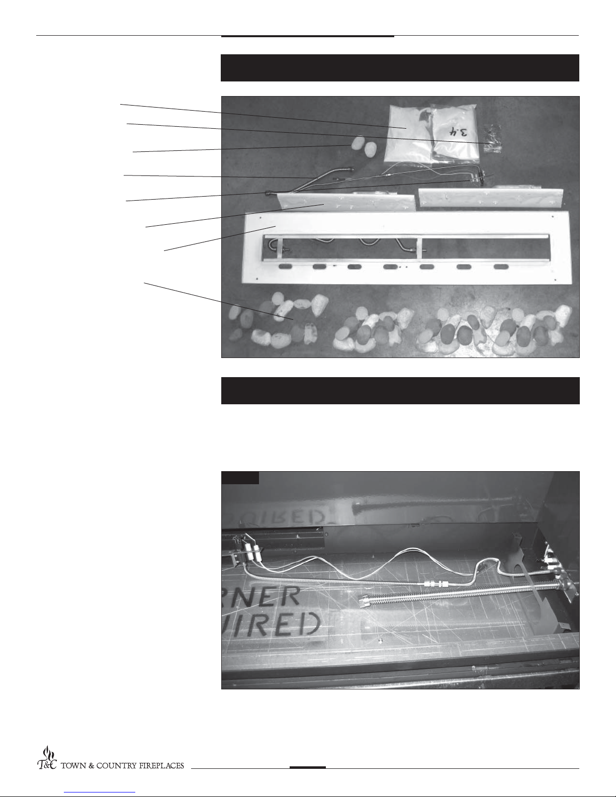
2 3.4 LBS SAND
1 HARDWARE PACK
2 EQUALIZER ROCKS
1 1/2 SS FLEX LINE
1 PILOT ASSEMBLY
2 BURNER ASSEMBLIES
1 BURNER TRAY ASSEMBLY
4 PEBBLE ASSEMBLIES
(Includes front and rear pebble
clusters and three top rocks)
Contents of Package
If converting to propane see
conversion instructions on page #6
before proceeding.
Install panels according to the
TCWS.54CE Installation and
Operating manual prior to burner
installation. (Page 23)
1 Attach fuel ex line and pilot assembly
to bulkhead ttings. (Fig. #1)
Tranquility Burner Installation
Fig #1
TCWS.54NG04.C 040907
2
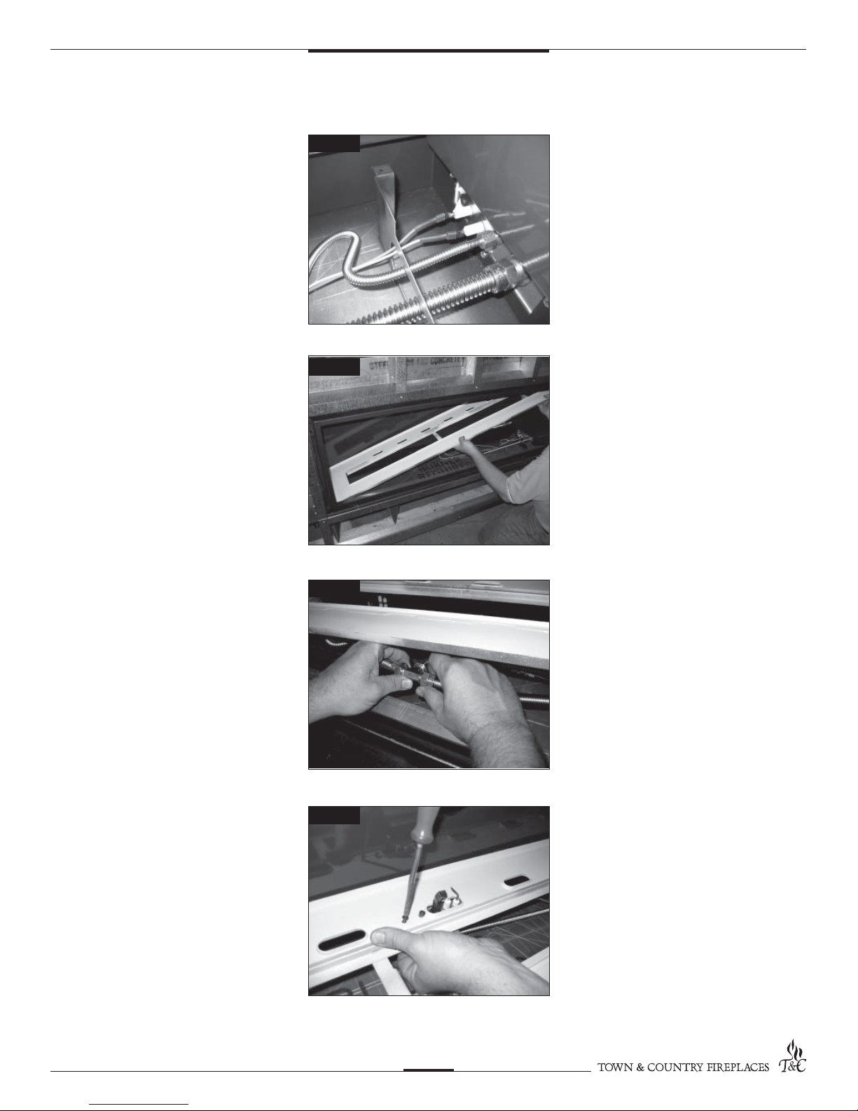
2. Connect spark electrode wire
(ORANGE) to the rear electrical bulk
head tting. Connect the ame sensor
wire to the front electrical bulk head
tting. (Fig. #2)
Fig #2
3. Tilt burner tray length-wise and insert
into the rebox. (Fig. #3)
4. While supporting one end of the
burner tray, connect gas line to the tee
on the underside of the burner tray.
(Fig. #4)
CAUTION:
Ensure that all connections are gas
tight.
Fig #3
Fig #4
5. Re-attach pilot to burner tray. (Fig. #5)
TCWS.54NG04.C 040907
Fig #5
3
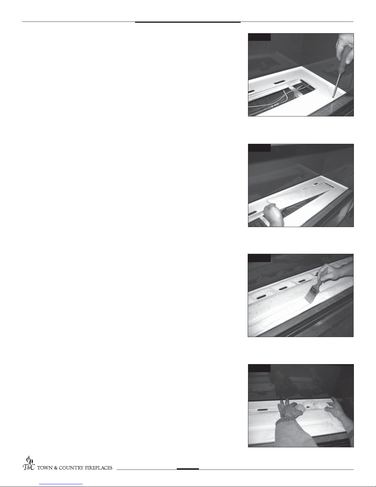
6. Secure the burner tray to legs using
four screws (Fig. #6)
NOTE:
A light will aid aligning the holes in
the tray with the leg
NOTE:
Check air shutter for correct fuel
setting before proceeding further.
Both burners are the same
Fig #6
7. Install the right burner by tipping into
location trough and slipping the
venturi tube over the ori ce. Test for
connection by lifting at a location pin
on the right side of the burner.
Repeat with left burner. (Fig. #7)
CAUTION:
The burners should be tightly
butted up against each other at the
center to ensure correct operation.
8. Place sand into the burner tray and
brush smooth. Use caution not to get
sand near the burner ports. (Fig. #8)
Fig #7
Fig #8
9. Place rear pebble cluster over the
burner. Use the pins on the burner
and holes in the pebble cluster to
locate the pebbles on the burner.
(Fig. #9)
NOTE:
Cluster may require a slight
adjustment to align pin holes.
4
Fig #9
TCWS.54NG04.C 040907
 Loading...