

Town & Country Fireplaces TCWS.54NG03C2 Instruction Manual

IMPORTANT:
THESE INSTRUCTIONS ARE TO REMAIN
WITH THE HOMEOWNER
These instructions are supplementary to the Installation
and Operating Instructions supplied with the replace
and should be kept together. Refer to the Installation
and Operating Instructions for proper gas supply, safety
requirements and operating instructions.
TCWS.54NG03C2
BLACK DIAMOND
BURNER KIT
INSTRUCTIONS
230911-12 5056.42521032 TCWS.54NG03C2
PART# TCWS.54NG03C2
For Model: TCWS54
Series: C2
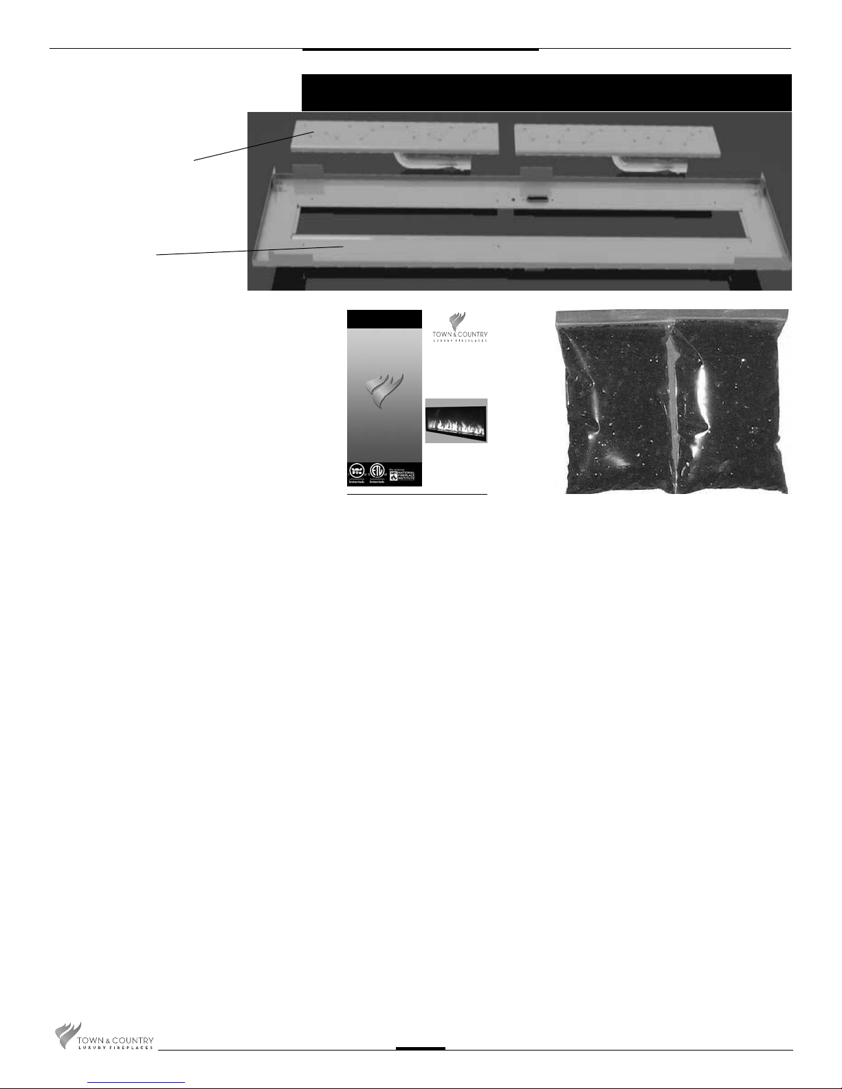
2 BURNER ASSEMBLIES
1 BURNER TRAY
Contents of Package
IMPORTANT:
THESE INSTRUCTIONS ARE TO REMAIN
WITH THE HOMEOWNER
These instructions are supplementary to the Installation
and Operating Instructions supplied with the replace
and should be kept together. Refer to the Installation
and Operating Instructions for proper gas supply, safety
requirements and operating instructions.
TCWS.54NG03C2
BLACK DIAMOND
BURNER KIT
INSTRUCTIONS
PART# TCWS.54NG03C2
For Model: TCWS54
Series: C2
020611-12 5056.42521032 TCWS.54NG03C2
1 INSTRUCTION PACK
2 5 LB GLASS MEDIA
TCWS.54NG03C2 230911-12
2
Black Diamond Burner Installation
If converting to propane see
conversion instructions on page #5
before proceeding.
Install panels according to the
TCWS.54CE2 Installation and
Operating manual prior to burner
installation. (Page 23)
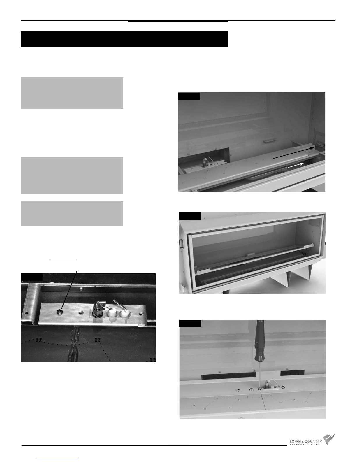
1. Install the right burner by laying into
location trough and sliding to the right
to engage the venturi tube over the
ori ce. Repeat with left burner. (Fig.
#1)
NOTE: check air shutter for correct fuel
setting before proceeding further. Both
burner shutters are to be set the same,
fully closed for natural gas. 13/64 (0.2)”
open for LP.
CAUTION: The burners should be tightly
butted up against each other at the center
to ensure correct operation.
Fig #1
Fig #2
2. Tilt the burner tray into the unit and place
on top of the manifold brackets(Fig.#2).
Attach pilot to burner tray. Be sure pilot
is attached to burner support rail with
screw in rst hole position.
(Fig. #2a)
Fig #2a
3. Secure the burner tray to manifold
brackets using eight screws(Fig. #3).
FIRST HOLE POSITION
Fig #3
TCWS.54NG03C2 230911-12
3
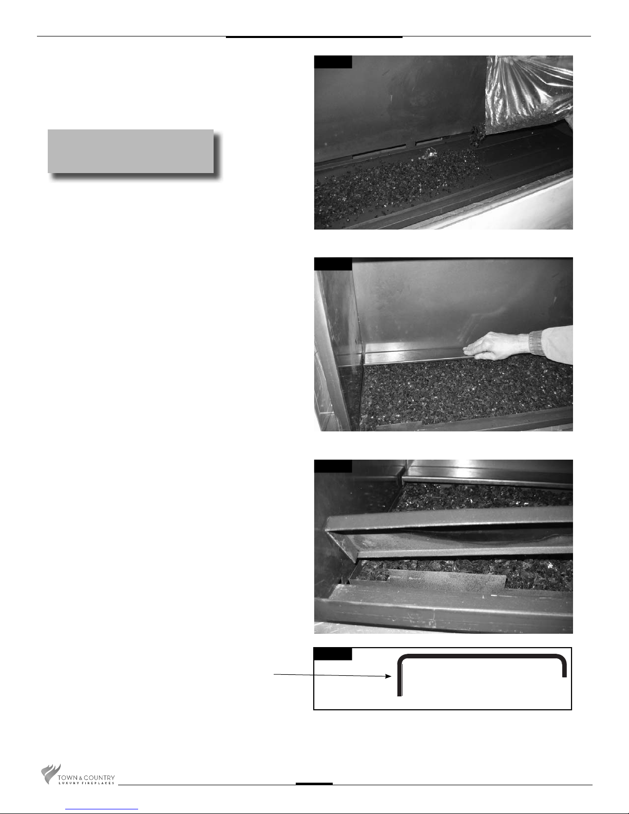
4. Place glass media into the burner
tray and brush smooth so that a
very light layer covers the burners.
(Fig. #4)
NOTE: Too much glass media will
cause sooting and improper ame
pattern.
5. Place rear porcelain trim, wide
edge, against the back panel and
press down over the pre-bent tabs
on the burner tray. (Fig. #5)
Fig #4
Fig #5
6. Place the front porcelain trim so
that it rests on the front shelf of
the rebox and is snug against the
rebox frame.
Ensure that the wide edge of the
trim is against the rebox frame.
(Fig. #6 & 7)
WIDE EDGE TO FRONT OF
FIREPLACE WITH FRONT
TRIM, TO THE REAR OF THE
FIREBOX FOR REAR TRIM.
Fig #6
Fig #7
TCWS.54NG03C2 230911-12
4
 Loading...