

Town & Country Fireplaces D2 Series, TCWS54 Booklet

FOR ARCHITECTS & DESIGNERS
TCWS54
SERIES D2
100001172-50 TCWS54D2
Dimensions | Clearances | Venting
IMPORTANT
This booklet is intended as a basic specification
guide for architects, designers and builders.
Please refer to the Instruction Manual supplied
with the fireplace for detailed information regarding
installation and operation.
Product installation manuals can also be viewed at:
www.townandcountryfireplaces.com
021118-12
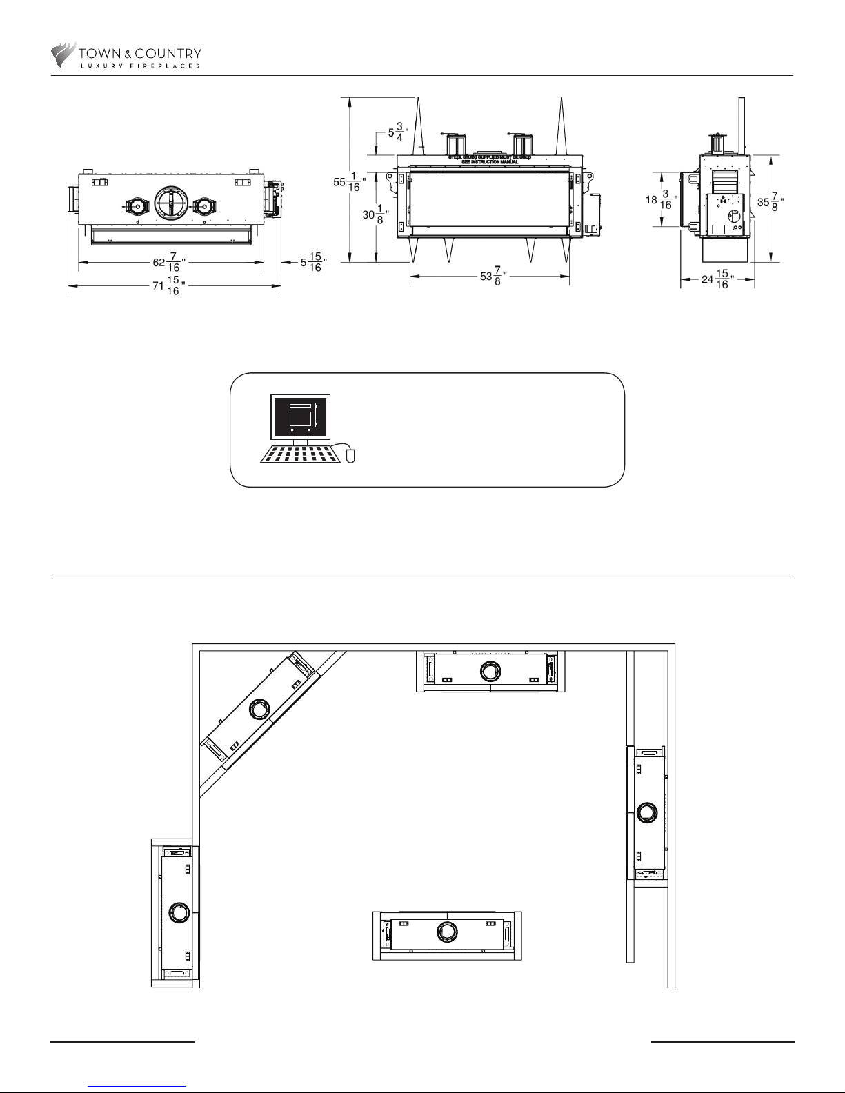
Fireplace Dimensions
TCWS54.D2 Cad Drawing
Available at
www.townandcountryreplaces.com
Examples of Common Locations
021118-12
FOR REFERENCE ONLY. CONSULT MANUAL BEFORE INSTALLATION
2
100001172-50 TCWS54D2
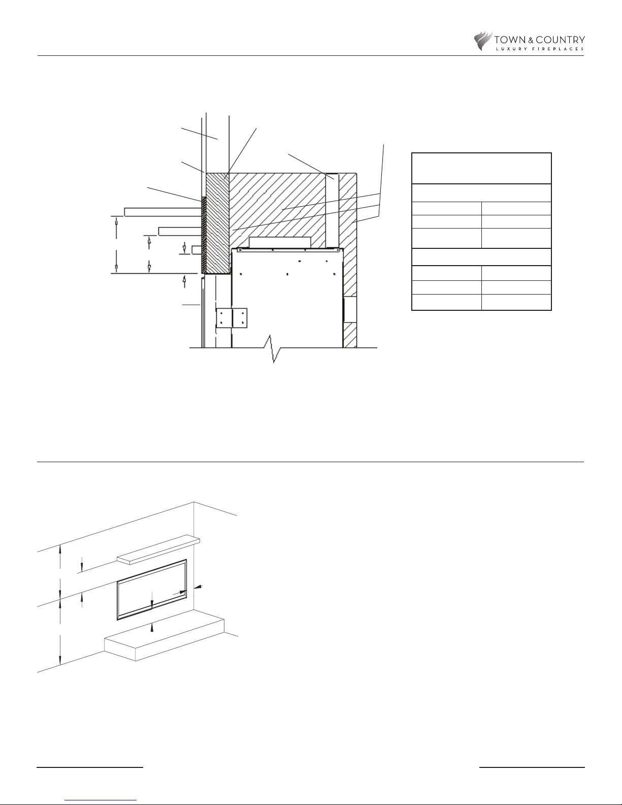
Mantel Clearance Chart
29 3/4"
24"
4“
CEILING
ADJACENT WALL
OR MANTEL SUPPORT
12”
COMBUSTIBLE FLOOR
COMBUSTIBLE HEARTH
*
**
COMBUSTIBLE FRAMING AND
FINISH WALL ABOVE STANDOFFS
MAY USE COMBUSTIBLE
FACING MATERIAL IN THIS
AREA
NON-COMBUSTBLE
FINISH MATERIAL
A
TOP OF LINTEL BAR
FIREPLACE
FRONT
D
E
F
B
C
STEEL FRAMING
STANDOFF
NON-COMBUSTIBLE ZONE.
DO NOT INSTALL ANY COMBUSTIBLE
MATERIAL, ELECTRICAL WIRING OR GAS
PLUMBING IN THIS AREA.
MANTEL CLEARANCE
CHART
* MANTEL CLEARANCE
A 9”
B 6”
C 3”
** MANTEL DEPTH
D 12”
E 6 3/4”
F 1 1/2”
Minimum Clearances to Combustibles
Minimum Clearances:
Side standoffs .................................................. 0 in. (0 mm)
Back standoffs ................................................. 0 in. (0 mm)
Top standoffs .................................................... 0 in. (0 mm)
Bottom of appliance ......................................... 0 in. (0 mm)
Adjacent side wall ............................................. 4 in. (102 mm)
Ceiling to appliance .......................................... 24 in. (610 mm)
*Mantel to appliance .......................................... See mantle clearance
.................................................................... chart above
**Maximum Mantel extension ............................. See mantle clearance
..................................................................... chart above
Mantel support ................................................. 4 in. (102 mm)
Vertical vent pipe ............................................. 1 3/4" in.(45 mm)
Horizontal Vent pipe (Top, sides and bottom) .... 1 3/4" in.(45 mm)
MANTEL
Unit may be recessed up to 4 1/2” with
non-combustible masonary type material
100001172-50 TCWS54D2
FOR REFERENCE ONLY. CONSULT MANUAL BEFORE INSTALLATION
3
021118-12
31 1/2"
44 9/16"
74 13/16"
81 11/16"
81 11/16"
115 9/16"
55 1/4"
74 13/16"
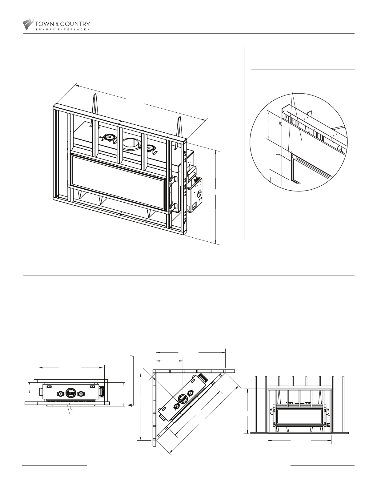
NOTE: FIREPLACE SHOULD BE IN ITS FINAL LOCATION BEFORE FRAMING
RANGE
23 11/16"
to
25 7/16"
RANGE
25 3/8”
to
26 7/8"
RANGE
1/32"
to
3 3/16"
11 3/4"
FRAMING
LINTEL
74 3/4"
Framing kit is supplied
with Fireplace
Steel Stud Framing Kit Dimensions Kit
Non-combustible
All other framing can be done with
conventional lumber
Board Detail
NON-COMBUSTIBLE BOARD
74 3/4"
12”
9 5/8”
12”
55 1/16"
NON-COMBUSTIBLE materials
must extend 12” above and 9 5/8”
to the sides of the framing edges.
NON-COMBUSTIBLE BOARD NOT
INCLUDED.
Minimum Combustible Framing Dimensions
NOTE: Fireplace should be in its final location before framing.
NOTE: Combustible framing must allow for sheetrock installation.
Must allow for
minimum 1/2 inch
gap for non-combustible
board and facing
FOR REFERENCE ONLY. CONSULT MANUAL BEFORE INSTALLATION
021118-12
4
100001172-50 TCWS54D2
 Loading...