

Town & Country Fireplaces TCWS38, TCWS.38NG04.C Instructions For Intallation

INSTALLER: Leave this manual with the appliance.
CONSUMER: Retain this manual for future reference.
These instructions are supplementary to the Installation
and Operating Instructions supplied with the replace
and should be kept together. Refer to the Installation
and Operating Instructions for proper gas supply, safety
requirements and operating instructions.
TCWS.38NG04.C
TRANQUILITY
BURNER KIT
INSTRUCTIONS
050809-16 5056.4252204 TCWS.38NG04.C
PART# TCWS.38NG04.C
For use with
Model TCWS38
Series C
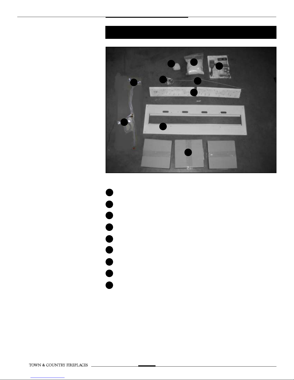
Contents of Package
A
I
I
1 5.0 LBS SAND
E
G
C
A
B
D
F
H
B
C
D
E
F
G
H
1 HARDWARE PACK
1 EQUALIZER ROCK
1 1/4 SS PILOT SUPPLY TUBE
1 PILOT ASSEMBLY
2 BURNER ASSEMBLIES
1 BURNER TRAY ASSEMBLY
3 PEBBLE SETS
2 MANIFOLD BRACKETS WITH 1/2” SS
I
FUEL SUPPLY TUBES
TCWS.38NG04.C 050809-16
2
Tranquility Burner Installation
Fig #1
Fig #2
If converting to propane see conversion instructions on page #8 before
proceeding.
Install panels according to the
TCWS.38CE Installation and
Operating manual prior to burner
installation. (Page 23)
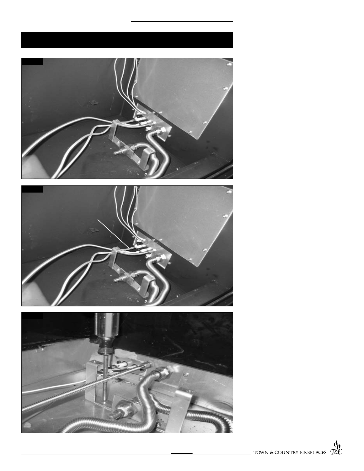
1. Attach the manifold brackets, with the
fuel supply tubes, to the bottom of the
rebox using four screws. (Fig. #3)
2. Remove Pilot and support bracket
from burner tray.
3. Attach fuel supply tube and pilot
assembly to bulkhead ttings.
(Fig. #1)
RED END
Fig #3
4. Connect spark electrode wire
(RED END) to the rear electrical bulk
head tting. Connect the ame
sensor wire(WHITE END) to the front
electrical bulk head tting. (Fig. #2)
TCWS.38NG04.C 050809-16
3
CAUTION: Ensure that all connections
are gas tight.
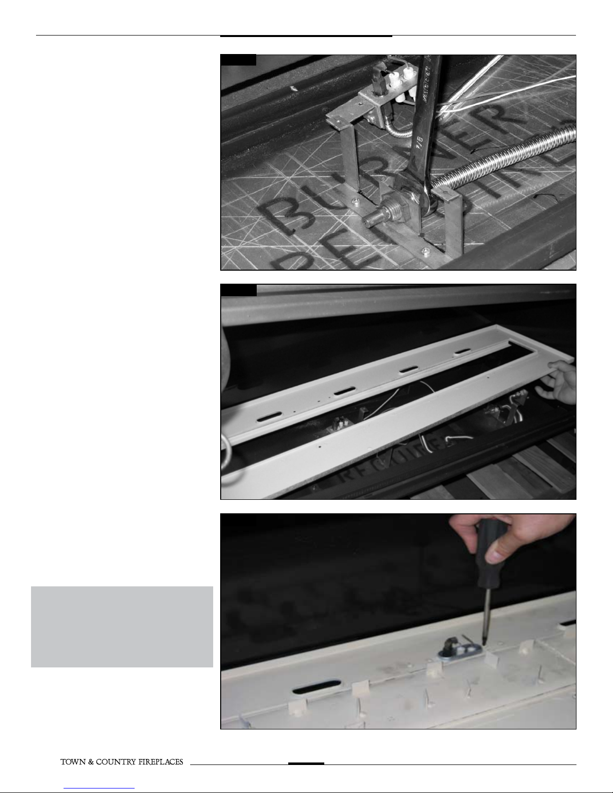
Fig #4
4. Tilt burner tray length-wise and insert
into the rebox.
(Fig. #5)
5. Attach pilot to burner tray. (Fig. #6)
Fig #5
Fig #6
NOTE: Ensure tht the pilot is tight up against
the burner tray.
TCWS.38NG04.C 050809-16
4
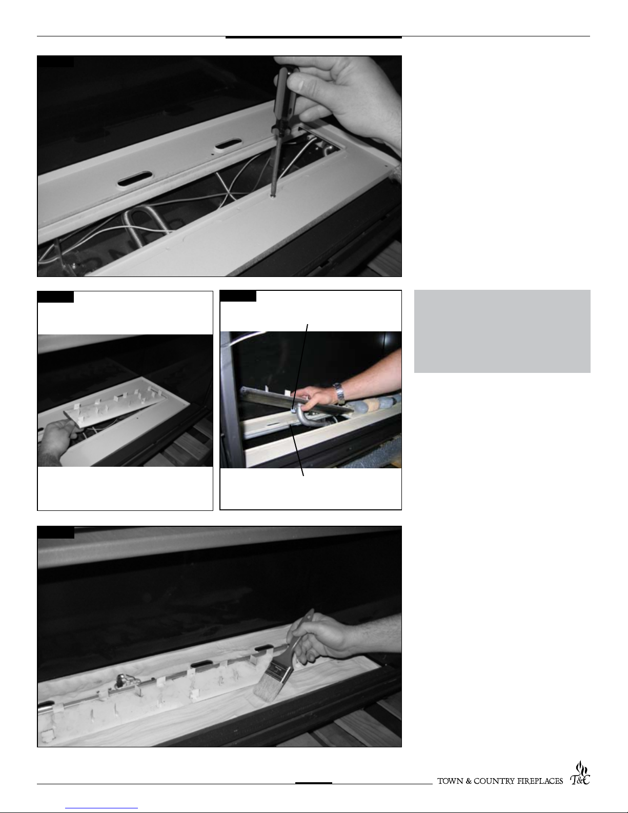
Fig #7
6. Secure the burner tray to legs using
six screws (Fig. #7)
NOTE: a light will aid aligning the holes
in the tray with the leg
Fig #8a
Fig #9
Fig #8b
LOCATOR TAB
SLOT
NOTE: check air shutter for correct
setting for fuel before proceeding
further. Both burners are the same.
Fully closed for natural gas.
13/64 (0.2)” open for LP.
7. Install the right burner by placing it into
the center of the burner tray. With the
left end elevated slightly, slide it to the
far right. The primary air shutter should
engage fully with the main orice.Test
for connection by lifting at a location
pin on the right side of the burner.
Repeat with left burner being sure that
alignment tab engages in the slot in
burner tray. (Fig. #8a & #8b)
8. Continue with panel installation.
CAUTION: The burners should be tightly
butted up against each other at the center
to ensure correct operation.
TCWS.38NG04.C 050809-16
9. Place sand into the burner tray and
brush smooth. Use caution not to get
sand near the burner ports. (Fig. #9)
5
 Loading...