

Town & Country Fireplaces TCWS.38NG03.C Instructions Manual

IMPORTANT:
THESE INSTRUCTIONS ARE TO REMAIN
WITH THE HOMEOWNER
These instructions are supplementary to the Installation
and Operating Instructions supplied with the replace
and should be kept together. Refer to the Installation
and Operating Instructions for proper gas supply, safety
requirements and operating instructions.
TCWS.38NG03.C
BLACK DIAMOND
BURNER KIT
INSTRUCTIONS
080709-12 5056.4252203 TCWS.38NG03.C
PART# TCWS.38NG03.C
For use with
Model TCWS38
Series C
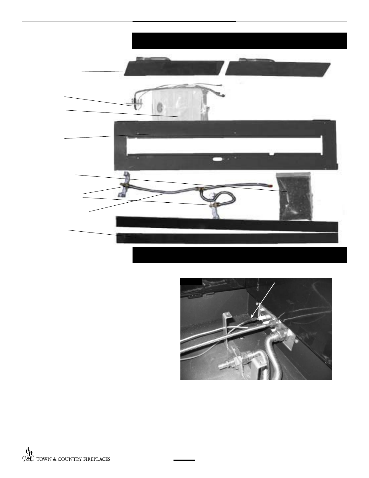
2 BURNER ASSEMBLIES
1 PILOT ASSEMBLY
1 HARDWARE PACK
1 BURNER TRAY
1 5 LB GLASS MEDIA
2 MANIFOLD ASSEMBLIES
1 1/2 SS FUEL SUPPLY TUBE
Contents of Package
2 PORCELAIN TRIM
Black Diamond Burner Installation
If converting to propane see conversion
instructions on page #6 before proceeding.
Install panels according to the TCWS.38CE
Installation and Operating manual prior to
burner installation. (Page 27)
1 Attach fuel supply tube and pilot assembly to bulk-
head ttings. Ensure the fuel supply tube travels
around the mounting leg towards the front of the
rebox as shown. (Fig. #1)
2. Connect spark electrode wire (ORANGE) to the
rear electrical bulk head tting. Connect the ame
sensor wire (WHITE) to the front electrical bulk
head tting. (Fig. #1)
Fig #1
ORANGE WIRE
TCWS.38NG03.C 080709-12
2
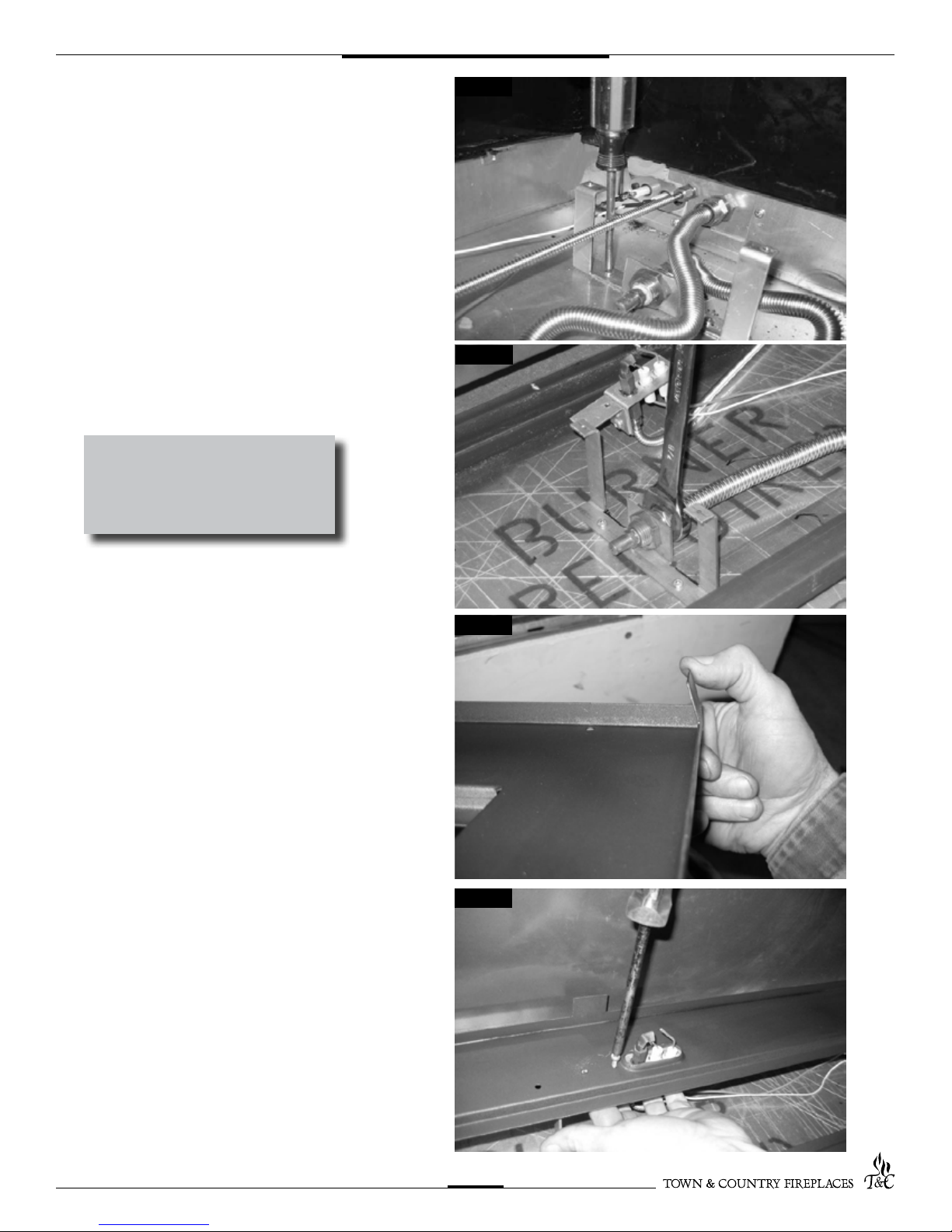
3. Attach the manifold brackets, with the
supply tubes, to the bottom of the rebox
using four screws. (Fig. #2)
CAUTION:
Ensure that all connections are gas
tight.
Fig #2
Fig #3
4. Bend side tabs on burner tray inwards
about 20° or 1/2”. (Fig. #4)
5. Tilt the burner tray into the unit and place
on top of the legs. Attach pilot to burner
tray. Ensure pilot is tight to burner tray.
(Fig. #5)
Fig #4
Fig #5
TCWS.38NG03.C 080709-12
3
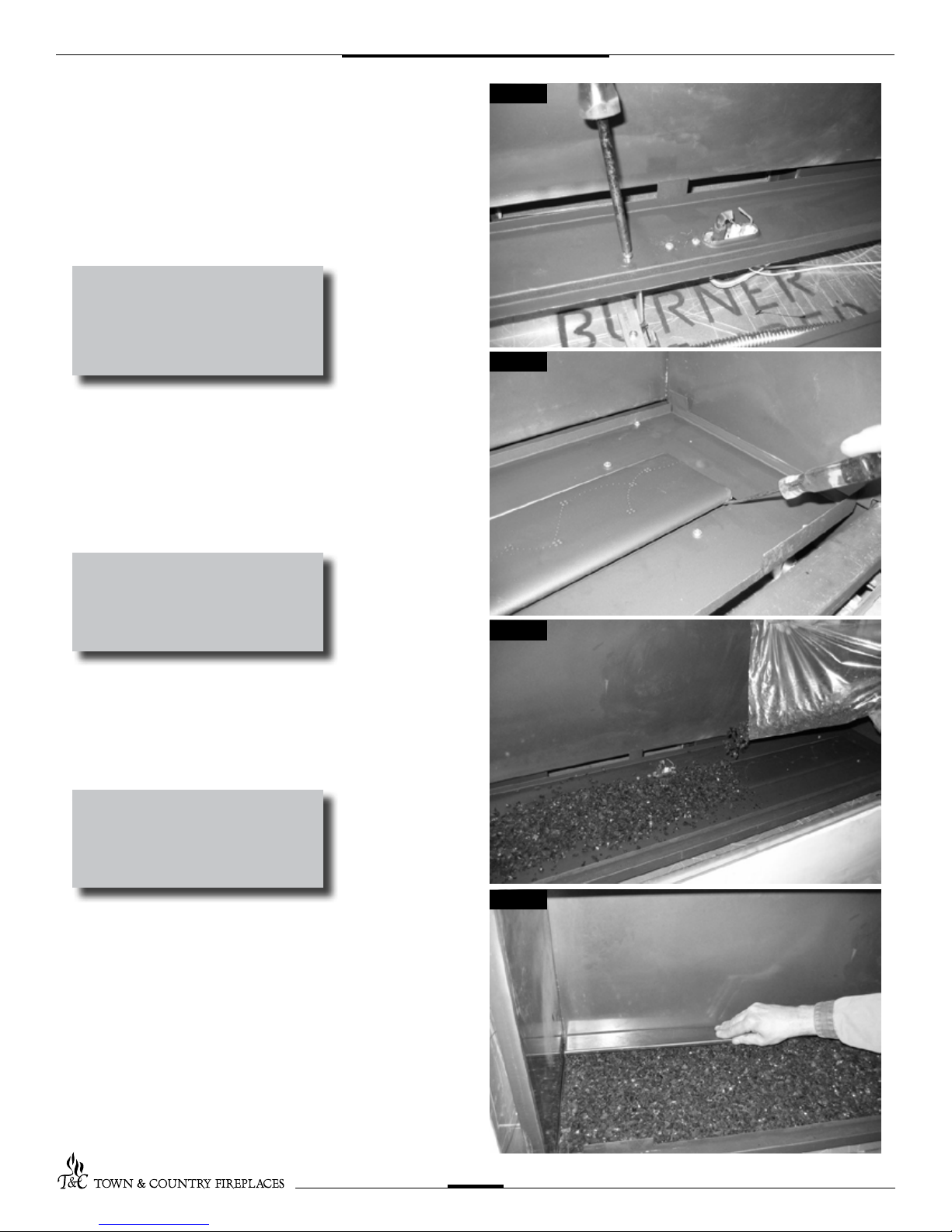
6. Secure the burner tray to legs using
eight screws (Fig. #6)
NOTE: use a light to aid aligning the
holes in the tray with the leg.
NOTE: check air shutter for correct
setting for fuel before proceeding
further. Both primary air shutters
are to be set the same, fully closed
for natural gas. 1/8” (0.125)” open
for LP.
7. Install the right burner rst by plac-
ing it into the center of the burner tray.
With the left end slightly elevated, slide
it to the far right. The primary air shutter
should engage fully with the main orice.
Test for connection by lightly prying at
the end of the burner with a screw driver.
Repeat with left burner. (Fig. #7)
Fig #6
Fig #7
NOTE: The burners should be tightly
butted up against each other at the
center to ensure correct operation.
8. Place glass media into the burner
tray and brush smooth so that a
very light layer covers the burners.
(Fig. #8)
NOTE: Too much glass media will
cause sooting and improper ame
pattern.
9. Place rear porcelain trim, wide
edge, against the back panel and
press down over the pre-bent tabs
on the burner tray. (Fig. #9)
Fig #8
Fig #9
TCWS.38NG03.C 080709-12
4
 Loading...