

Town & Country Fireplaces TCWS38 C Series Installation And Operating Instructions Manual
INSTALLER: Leave this manual with the appliance.
CONSUMER: Retain this manual for future reference.
WARNING: If the information in these
instructions is not followed exactly, a re or
explosion may result causing property damage,
personal injury or death.
FOR YOUR SAFETY
Installation and service must be performed
by a qualied installer, service agency or the
gas supplier.
TCWS.38CE
INSTALLATION
WHAT TO DO IF YOU SMELL GAS
r %POPUUSZUPMJHIUBOZBQQMJBODF
r %POPUUPVDIBOZFMFDUSJDBMTXJUDI
r%POPUVTFBOZQIPOFJOZPVSCVJMEJOH
r *NNFEJBUFMZDBMMZPVSHBTTVQQMJFSGSPN
a neighbour’s phone. Follow the gas
supplier’s instructions.
r *GZPVDBOOPUSFBDIZPVSHBTTVQQMJFSDBMM
the re department.
Do not store or use gasoline or other ammable
vapors and liquids in the vicinity of this or any
other appliance.
This appliance may be installed in an aftermarket
permanently located, manufactured home (USA
only) or mobile home, where not prohibited by
local codes.
This appliance is only for use with the type of gas
indicated on the rating plate. This appliance is
not convertible for use with other gases, unless
a certied kit is used.
AND OPERATING
INSTRUCTIONS
MODEL
TCWS38
SERIES C
MODULAR DIRECT VENT
FIREPLACE
This appliance is suitable for installation in a
bedroom or bed sitting room.
TCWS.38.CE 300709-44 5056.42522

Table of Contents
Hot Glass WARNING ......................................................................3
Caution ...........................................................................................3
Safety .............................................................................................3
Important Note for the Commonwealth of Massachusetts: ............. 4
Fireplace Dimensions ..................................................................... 5
Minimum Clearances to Combustible Material ...............................5
Installation Requirements ............................................................... 6
Manufactured (Mobile) Home .........................................................6
Window Frame Removal .................................................................6
Standoffs.........................................................................................7
Locating The Fireplace ...................................................................7
Framing and Finishing ....................................................................8
Steel Stud Framing Kit ................................................................. 10
Maestro Control ........................................................................... 13
– Plumbing and Electrical ............................................................. 13
Gas Pressure Check ..................................................................... 15
Gas Supply ................................................................................... 15
Venting .......................................................................................... 16
Wall Termination Venting .............................................................. 16
Wall Termination Venting Chart ..................................................... 19
Roof Termination Venting Chart .................................................... 20
Vent Terminal Clearance ...............................................................23
Vent Pipe Sealant .........................................................................24
Vent Restrictor Adjustment ...........................................................25
Firebox Panels Installation ............................................................ 26
Quick Panel Removal for Valve Service ........................................ 27
Finishing Touch Trim Kit Instructions .............................................28
Lighting Instructions .....................................................................29
First Fire ........................................................................................ 29
Maestro Control System ...............................................................30
Remote Control Initial Setup ......................................................... 30
Maestro Control System - Operation ............................................31
Maintenance ................................................................................. 34
TCWS.38CE Replacement Parts .................................................35
Replacement Parts – Maestro Control System .............................36
Fireplace Lighting .........................................................................38
Wiring Diagram .............................................................................38
Roof and Wall Termination Kit .....................................................39
Vent Pipe Dimensions .................................................................40
Vent Offset Chart ..........................................................................41
Safety Label Location ................................................................... 43
TCWS.38CE 300709-44
2
Caution
FOR YOUR SAFETY - Do not install or operate your Town & Country replace without
rst reading and understanding this manual. Any installation or operational deviation from
the following instructions voids the Town & Country Fireplaces
hazardous.
This appliance and its individual shut off valve must be disconnected from gas supply piping system during any pressure testing of that system at test pressures in excess of 1/2
psig (3.5 kPa).
This appliance must be isolated from the gas supply piping system by closing its individual
manual shut off valve during any pressure testing of the gas supply piping system at test
pressures equal to or less than 1/2 psig (3.5 kPa).
Note: When lit for the rst time, the appliance will emit a slight odour for a couple of hours.
This is due to the curing of paints, sealants and lubricants used in the manufacturing process.
This condition is temporary. Open doors and windows to ventilate area. Smoke and fumes
caused by the curing process may cause discomfort to some individuals.
Do not use the replace if any part has been under water. Immediately call a qualied service
technician to inspect the replace and to replace any part of the control system and any gas
control which has been under water.
TM
Warranty and may prove
Safety
Due to high temperatures, this gas appliance should be located out of traffic and away from
furniture and draperies.
Children and adults should be alerted to the hazards of high surface temperatures and
should stay away to avoid burns or clothing ignition.
Young children should be carefully supervised when they are in the same room as the
appliance. Toddlers, young children and others may be susceptible to accidental contact
burns. A physical barrier is recommended if there are at risk individuals in the house. To
restrict access to the replace or stove, install an adjustable safety gate to keep toddlers,
young children and other at risk individuals out of the room and away from hot surfaces.
Clothing or other ammable material should not be placed on or near the appliance.
Any grill, panel or door removed for servicing the unit must be replaced prior to operating.
Failure to do so may create a hazardous condition.
Installation and repair should be done by a qualied service person. The appliance should
be inspected before use and at least annually by a professional service person. More
frequent cleaning may be required due to excessive lint from carpeting, bedding material,
etc.. It is imperative that control compartments, burners and circulating air passageways
of the appliance be kept clean.
It is our policy that no responsibility is assumed by the Company or by any of its employees
or representatives for any damages caused by an inoperable, inadequate, or unsafe
condition which is the result, either directly or indirectly, of any improper operation or
installation procedures.
This appliance must not be connected to a chimney ue serving a separate solid fuel
burning appliance.
TCWS.38CE 300709-44
3

Important Note for the Commonwealth of Massachusetts:
From Massachusetts Rules and Regulations 248 CMR 5.08:
(a) For all side wall horizontally vented gas fuelled equipment installed in every dwelling, building or structure used in whole or in part for residential
purposes, including those owned or operated by the Commonwealth and where the side wall exhaust vent termination is less than seven (7) feet above
nished grade in the area of the venting, including but not limited to decks and porches, the following requirements shall be satised.
1. INSTALLATION OF CARBON MONOXIDE DETECTORS. At the time of installation of the side wall horizontal vented gas fuelled equipment, the
installing plumber or gas tter shall observe that a hard wired carbon monoxide detector with an alarm and battery back-up is installed on the oor level
where the gas equipment is to be installed, in addition, the installing plumber or gas tter shall observe that a battery operated or hard-wired carbon
monoxide detector with an alarm is installed on each additional level of the dwelling, building or structure served by the side wall horizontal vented gas
fuelled equipment. It shall be the responsibility of the property owner to secure the services of qualied licensed professionals for the installation of
hard-wired carbon monoxide detectors.
a. In the event that the side wall horizontally vented gas fuelled equipment is installed in a crawl space or an attic, the hard-wired carbon monoxide
detector with alarm and battery back-up may be installed on the next adjacent oor level.
b. In the event that the requirements of this subdivision cannot be met at the time of completion of installation, the owner shall have a period of thirty
(30) days to comply with the above requirements; provided, however, that during said thirty (30) day period, a battery operated carbon monoxide detec-
tor with an alarm shall be installed.
2. APPROVED CARBON MONOXIDE DETECTORS. Each carbon monoxide detector as required in accordance with the above provisions shall
comply with NFPA 720 and be ANSI/UL 2034 listed as IAS certied.
3. SIGNAGE. A metal or plastic identication plate shall be permanently mounted to the exterior of the building at a minimum height of eight (8) feet
above grade directly in line with the exhaust vent terminal for the horizontally vented gas fuelled heating appliance or equipment. The sign shall read, in
print size no less than one-half (1/2) inch in size, “GAS VENT DIRECTLY BELOW. KEEP CLEAR OF ALL OBSTRUCTIONS”.
4. INSPECTION. The state or local gas inspector of the side wall horizontally vented gas fuelled equipment shall not approve the installation unless,
upon inspection, the inspector observes carbon monoxide detectors and signage installed in accordance with the provisions of 248 CMR 5.089(2)(a) 1
through 4.
(b) EXEMPTIONS. The following equipment is exempt from 248 CMR 5.089(2)(a) 1 through 4.
1. The equipment listed in Chapter 10 entitled “Equipment Not Required To Be Vented” in the most current edition of NFPA 54 as adopted by the
Board; and
2. Product Approved side wall horizontal vented gas fuelled equipment installed in a room or structure separate from the dwelling, building or struc-
ture used in whole or in part for residential purposes.
(c) MANUFACTURER REQUIREMENTS – GAS EQUIPMENT VENTING SYSTEM PROVIDED. When the manufacturer of Product Approved side
wall horizontally vented gas equipment provides a venting system design or venting system components with the equipment, the instructions provided by
the manufacturer for installation of the equipment and the venting system shall include:
1. Detailed instructions for the installation of the venting system design or the venting system components; and
2. A complete parts list for the venting system design or venting system.
(d) MANUFACTURER REQUIREMENTS – GAS EQUIPMENT VENTING SYSTEM NOT PROVIDED. When the manufacturer of a Product Approved
side wall horizontally vented gas fuelled equipment does not provide the parts for venting the fuel gases, but identies “special venting systems”, the fol-
lowing requirements shall be satised by the manufacturer.
1. The referenced “special venting system” instructions shall be included with the appliance or equipment installation instructions; and
2. The “special venting systems” shall be Product Approved by the Board, and the instructions for that system shall include a parts list and detailed
installation instructions.
(e)) A copy of all installation instructions for all Product Approved side wall horizontally vented gas fuelled equipment, all venting instructions, all parts
lists for venting instructions, and/or all venting design instructions shall remain with the appliance or equipment at the completion of the installation.
TCWS.38CE 300709-44
4
21 5/8"
24"
4“
*
CEILING
ADJA
CENT
WALL
OR MANTEL SUPPORT
6”
COMBUSTIBLE FL
OOR
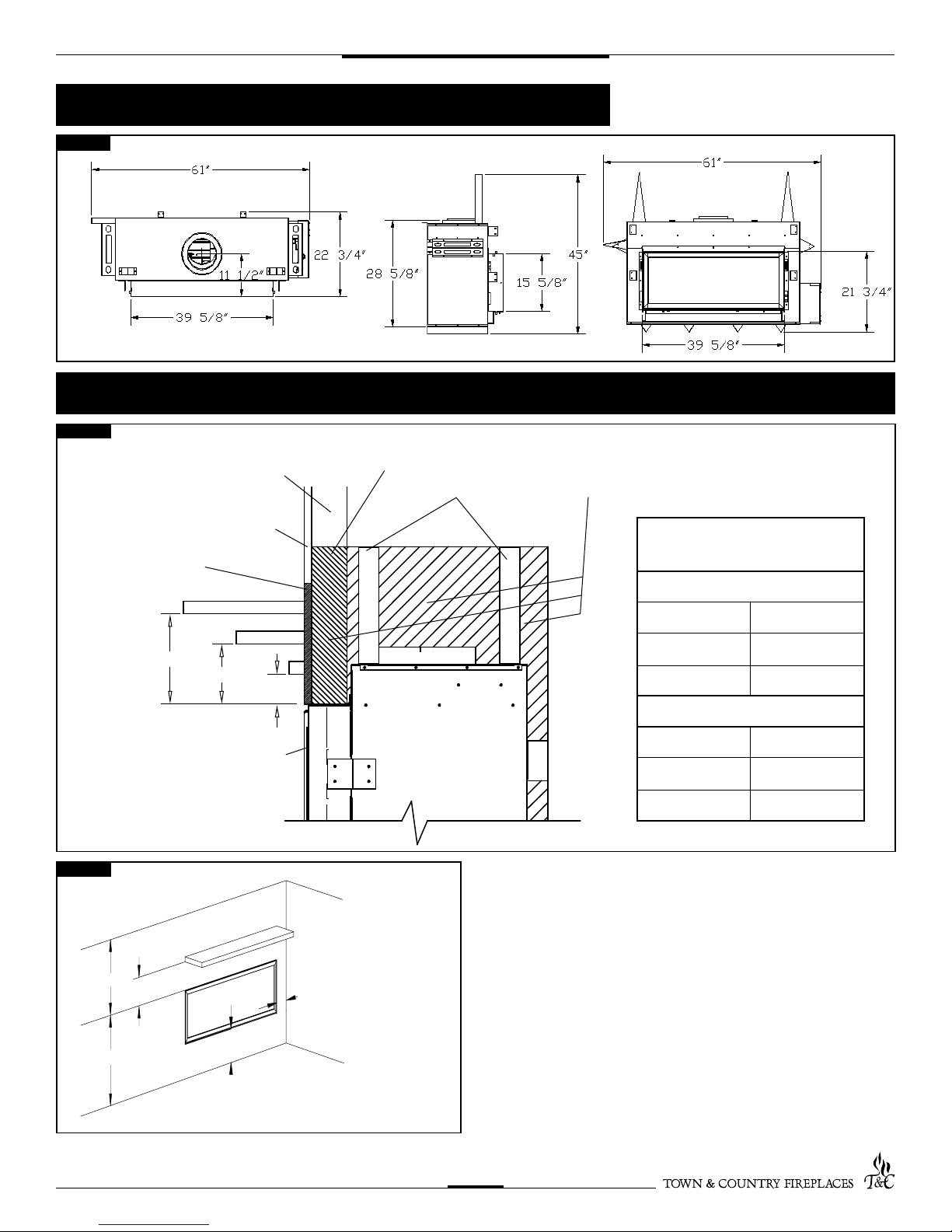
Fireplace Dimensions
Fig. #1
Minimum Clearances to Combustible Material
Fig. #2
COMBUSTIBLE FRAMING AND
FINISH WALL ABOVE STANDOFFS
MAY USE COMBUSTIBLE
FACING MATERIAL IN THIS AREA
NON-COMBUSTIBLE
FINISH MATERIAL
SEE FIG #7
A
TOP OF LINTEL BAR
FIREPLACE FRONT
Fig. #3
TCWS.38CE 300709-44
D
E
F
B
C
UNIT MAY BE RECESSED UP TO 6” WITH
NONCOMBUSTIBLE MASONRY TYPE MATERIAL
STEEL FRAMING
STANDOFFS
NON-COMBUSTIBLE ZONE.
DO NOT INSTALL ANY COMBUSTIBLE MATERIAL, ELECTRICAL WIRING OR GAS PLUMBING
IN THIS AREA.
MANTEL CLEARANCE
CHART
* MANTEL CLEARANCE
A 9”
B 6”
C 3”
** MANTEL DEPTH
D 12”
E 6 3/4”
F 1 1/2”
Minimum Clearances:
Side standoffs ....................................................... 0 in. (0 mm)
Back standoffs ......................................................0 in. (0 mm)
Top standoffs ........................................................0 in. (0 mm)
Bottom of appliance .............................................. 0 in. (0 mm)
Adjacent side wall ................................................. 4 in. (102 mm)
Ceiling to appliance ............................................ 24 in. (610 mm)
*Mantel to appliance .................. ..........See Figure #2
**Maximum Mantel extension .. ..........See Figure #2
Mantel support ...................................................... 4 in. (102 mm)
Vertical vent pipe ..........................................1 3/4" in. (45 mm)
5
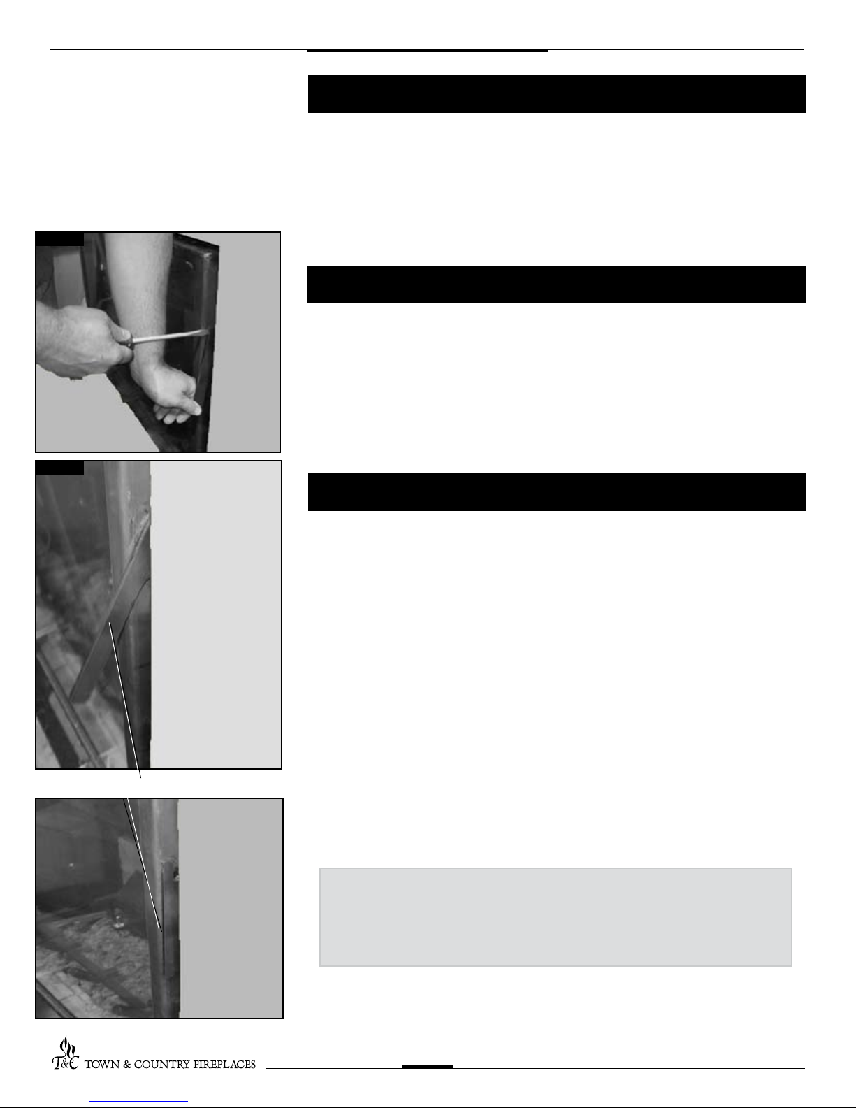
Fig. #4
Fig. #5
Installation Requirements
The Town & Country Fireplace installation and venting must conform to the current
CAN/CGA-B149.1 installation code (in Canada) or the current National Fuel Gas Code,
ANSI Z223.1/NFPA 54 (in the USA), and approved per local codes. Only qualied (licensed or trained) personnel should install this product.
In the state of Massachusetts, only a licensed Plumber and Gas Fitter may install
this product.
Manufactured (Mobile) Home
In some jurisdictions, the Town & Country Fireplace may be installed in Manufactured
Homes after the "rst sale". Consult local codes for approval. The replace must be
fastened in place.
Install in accordance with the current standard Mobile Homes, CAN/CSA Z240 MH (in
CANADA), and the Manufacturer's Home Construction and Safety Standard, Title 24 CFR,
Part 3280 or the current Standard for Fire Safety Criteria for Manufactured Home Installations, Sites and Communities ANSI/NFPA 501A (in the USA).
Window Frame Removal
LATCH HANDLE
FULLY CLOSED
POSITION
SHOWN.
Warning: Turn off the replace, and allow ample time for the unit to cool before
proceeding.
Caution: The ceramic glass is very fragile, and should be handled with care.
The window frame is held in place by two spring-loaded latches that are operated by a
one-piece latch handle.
1. Remove the TC Finishing Touch Trim Kit from the window frame. (If installed)
2. Using a screwdriver or other similar object, push against the notch in the top of the
latch and grab the bottom of the latch handle as it protrudes. Lift handle until latch hook
disengages. Repeat for other side while holding glass so it does not tip out.
3. Tilt the top of the window frame out to clear the top edge of the unit. Grasp the sides of
the frame and lift up and out to disengage from its bottom track.
4. Place the window frame in a safe place to avoid damage.
5. Re-assemble in reverse order. Latch handle should snap into place and be ush with
window frame when engaged correctly.
TIP:
To ensure glass is properly latched, grasp the top left and
right sides of the glass frame, under moderate pressure it
should pull forward and return to original position evenly on
both sides.
6. Reinstall Trim Kit if required.
TCWS.38CE 300709-44
6
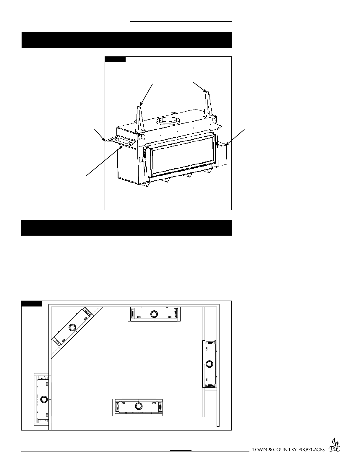
Standoffs
The standoffs are shipped loose
inside the replace and must be
installed on the top and the side of
the replace as shown in Fig. #6.
Do this once the replace is on
site and in position.
SIDE
STANDOFF
(THIS SIDE ONLY)
HANDLE
Fig. #6
Locating The Fireplace
TOP STANDOFFS
CONTROL
BOX
In planning the installation for the replace, it is necessary to determine where the unit is to
be installed, location of vent system and where gas supply piping may be plumbed. Various
installations are possible, such as, into an existing wall, a corner, a built-in wall or a wall
projection (Fig. #7). Due to high temperatures, do not locate this replace in areas of high
traffic or near furniture or draperies.
The minimum clearances from the replace to combustible surfaces must be adhered
to and are shown in Fig. #2 and Fig. #3.
Fig. #7
EXAMPLES OF COMMON LOCATIONS
SEE FIG #11 FOR DIMENSIONS
TCWS.38CE 300709-44
7
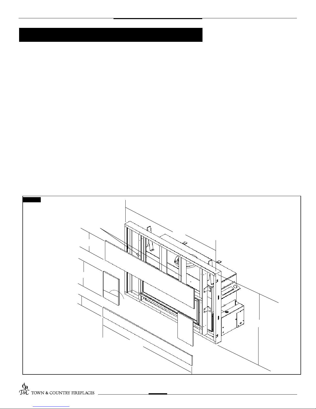
Framing and Finishing
Note: The replace should be in place
and venting installed before framing in or
building an enclosure around the unit.
The Town & Country replace must be framed
in as described below or totally enclosed with
non-combustible material, such as
facing brick.
Determine the total thickness of facing
material to be used. A thickness of 3/4" will
allow the nishing surface to be ush with
the front of the unit. If preferred, additional
masonry type non-combustible material can
be installed above and to the sides up to 6
inches proud of the appliance.
The nishing material must not interfere
with glass frame access.
A Steel Stud Framing Kit is supplied with the
replace and must be used unless the
replace is totally enclosed with
non-combustible material. Assemble the
framing kit as per the instructions on pages
10 – 13 of this manual. Attach the steel frame
to the replace once the replace is in its nal
position. Secure the steel frame to the framing
brackets on each side of the unit. Ensure that
the studs are set back far enough to allow
for thickness of nishing surface.
The sides, back and top of the replace can
be framed in up to the steel studs and the
replace standoffs using conventional
lumber. Consult local building codes for
specic requirements.
Due to high temperatures, non-combustible
board is supplied with the replace and must
be used to sheet in the front of the replace,
extending 6" below, 12” above and 10" to
the side of the framing edge bars. (Fig. #9)
Standard sheetrock (dry wall) may be used
beyond this.
If the backer board is not to be nished with
other non-combustible material such as tiles,
it is recommended that top sections of board
supplied with framing kit be replaced with
a single sheet of non-combustible board.
Taped and mudded joints may crack due to
the elevated temperatures.
Chase Insulation: When installing this
replace against a non-insulated exterior wall
or chase, it is recommended that the outer
walls be insulated to same degree as other
exterior walls. Do not place replace directly
against the insulation. Cover the insulation
and plastic vapour barrier with a solid surface,
such as dry wall (sheetrock). Consult local
codes. Do not insulate or use plastic vapour
barrier within the framing kit.
Fig. #8
NON-COMBUSTIBLE ZONE. DO NOT INSTALL ANY
COMBUSTIBLE MATERIAL, ELECTRICAL WIRING,
INSULATION, PLASTIC VAPOR BARRIER OR GAS
PLUMBING WITHIN THE STEEL STUD FRAMING
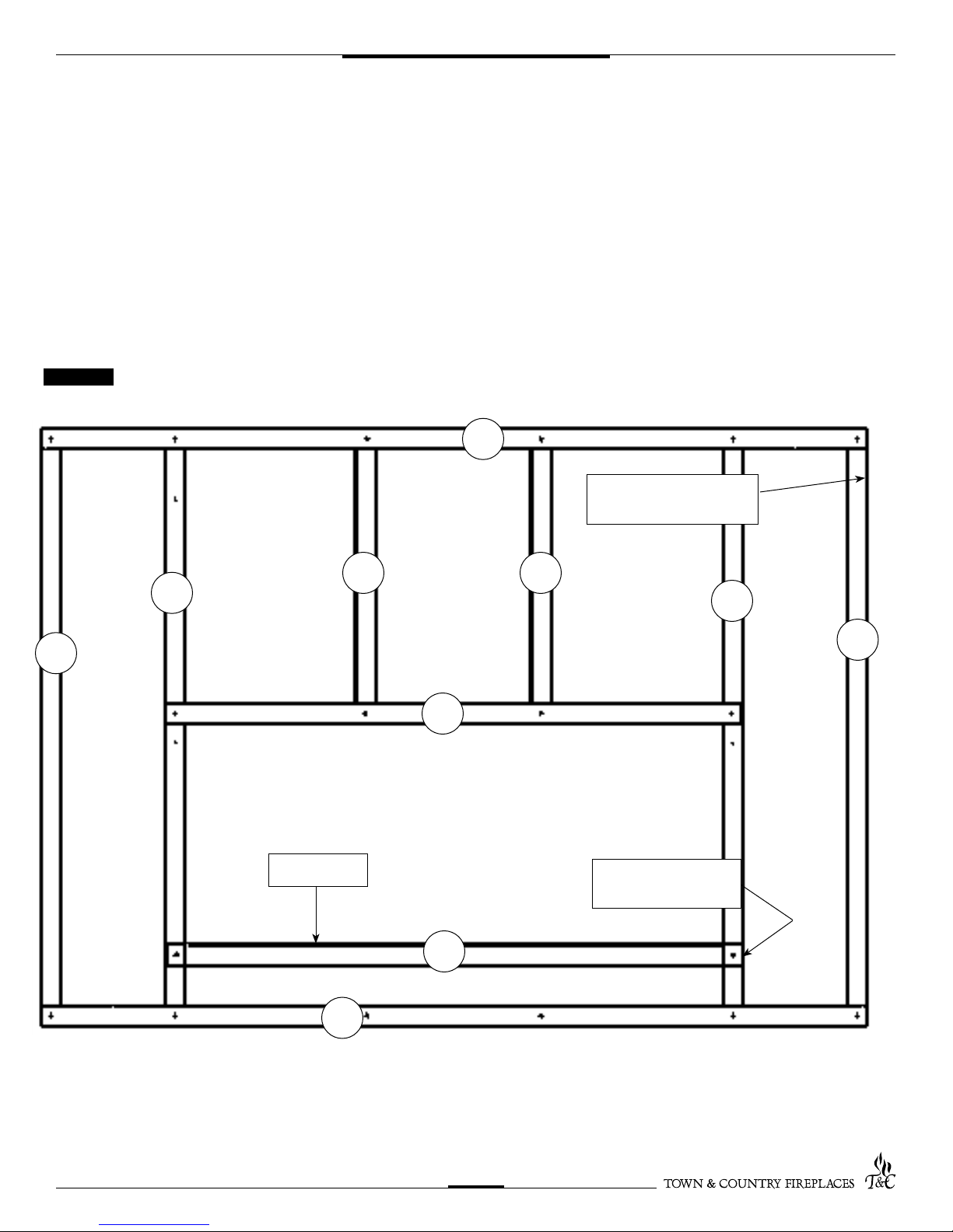
11 7/8”
15 7/8”
5 7/8”
10 1/8”
60”
STEEL STUD FRAMING KIT DIMENSIONS
(Supplied with replace)
ALL OTHER FRAMING CAN
61 1/2”
BE DONE WITH
CONVENTIONAL LUMBER
45”
TCWS.38CE 300709-44
8
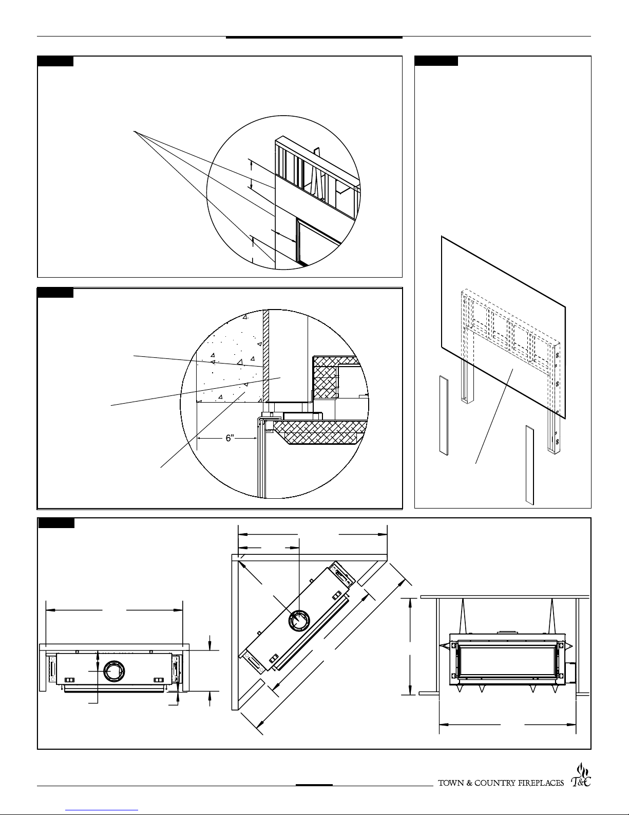
12”
10”
6”
61 1/2"
45"
61 1/2"
22 3/4"
11 5/16"
5/8"
71"
39 9/16"
28 7/16"
102"
61 1/2"
INCLUDING SHEETROCK
Fig. #9
NON-COMBUSTIBLE BOARD DETAIL
NON-COMBUSTIBLE
BOARD
NON-COMBUSTIBLE
MATERIAL MUST EXTEND
12" ABOVE AND 4 1/2"
TO THE SIDES OF THE
FRAMING EDGES.
Fig. #10
NON-COMBUSTIBLE RECESSED
INSTALLATION DETAIL
NON-COMBUSTIBLE
BOARD
Fig. #9A
IF THE BACKER BOARD IS NOT TO BE
FINISHED WITH OTHER NON-COMBUS-
TIBLE MATERIAL SUCH AS TILES, IT IS
RECOMMENDED THAT TOP SECTIONS
OF BOARD SUPPLIED WITH FRAMING KIT
BE REPLACED WITH A SINGLE SHEET OF
NON-COMBUSTIBLE BOARD. TAPED AND
MUDDED JOINTS MAY CRACK DUE TO
THE ELEVATED TEMPERATURES.
STEEL STUDS
NON-COMBUSTIBLE
MASONRY TYPE MATERIAL
Fig. #11
MINIMUM COMBUSTIBLE
FRAMING DIMENSIONS
NOTE: FIREPLACE SHOULD BE IN ITS FINAL LOCATION BEFORE FRAMING.
FULL SHEET OF A NONCOMBUSTIBLE MATERIAL
(NOT INCLUDED IN KIT)
TCWS.38CE 300709-44
9
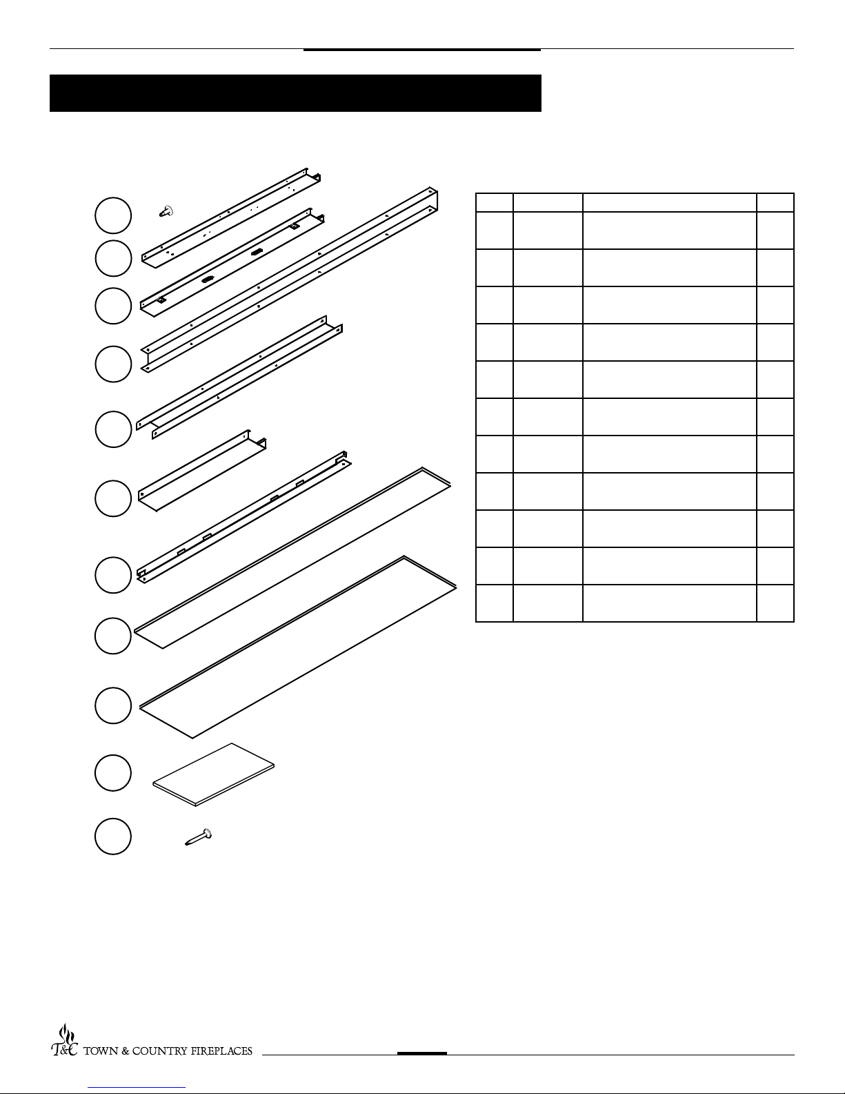
1
2
3
4
5
6
7
9
10
8
11
Steel Stud Framing Kit
Each Kit Contains:
TCWS.38FRKIT
Item Part # Description Qty.
1 5049.9912 SCREW, WAFER #8 x 1/2 Pkg
40
2 8393.4 STUD, SIDES 45” L 2
3 8393.2 STUD, OUTER SIDES 45” L 2
4 8393 STUD, UPPER/LOWER
61 1/2” L
5 8393.6 INNER CROSS BRACE
39 3/4” L
6 8393.8 STUD, CENTER 23 1/4” L 2
7 8393.9 LOWER CROSS BRACE
39 3/4” L
8 8394.2 NON-COMBUSTIBLE BOARD
BOTTOM 5 7/8” x 60”
9 8394.3 NON-COMBUSTIBLE BOARD
CENTER TOP 11 7/8” x 60”
10 8394.4 NON-COMBUSTIBLE BOARD
SIDES 10 1/8” x 15 7/8”
11 5049.993 SCREW, DRYWALL 1 1/4” Pkg
2
1
1
1
1
2
30
TCWS.38CE 300709-44
10
NOTE: Sheet metal parts have sharp edges, use caution when handling.
1. Frame Assembly
r Place one of #4 as a top.
r Place two of #6 into the top with the long edge facing up. Align the two holes and screw together with wafer screw #1.
r Attach #2 and #3 with wide edge face up.
r Attach #5 to #6 and #2.
r Attach #7 to #2 using one screw through the top and one screw through the side at each end.
r Place the one remaining piece of #4 at the bottom of the framing kit in the same manner as the top, screw them together and attach to the
inner steel studs.
r Turn the framing kit over and secure all studs from the back.
Fig. #12
3
FRONT VIEW (slightly angled)
4
BEND OUT FRAMING
TABS TO FRONT
6
2
5
6
2
3
SLOTS UP
TCWS.38CE 300709-44
SCREW INTO
SIDE
7
4
11
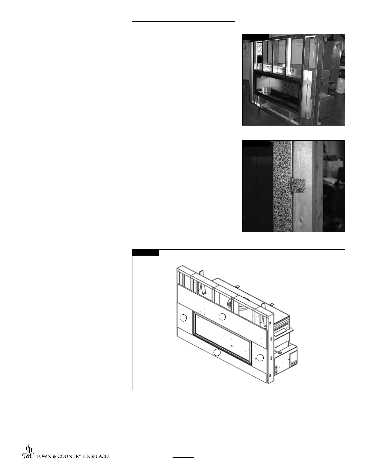
2. Attach the Assembled Frame to the
Unit
r Attach the framing kit to the unit.
(Fig. #13).
3. Secure to Existing Framing
r Bend out the tabs 90 degrees before
inserting the unit into its framed housing
(Fig. #14).
r Secure the frame assembly to the wood
frame through the tabs.
4. Install Non-Combustible Board Top
and Sides
r Use drywall screws, #11, to install the
non-combustible board top #9, bottom
#8, sides #10. (Fig. #15)
Fig. #13
Fig. #14
Fig. #15
10
9
8
10
TCWS.38CE 300709-44
12
Maestro Control
– Plumbing and Electrical
The gas control system is located on the right hand side of the rebox behind an access
panel and the decorative rebox panel (if installed). The replace is operated via a wall
switch and a hand held remote control unit.
The wall control is connected to the replace by a 25 ft. communication cable supplied with the
replace. The communication cable can be extended with an optional 25 ft. extension kit.
Fig. #16
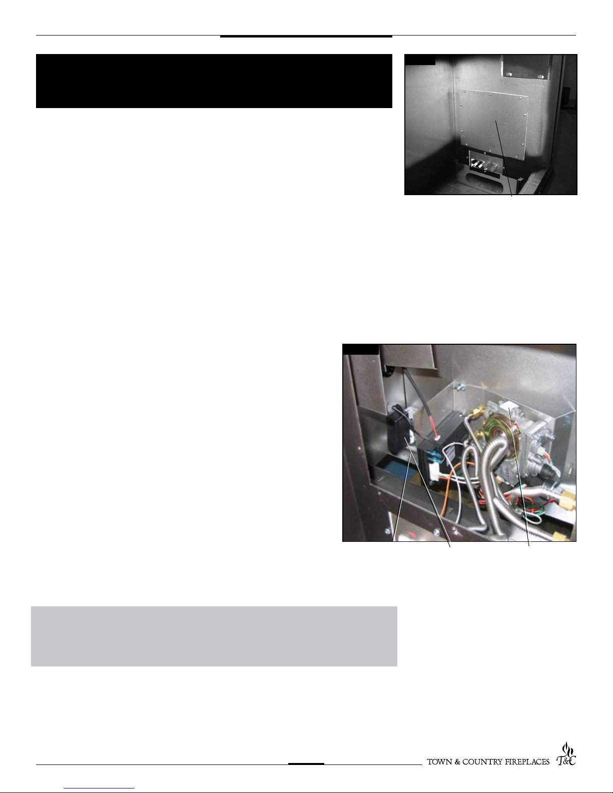
Installation
1. Place the replace in the desired location.
2. Remove the window from the replace.
3. Remove access panel from right hand side of the rebox (Fig. #16)
NOTE: The ex lines may have to be pushed down to allow the shield to be lowered
enough to clear the top tab.
4. Connect a 110 V. AC electrical supply to the outlet installed inside the control box. The
supply should be wired to the latest version of National codes (CSA C22.1-ANSI/NFPA
70) and or local codes. (Fig. #17)
5. Connect the gas supply to the valve (Fig. #17)
Fig. #17
ACCESS PANEL
6. Plug the A/C adaptor into the outlet (Fig. #17)
7. Attach the electrical box for the supplied wall control to the framing in the desired
location (up to 50 ft. away). (25 ft. is supplied with replace. An additional 25 ft. can
be achieved by using the optional kit (Part # 5005.064) available from your
dealer).
WARNING: The access panel including gasket must be reinstalled
after conversion/ installation or servicing has been completed. Failure
to do so will cause overheating and premature failure of the control
system.
TCWS.38CE 300709-44
13
OUTLET
ADAPTER
GAS CONNECTION
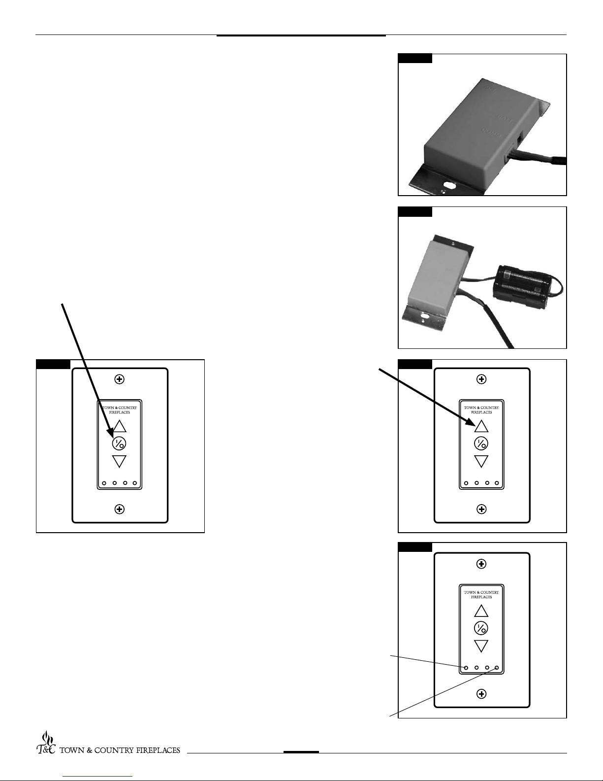
8. Route the communication cable as required to the wall control electrical box.
9. Attach the communication cable to the wall control. (Fig. #18)
10. Insert the 4 supplied “AA” batteries into the battery pack and connect to wall control.
(Fig. #19)
11. Fasten the wall switch to the electrical box.
12. Fasten the faceplate to switch
13. If not already installed, install the burner using the instructions supplied
with the burner kit.
14. Turn on the gas supply and check that all connections are tight and leak free.
15. Turn on electrical supply.
16. Press the center button on the wall control (Fig. #20). The igniter will start to spark.
After a short delay the pilot will light, followed by the main burner.
17. Press the up button (Fig.21) on the wall
control and hold it for 5 seconds or
until a clicking sound is heard from the
gas control. Release the button, check
Fig. #20
manifold pressure and ensure that it’s
correct.
(Refer to Burner installation manual)
Fig. #18
Fig. #19
Fig. #21
18. Press the center button of the wall control.
The replace will shut off.
19. Install the remaining screws in the access
panel and tighten.
20. Remove the pressure gauge and the
extension test tting and thread the plug
into the pressure test port. Thread sealant is required on the threads. (Refer to
Burner installation manual)
21. Turn the replace on.
Standing Pilot Function
(Only for use where permitted)
The control system on this replace is set to operate as electronic ignition. If required the
system can be converted to a standing pilot by depressing a recessed button located on the
lower right hand side of the wall control. (Fig. #22) This should be depressed with a paperclip,
pencil or other thin object. Once activated the pilot will run continuously. Please check with
your local inspector to ensure that this is permitted in your area.
LEARN BUTTON
Fig. #22
STANDING PILOT BUTTON
TCWS.38CE 300709-44
14
 Loading...