

Town & Country Fireplaces TCVT.WSPVB1 Installation And Operating Instructions Manual

IMPORTANT:
THESE INSTRUCTIONS ARE TO REMAIN
WITH THE APPLIANCE INSTRUCTIONS
These instructions are supplementary to the Installation and
Operating Instructions supplied with the replace and should
be kept together. Refer to the Installation and Operating
Instructions for proper gas supply, safety requirements and
operating instructions
OPTIONAL
VERTICAL OR
HORIZONTAL
POWER VENT KIT
Power Vent Terminal
(TCVT.502461)
5 x 8 Pipe
(Simpson Duravent)
(Secure Vent)
(Selkirk Direct-temp)
NOT SUPPLIED
Vent Adaptor
(5096.814)
TCVT.WSPVB1
INSTALLATION AND
OPERATING
INSTRUCTIONS
Simpson
Duravent #1247
wall thimble
NOT SUPPLIED
091009-12 TCVT.WSPVB1 5056.425213
Power Vent Installation
Locate the replace as per the main instructions supplied.
Make the following modications to add the components used with the Power Vent Kits. This Kit can only be used in
conjunction with the Town and Country WS replaces. This installation must conform with local codes or, in the absence
of local codes, with the Natural Fuel Gas Code, ANSI Z223.1/NFPA 54, or the Natural Gas and Propane Installation Code,
CSA B149.1. This appliance must be electrically grounded in accordance with local codes or, in the absence of local
codes, with the National Electrical Code, ANSI/NFPA 70, or the Canadian Electrical code, CSA C22.1.
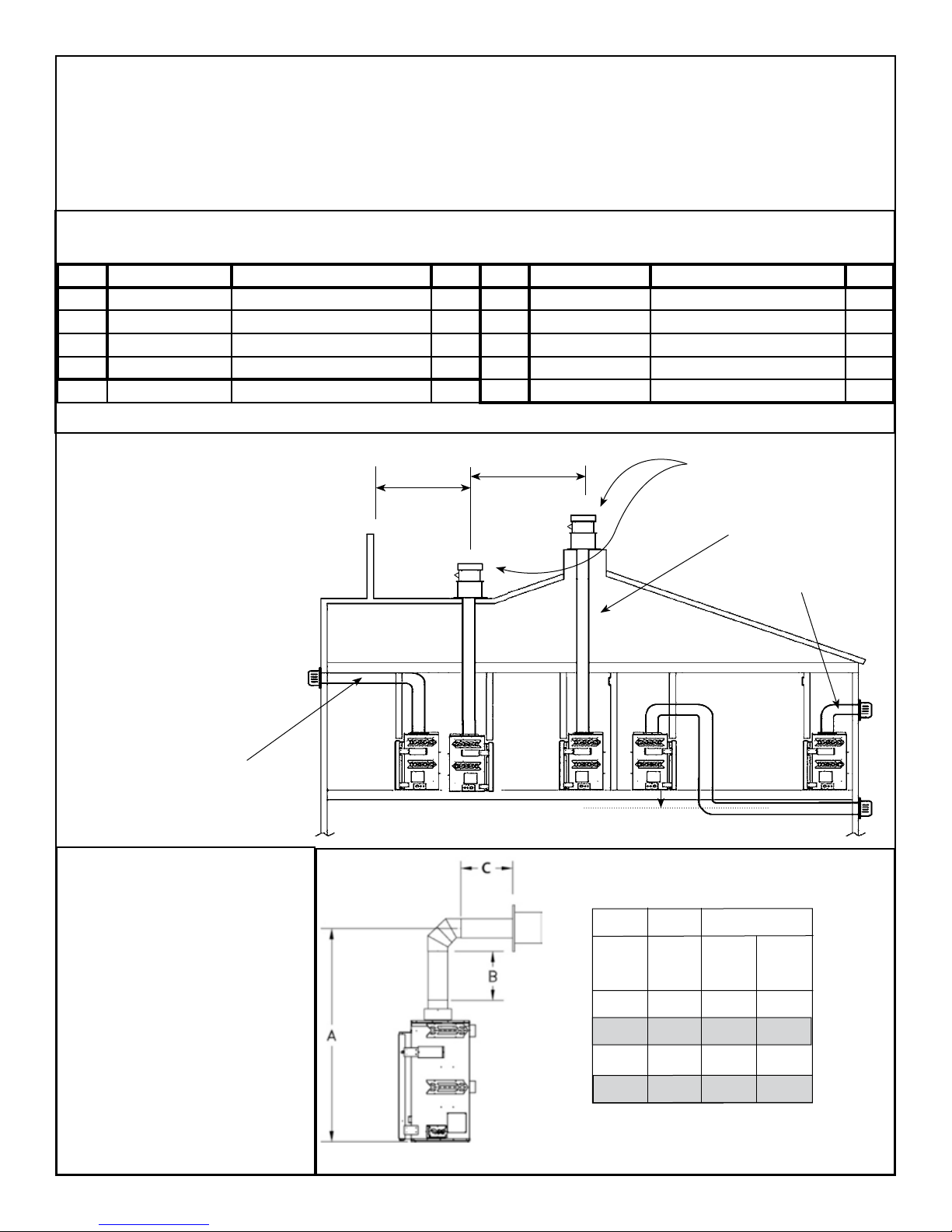
Contents of Power Vent Kit
ITEM PART No. DESCRIPTION QTY. ITEM PART No. DESCRIPTION QTY.
1 TCVT.502461 Power Vent Terminal 1 5 5027.15 Pressure Switch 1
2 5096.814 Venting Adaptor 1 6 8240 Tubing, TYSC-516316-100 1
3 TCVT.50271C2 Pressure Switch Wiring 1 7 Hose Clamp 1
4 8271 Pressure Switch Bracket 1 8 5093.02 Hose Clamp 1
9 TCVT.507156C PV Module Switch Wire 1
Fig. #1
VENTING CONFIGURATIONS
Maximum vent length is 110 ft
plus six 90-degree elbows or
combination of other elbows
equaling 90-degrees, with a
maximum 66 foot vertical rise.
Minimum vent length is 4 ft
plus one 90-degree elbow.
The vent can be installed
with any combination of rise
and run between the gures
including up to 3 ft below
the unit. Ensure vent pipe is
properly supported.
Maximum combined
vertical & horizontal
venting 110 ft plus six
90-degree elbows.
MINIMUM CLEARANCES TO
COMBUSTIBLE
4 ft min.
Vertical Application must use TCVT.PVVCA Box in
conjunction with this kit
6 ft min.
Maximum
vertical of 66 ft
Min. venting - 4 ft plus
one 90-degree elbow
3 ft below unit (Max) to
centerline of vent pipe
WALL TERMINATION VENTING CHART
Vertical vent pipe:
1.5 in. (38mm)
Horizontal vent pipe:
Top 1.5 in. (38mm)
Sides 1.5 in. (38mm)
Bottom 1.5 in. (38mm)
All other clearances are as
per the replace installation
instructions.
2 TCVT.WSPVB1 091009-12
Fig. #1a
A B C
Min.
Rise
49” 0” 110 feet 4 feet
57” 12” 109 feet 3 feet
65” 24” 108 feet 2 foot
Pipe
Length
Max Pipe
Length
Min Pipe
Length
M
K
I
A
V
G
G
H
A
J
V
G
A
B
C
A
V
V
A
V
B
F
B
L
V
E
V
V
V
D
B
B
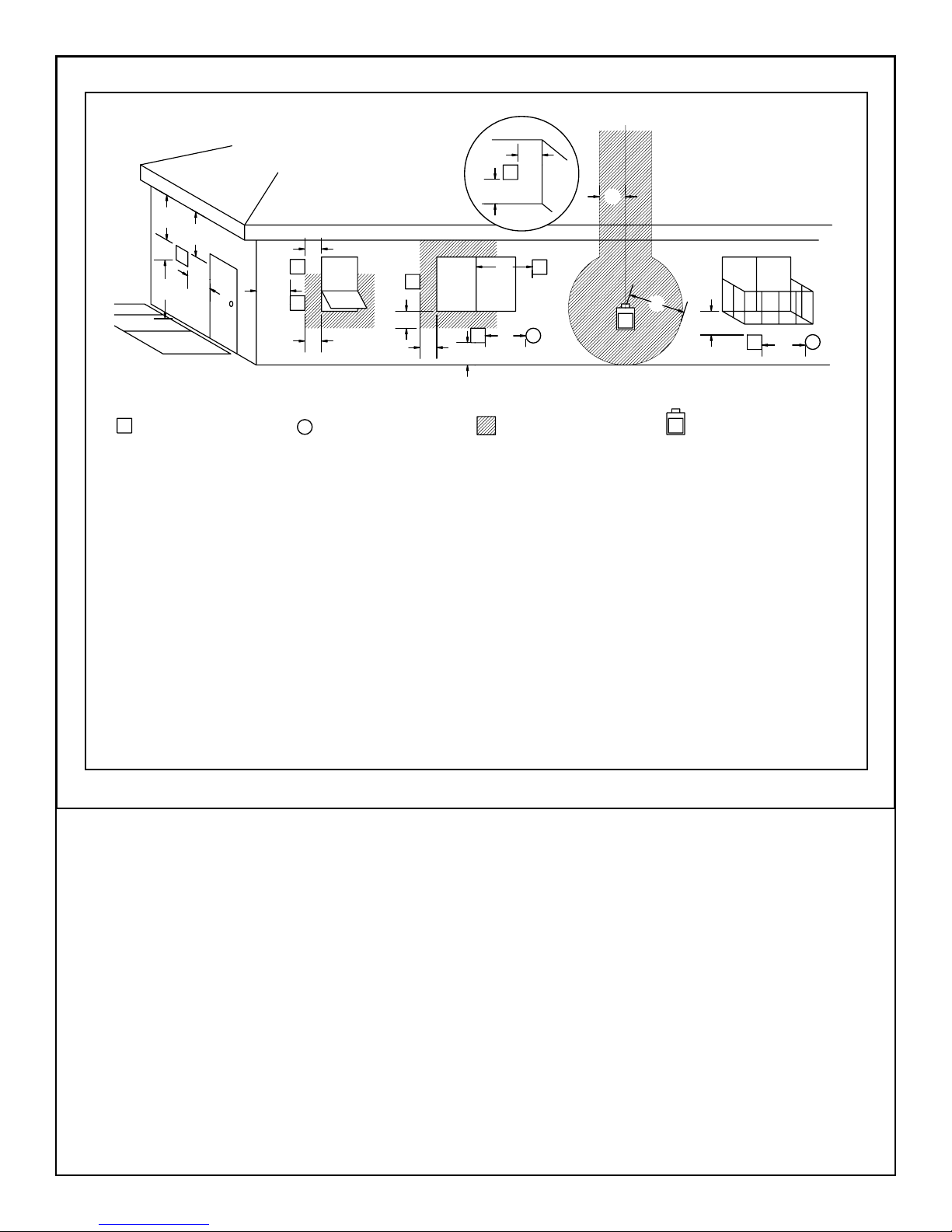
Fig. # 2
FIXED
CLOSED
OPEN ABLE
INSIDE
CORNER
DETAIL
OPENABLE
FIXED
CLOSED
VENT TERMINAL MINIMUM
CLEARANCES
VENT TERMINAL GAS METER
AIR SUPPLY INLET
A= clearances above grade, veranda, porch, deck, or balcony [*
12 inches (30 cm) minimum]
B= clearance to window or door that may be opened [* 12
inches (30 cm) minimum]
C= clearance to permanently closed window [minimum 12
inches (30 cm) recommended to prevent condensation on
window]
D= vertical clearance to ventilated soffit located above the ter-
minal within a horizontal distance of 2 feet (60 cm) from the
edge of the terminal [12 inches (30 cm) minimum]
E= clearance to unventilated soffit [12 inches (30 cm) minimum]
F= clearance to outside corner [6 inches (15 cm) minimum]
G= clearance to inside corner [6 inches (15 cm) minimum]
AREA WHERE TERMINAL
IS NOT PERMITTED
H= * not to be installed above a meter/regulator assembly within
3 feet (90 cm) horizontally from the center-line of the regulator
I= clearance to service regulator vent outlet [* 6 feet (1.8 m)
minimum]
J= clearance to nonmechanical air supply inlet to building or
the combustion air inlet to any other appliance [* 12 inches
(30 cm) minimum]
K= clearance to a mechanical air supply inlet [* 6 feet (1.8 m)
minimum]
L= ^ clearance above paved side-walk or a paved driveway
located on public property [* 7 feet (2.1 m) minimum]
M= clearance under veranda, porch, deck, or balcony
[12 inches (30 cm) minimum**]
^ a vent shall not terminate directly above a side-walk or paved driveway which is located between two single family dwellings and
serves both dwellings*
** only permitted if veranda, porch, deck, or balcony is fully open on a minimum of 2 sides beneath the oor*
* as specied in CGA B149 Installation Codes, Note: local Codes or Regulation may require different clearances
* for U.S.A. Installations follow the current National Fuel Gas Code, ANSI Z223.1
091009-12 TCVT.WSPVB1 3
Horizontal (Side wall) Venting
This kit uses either Simpson Duravent GS direct vent pipe, Secure Vent direct vent pipe or Selkirk Direct-temp
vent pipe with a 5” inner pipe and an 8” outer pipe. For part numbers see the table of venting components on
page 11 of this manual.
1. Locate the power vent termination following the clearance
to combustible table, venting conguration diagram (Fig. #1 &
1a), and terminal location diagram (Fig. #2).
2. Cut and frame an 11” x 11” opening. The centre of
the square hole should line up with the centre line of the
horizontal pipe.
3. Install the Simpson Duravent (or equivalent) Wall thimble,
part number 1247 (not supplied with kit) in the opening
to retain any insulation in the wall and maintain proper
clearances. If the wall being penetrated is constructed of
noncombustible material only (i.e.. Masonry block or concrete)
the wall thimble is not required and a hole with zero clearance
is acceptable. (8” hole)
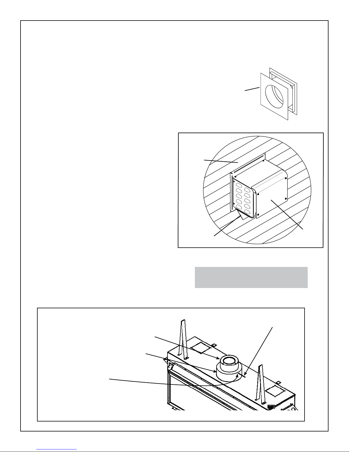
4. Attach the terminal to the outside wall. Ensure that the
terminal is the right way up and that only the outer anges that
are used to secure the terminal to the building are covered by
the exterior wall or siding. (Fig.#3) Note: No other part of the
terminal can be recessed into the exterior wall or siding.
Fig.#3
Finished
Wall
Wall Thimble
(Not Supplied)
5. Attach the vent adaptor directly to the appliance with three
screws. Note: The inner pipe does not need to be sealed.
(Fig. #4)
6. Connect the high temperature silicone tube to the pressure
tap on the adaptor, secure with the hose clamp provided and
route the tube through any hole back to control box. (Fig.
#4) Tube may touch unit and be trimmed if required. Note:
Ensure that there are no blockages in this tube, as this
will cause the control to malfunction.
7. Run the required Simpson Duravent GS / Secure Vent
/ Selkirk Direct-temp pipe from the adaptor to the terminal
assembly. Assemble as per the vent pipe manufacturer’s
instructions.
Fig.#4
Power Vent Adaptor. Part # 5096.814
MUST BE INSTALLED AT THE UNIT
Secure with three screws
Blower
Outlet
CAUTION: The vent restrictor must be fully
open for proper operation.
PRESSURE
TAP
Power Vent
Terminal
Seal not required
4 TCVT.WSPVB1 091009-12
 Loading...