

Town & Country Fireplaces TCVT.PVCV Installation And Operating Instructions Manual
IMPORTANT:
THESE INSTRUCTIONS ARE TO REMAIN
WITH THE HOMEOWNER
These instructions are supplementary to the Installation and
Operating Instructions supplied with the fireplace and should
be kept together. Refer to the Installation and Operating
Instructions for proper gas supply, safety requirements and
operating instructions.
VERTICAL
POWER VENT KIT
310317-20
TCVT.PVCV
INSTALLATION AND
OPERATING
INSTRUCTIONS
Visit www. townandcountryfireplaces.net for the most recent version of this manual
TCVT.PVCV
5056.42665-A
Power Vent Installation
Locate the replace as per the main instructions supplied. Make the following modications to add the components used with the Power Vent kits. This kit can only be used in conjunction with the “B”, “C” & “D” series
versions of Town and Country Fireplaces. This installation must conform with local codes or, in the absence
of local codes, with the Natural Fuel Gas Code, ANSI Z223.1/NFPA 54, or the Natural Gas and Propane
Installation Code, CSA B149.1.
All electrical installation should be performed by a qualied electrician to national codes (CSA C22.1, ANSI/
NFPA 70) and/or local electrical codes.
under no circumstances shall a rheostat be used to alter the voltage supply to this unit.
Contents of Power Vent Kit
ITEM PART No. DESCRIPTION QTY
1 TCVT.502462 Power Vent Terminal 1
2 TCVT-8074 Vertical Rain Cap 1
3 TCVT-8075 Vertical Standoff 1
4 8082.001 Flashing 1
5 8085 Drip Shield 1
Note: The adapter kit TCVT.PVKIT is required for all units except the TCWS.54CSTE.
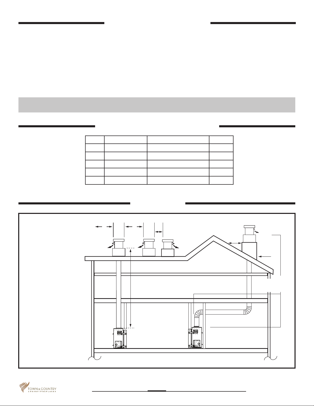
VENTING
CONFIGURATIONS
Maximum vent length is
110 ft plus six 90-degree
elbows or combination
of other elbows equaling 90-degrees, with a
maximum 66 foot vertical rise.
Minimum vent length is
3 ft plus one 90-degree
elbow. The vent can
be installed with any
combination of rise and
run between the gures including up to 3 ft
below the unit. Ensure
vent pipe is properly
supported.
Power Vent
4’ 4’
Max 66’
vertical rise
1’
Distance
as per
local
code
Total maximum
vent length is 110’
Vent outlet
direction
Site
fabricated
chase
66’ maximum
vertical rise
Figure 1: Power vent congurations.
5056.42665-A
310317-20 TCVT.PVCV
2

Minimum Clearances to Combustibles
Vertical vent pipe: 1.5 in. (38mm)
Horizontal vent pipe: Top 1.5 in. (38mm)
Sides 1.5 in. (38mm)
Bottom 1.5 in. (38mm)
All other clearances are as per the replace installation instructions.
Vertical (Through Roof) Venting
VENT PIPE
This kit uses either Simpson Duravent GS direct vent pipe, Secure Vent direct vent pipe, Selkirk Direct-temp
vent pipe or ICC Excel Direct vent pipe with a 5” inner pipe and an 8” outer pipe. For part numbers see the
table of venting components on page 10 of this manual.
CAUTION: The adjustable vent restrictor located on the underside of the firebox top must be fully open.
The vertical standoff can only be installed on a at surface. Sloped surfaces require the construction of a
chase which provides the minimum interior, square opening of 11” x 11” for the venting and wiring to pass
through. Flat roofs may require a chase depending on local codes and roof construction. (If in doubt check
with local inspector). The terminal must be located in accordance with the clearances outlined in Figure 1.
Installation:
All part numbers in the following section are shown in Figure 3.
1. Place the ashing onto the chase and seal using silicone.
2. Put a bead of silicone on the underside of the vertical standoff and place it on top of the ashing. Align the
eight holes and secure both parts to the chase using eight #8 x 1 1/2” screws provided.
3. Install the drip shield onto the top of the vertical standoff using a bead of silicone between the two. Do not
screw this part in place.
4. Bring the 14-2 electrical wire (not supplied) up through the holes in both the ashing and the drip shield
leaving at least 12” of excess wire above the drip shield.
5. IMPORTANT: Attach an appropriate length(s) of the vent to the power vent terminal, sufcient to pass
through the chase.
NOTE: DO NOT CONNECT AN ADJUSTABLE LENGTH VENT PIPE TO THE TERMINAL.
6. Seal the connection of the rst length of pipe at the terminal and any other pipe to pipe joint by both
screwing and taping the outside joint using high temperature foil tape.
7. Remove the junction box cover.
8. Remove and discard the exhaust outlet.
310317-20 TCVT.PVCV
5056.42665-A
3
9. Apply a bead of silicone on the bottom ange of the power vent terminal.
10. Slide the vent through the drip shield and at the same time thread the electrical lead through the hole in
the bottom of the terminal.
11. With the power vent terminal resting on the drip shield, align the eight holes in each of the vertical standoff, the drip shield and the power vent terminal and then screw them together using the eight #8 x 1/2”
stainless screws provided.
12. Join the 14-2 wire lead to the blower wires using the appropriate connectors and attach the ground wire.
Reinstall the junction box cover.
13. Install the vertical rain cap over the power vent blower. ALIGN THE EXHAUST OUTLET ON THE POWER
VENT TERMINAL WITH THE EXHAUST PORT ON THE VERTICAL RAIN CAP.
14. Secure the vertical rain cap to the power vent blower with the remaining eight #8 x 1/2” stainless screws.
NOTE:THERE ARE NO PILOT HOLES IN THE BASE OF THE POWER VENT TERMINAL. 1/8” DIAMETER
PILOT HOLES SHOULD BE DRILLED USING THE HOLES IN THE VERTICAL RAIN CAP AS A GUIDE.
DO NOT SILICONE THE VERTICAL RAIN CAP TO THE POWER VENT TERMINAL AS IT NEEDS TO BE
REMOVABLE FOR SERVICING.
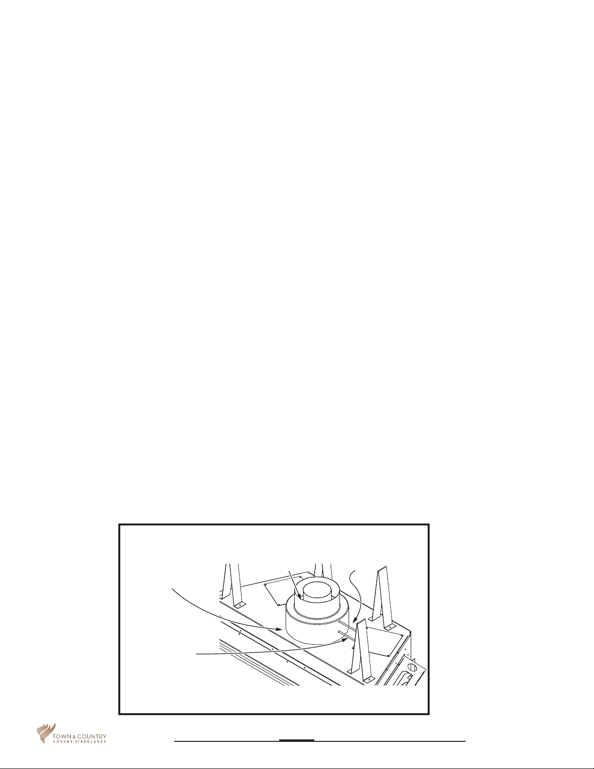
15. Attach the vent adaptor directly to the appliance with three screws (Figure 2).
Note: The inner pipe does not need to be sealed.
16. Connect one of the high temperature silicone tubes to the upper pressure tap on the adaptor (Figure
2) Secure with the hose clamp provided and route the tube through any hole back to control box. This
tube will be connected to the “low” side of the vacuum switch inside the control compartment (Figure 9).
Connect the second tube to the lower pressure tap and route to the control box as before. Connect this
tube to the remaining port on the vacuum switch. Tubes may touch unit and be trimmed if required. Note:
Ensure that there are no blockages in these tubes, as this will cause the control to malfunction.
17. Run the required Simpson Duravent GS / Secure Vent / Selkirk Direct-temp pipe from the adaptor to the
terminal assembly. Assemble as per the vent pipe manufacturer’s instructions including all shields and
restops.
Secure with 3 screws and
seal with aluminum tape
Power Vent Adaptor.
Must be installed
at the unit
*
Upper pressure
tap, marked
“LOW”
Figure 2: Power vent adapter.
Lower pressure tap,
marked “HIGH”
*
5056.42665-A
Power vent adapter not required on models
TCWS.54DST and TCWS.54STOK.
310317-20 TCVT.PVCV
4
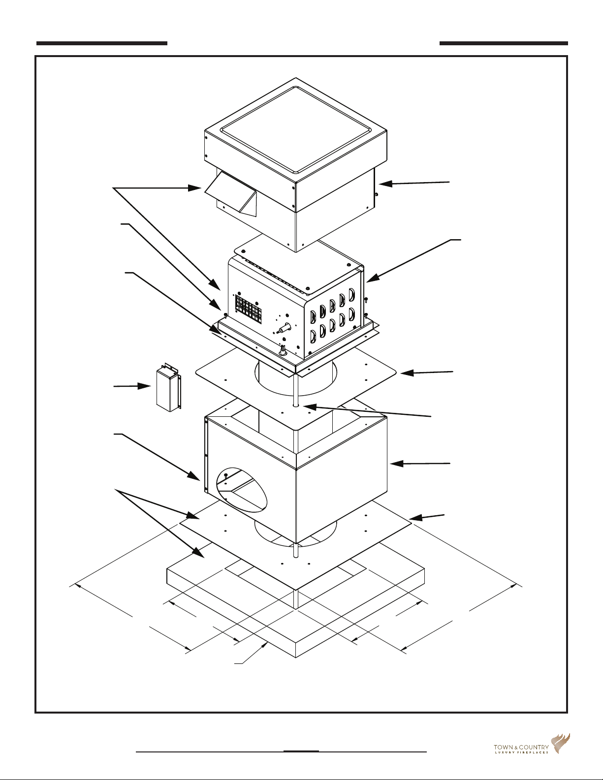
Vertical (Through Roof) Venting
MUST ALIGN
#8 x 1/2" S.S.
(16 Required)
NOTE: Holes to
secure rain cap
are
not predrilled
Junction box
cover
#8 x 1-1/2" S.S.
(8 Required)
Vertical Rain Cap
TCVT-8074
Power Vent
TCVT.502462
Drip Shield
14-2 Wire w/ Ground
Vertical Standoff
TCVT-8075
8085
Silicone all
connecting faces
18”
Site Fabricated Chase
Final Installation Height: 21"
Figure 3: Power vent components.
310317-20 TCVT.PVCV
11”
Flashing 8082.001
11”
18”
5056.42665-A
5
Control System Connection
For “Series C” Fireplaces
The gas control system is located on the right hand side of the rebox behind an access panel and the decorative panel.
1. Remove burner assembly, burner media and decorative panels if already installed (see main installation
manual for details).
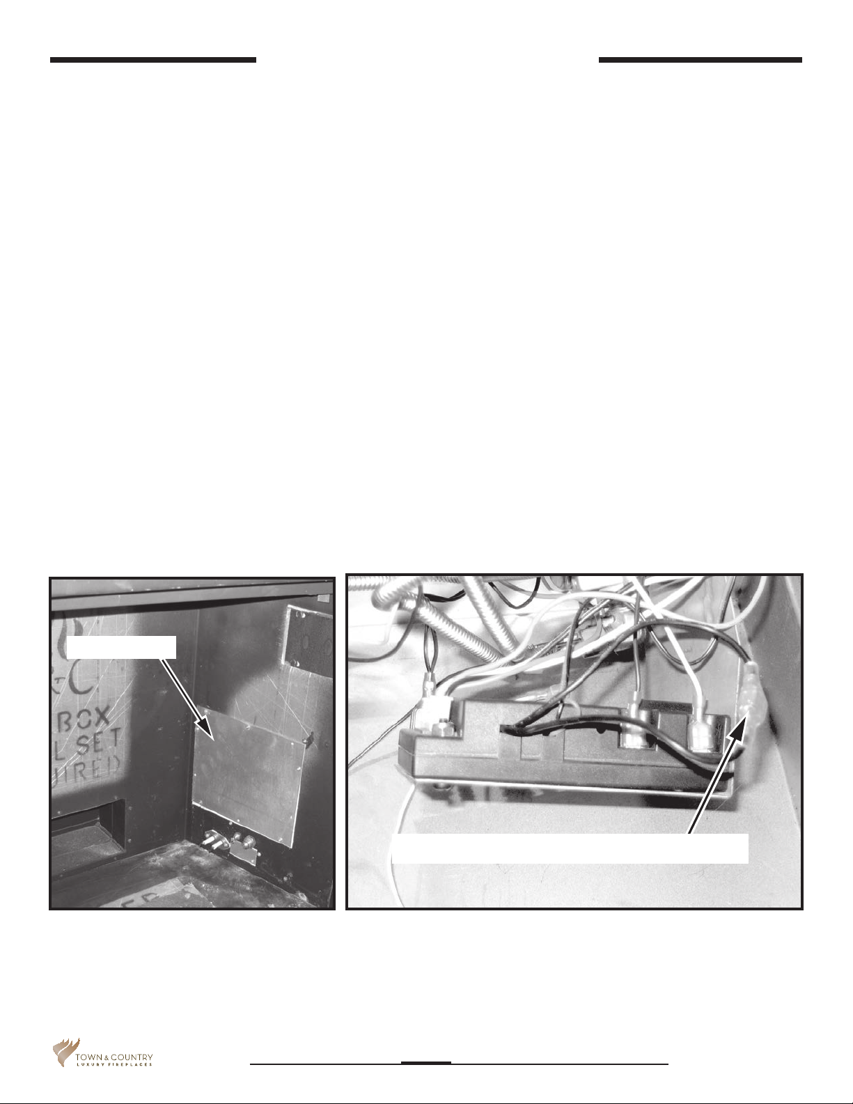
2. Remove access panel from right hand side of the rebox (Figure 4).
3. Locate and disconnect the spade connectors in the black wire loop on the right side of the module and in
the orange wire running from the module to the socket labelled “pilot”on the valve (Figure 5 and Figure 6).
4. Using the jumper wires provided, connect the 120V “hot” supply wire to one of the black wires from the
control module. Then connect the “hot” wire from the power vent blower to the other black wire on the
control module (Figure 7). The module acts as a switch to turn on the power vent blower. (Also see wiring
diagram on Pg.14)
Access panel
Figure 4: Access panel.
Spade connector in black wire loop
Figure 5: Locating black wire spade connector.
5056.42665-A
310317-20 TCVT.PVCV
6
 Loading...