

Town & Country Fireplaces TCVT.FMPV3 Installation And Operating Instructions Manual

IMPORTANT:
THESE INSTRUCTIONS ARE TO REMAIN
WITH THE HOMEOWNER
These instructions are supplementary to the Installation
and Operating Instructions supplied with the replace
and should be kept together. Refer to the Installation
and Operating Instructions for proper gas supply, safety
requirements and operating instructions.
LOW NOISE
HORIZONTAL FLUSH
MOUNT POWER
VENT KIT
(FOR MAXIMUM 6’ HORIZONTAL RUNS)
Flush Mount Power
Vent Assy.
For use with
any TC Series
“C” unit,
except TC54.
Wall Sleeve
Assembly
Inner Wall Plate
Wall Pipe Cover
Vent Adaptor
111011-16 TCVT.FMPV3 5056.4265C3
TCVT.FMPV3
INSTALLATION AND
OPERATING
INSTRUCTIONS
PAINT:
Power Vent Installation
The vent terminal comes pre-painted
with Thurmalox 230 Series paint by
Dampney Co., but can be painted
to match your wall nish color
using high temperature paint that
can withstand temperatures of at
least 250 degrees Fahrenheit or 120
degrees Celcius.
Ensure the your paint is compatible
with Thurmalox 230 Series paint.
MINIMUM CLEARANCES TO
COMBUSTIBLE
Terminal casing:
0in. (0mm)
Vertical vent pipe:
1.5 in. (38mm)
Horizontal vent pipe:
1.5 in. (38mm)
All other clearances are as per the replace
installation instructions.
Locate the replace as per the main instructions supplied.
Make the following modi cations to add the components used with the Flush
Mount Power Vent Kits. This Kit can only be used in conjunction with the “C” series
versions of Town and Country replaces, except the TC54.CE2. This installation
must conform with local codes or, in the absence of local codes, with the National
Fuel Gas Code, ANSI Z223.1/NFPA 54, or the Natural Gas and Propane Installation
Code, CSA B149.1.
All electrical installations should be performed by a quali ed electrician to the
Canadian and U.S. National Electrical Codes (CSA C22.1 for Canada), (ANSI/NFPA
70 for the U.S.) and/or local electrical codes.
Contents of Power Vent Kit
ITEM PART No. DESCRIPTION QTY
1 TCVT.8043 Flush Mount Power Vent Assy. 1
2 5096.816 Venting Adaptor 1
3 TCVT.506271C Pressure Switch Wiring 1
4 5027.15 Pressure Switch 1
5 8024 Tubing, TYSC-516316-100 2
6 5093.01 Hose Clamp 2
7 5093.02 Hose Clamp 2
8 TCVT.507156C Power Vent Switch Wire 1
9 8271 TCWS.54CE2 Pressure Switch Bracket 1
10 9280 TC Pressure Switch Bracket 1
Fig. #1
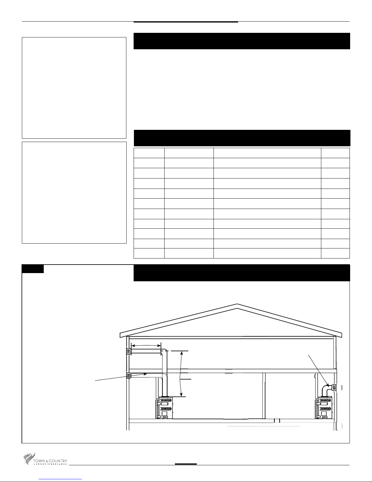
VENTING CONFIGURATIONS
Maximum total horizontal vent
length is 6ft. Minimum total
vent length is 3 ft plus one
90-degree elbow. Ensure vent
pipe is properly supported.
For every 90-degree elbow
after the rst transition,
subtract 2’ from max.
horizontal run.
Min. 1 1/2” Clearance to
combustible surfaces from
vent pipe.
Power Vent
MAX. 6’
Min. venting - 3 ft plus
one 90-degree elbow
66’ MAX. VERTICAL
111011-16 TCVT.FMPV3
2
Minimum Vent Length Chart
Fig. #2
Minimum Rise Pipe Min.
From Floor to Flue Center Length Pipe
Length
TCWS54 TCWS38 TC30 TC36* TC 42 TC36ST
49” 45” 47” 51” 57” 56” 0” 3 feet
61” 57” 59” 63” 69” 68” 12” 2 feet
73” 69” 71” 75” 81” 80” 24” 1 foot
*TC36 and TC36AR have the same dimensions
This power vent kit cannot be used on model TC54.CE2
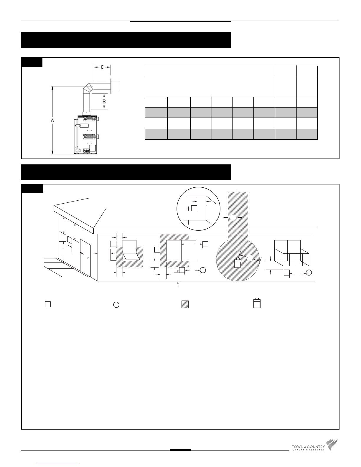
Vent Terminal Minimum Clearances
Fig. #3
A B C
INSIDE
CORNER
DETAIL
D
E
V
B
L
VENT TERMINAL GAS METER
V
C
FIXED
V
CLOSED
F
OPEN ABLE
V
B
AIR SUPPLY INLET
A
OPEN-
V
ABLE
B
B
V
A
A= clearances above grade, veranda, porch, deck, or balcony [*
12 inches (30 cm) minimum]
B= clearance to window or door that may be opened [* 12
inches (30 cm) minimum]
C= clearance to permanently closed window [minimum 12
inches (30 cm) recommended to prevent condensation on
window]
D= vertical clearance to ventilated soffit located above the ter-
minal within a horizontal distance of 2 feet (60 cm) from the
edge of the terminal [0 inches (0 cm) minimum]
E= clearance to unventilated soffit [0 inches (0 cm) minimum]
F= clearance to outside corner [6 inches (15 cm) minimum]
G= clearance to inside corner [3 inches (7.5 cm) minimum]
G
V
A
V
B
FIXED
CLOSED
A
J
AREA WHERE TERMINAL
IS NOT PERMITTED
H
I
G
M
V
K
G
H= * not to be installed above a meter/regulator assembly within
3 feet (90 cm) horizontally from the center-line of the regulator
I= clearance to service regulator vent outlet [* 6 feet (1.8 m)
minimum]
J= clearance to nonmechanical air supply inlet to building or the
combustion air inlet to any other appliance [* 12 inches (30
cm) minimum]
K= clearance to a mechanical air supply inlet [* 6 feet (1.8 m)
minimum]
L= ^ clearance above paved side-walk or a paved driveway
located on public property [* 7 feet (2.1 m) minimum]
M= clearance under veranda, porch, deck, or balcony
A
[0 inches (0 cm) minimum**]
^ a vent shall not terminate directly above a side-walk or paved driveway which is located between two single family dwellings and
serves both dwellings*
** only permitted if veranda, porch, deck, or balcony is fully open on a minimum of 2 sides beneath the oor*
* as speci ed in CGA B149 Installation Codes, Note: local Codes or Regulation may require different clearances
* for U.S.A. Installations follow the current National Fuel Gas Code, ANSI Z223.1
111011-16 TCVT.FMPV3
3
CAUTION:
This terminal is designed to be
nished ush to the nished outside
wall; under no circumstances
should this terminal be recessed
into the wall past this point.
(Fig. #8)
Horizontal (Side Wall) Venting
This kit uses either Simpson Duravent GS direct vent pipe, Secure Vent
direct vent pipe, Selkirk Direct-temp vent pipe or ICC Exceldirect vent pipe
with a 5” inner pipe and an 8” outer pipe. For part numbers see the table of
venting components on page 10 of this manual. This vent can only be used
as a side wall termination.
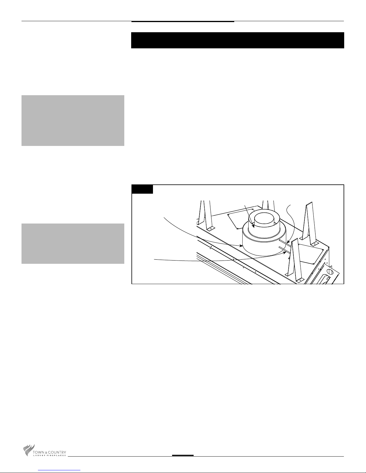
1. Attach the vent adaptor directly to the appliance with the three screws and seal outer
pipe with aluminium tape provided. (Fig. #4)
Note: The inner pipe does not need to be sealed.
2. Connect one of the high temperature silicone tubes to the upper pressure tap(marked
“LOW”) on the adaptor.(Fig.#4) Secure with the hose clamp provided and route the tube
through any hole back to the control box. This tube will be connected to the “low” side of
the pressure switch inside the control compartment.(Fig.#17) Connect the second tube to
the lower pressure tap(marked “HIGH”) and route to the control box as before. Connect this
tube to the remaining port on the pressure switch.
Tubes may touch unit and be trimmed if required.
Note: Ensure that there are no blockages in these tubes, as this will cause the
control to malfunction.
CAUTION:
The adjustable vent restrictor located
on the underside of the rebox top
must be fully open.
Fig. #4
SECURE WITH
THREE SCREWS
AND SEAL WITH
TAPE
.
LOWER PRESSURE
TAP, MARKED
“HIGH”
3. Locate the power vent termination following the clearance to combustible table(Page 2),
venting con guration diagram (Fig. #1 & 2), and terminal location diagram (Fig. #3).
4. Cut and frame a 14 1/2” wide by 14 3/4” high opening. For standard up and out
installations, the opening should be 3/4” lower than the minimum speci ed in Fig. #2.
Height of the opening will vary with each installation. See Fig. #5.
5. Attach the power vent terminal, by securing the outer anges on the perimeter of the
terminal to the outside wall; ensure that the terminal is the right way up (exhaust at the
bottom). Once secured to the building, the outer anges may be covered with siding/
stucco/etc. up to the level of the perimeter edge. As per local building codes. See Fig. #6.
Power Vent Adaptor.
Part # 5096.816
MUST BE INSTALLED
AT THE UNIT.
UPPER PRESSURE
TAP, MARKED
“LOW”
6. For wall thicknesses 7 1/2” or less, install the inner wall plate supplied over the terminal
as shown in Fig. #6 and secure to the framing. See Fig. #7.
111011-16 TCVT.FMPV3
4
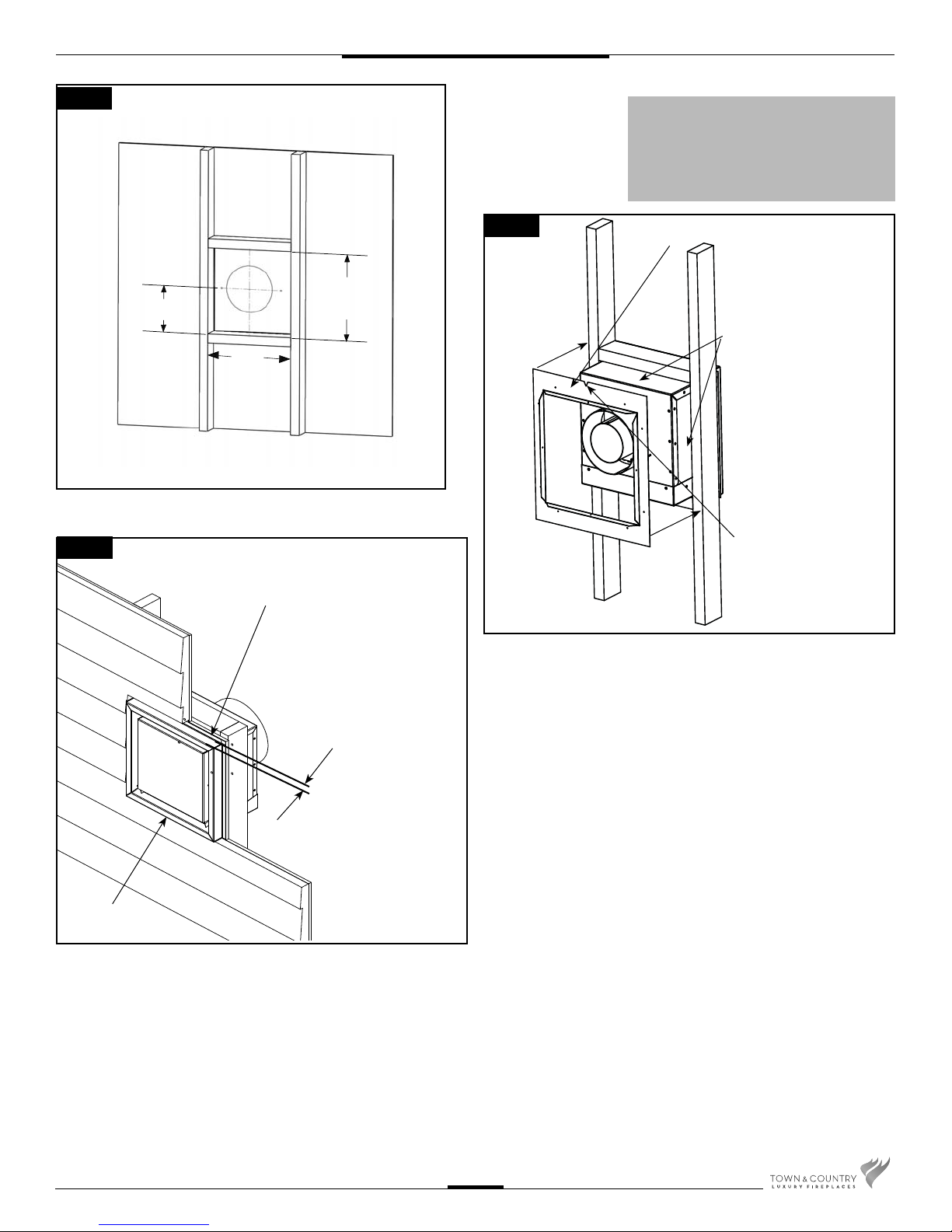
Fig. #5
CAUTION:
The rise and run combination and the
number of elbows must not exceed
speci cations in Fig #1 and Fig #2.
Fig. #6
7 7/8”
14 3/4”
14 1/2”
TERMINAL SECURING
FLANGE
Fig. #7
INNER WALL PLATE
SEAL WITH SILICONE
ON ALL FOUR SIDES
NOTCH AT THE TOP
WALL FINISH NO
DEEPER THAN 1 1/4”
EXHAUST
111011-16 TCVT.FMPV3
5
 Loading...