

Town & Country Fireplaces TC54.NG04C2 Instructions Manual

IMPORTANT:
THESE INSTRUCTIONS ARE TO REMAIN
WITH THE HOMEOWNER
These instructions are supplementary to the Installation
and Operating Instructions supplied with the replace
and should be kept together. Refer to the Installation
and Operating Instructions for proper gas supply, safety
requirements and operating instructions.
TC54
TRANQUILITY
BURNER KIT
INSTRUCTIONS
070211-16 TC54.NG04C2 5056.4256204
PART# TC54.NG04C2
For TC54 Series C
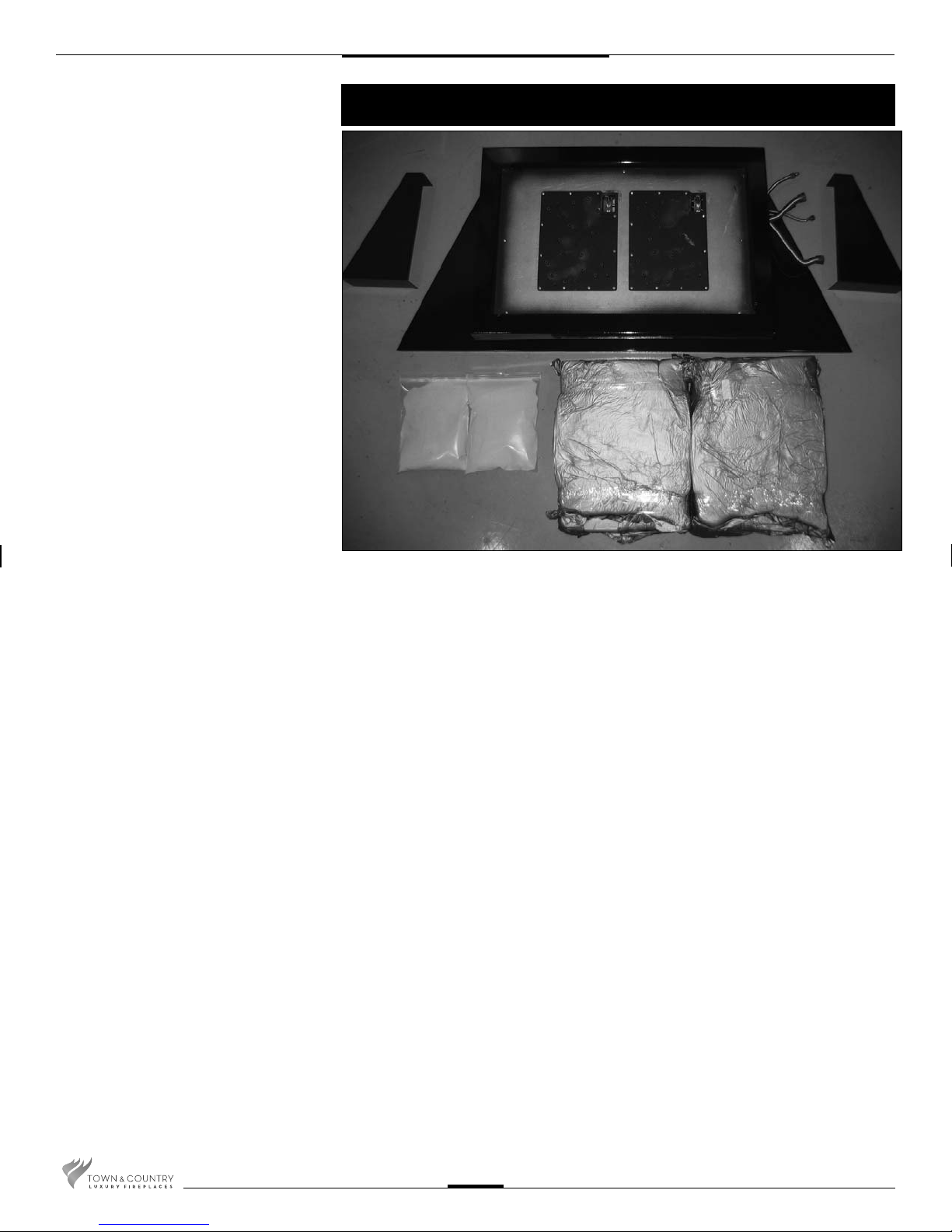
Contents of Package
K
D
C
A BURNER ASSEMBLY
B PEBBLE ASSEMBLY
C 7lbs SAND
D LINE COVER, LEFT
E LINE COVER, RIGHT
F PKG. TAPERED PLUGS (not shown)
E
A
B
TC54.NGO4C2 070211-16
2
Tranquility Burner Installation
A panel set must be used in conjunction with the installation of the burner assembly.
See Installation and Operating Instructions manual for details.
Typically all panels except the right side should be installed prior to burner
*
installation.
NOTE: Due to the size of this unit it is highly recommended that two persons be
available during installation.
NOTE: Plug the 4 vacant holes in the bottom of the rebox with 1/2” screws,
as they are not required to attach this style of burner.
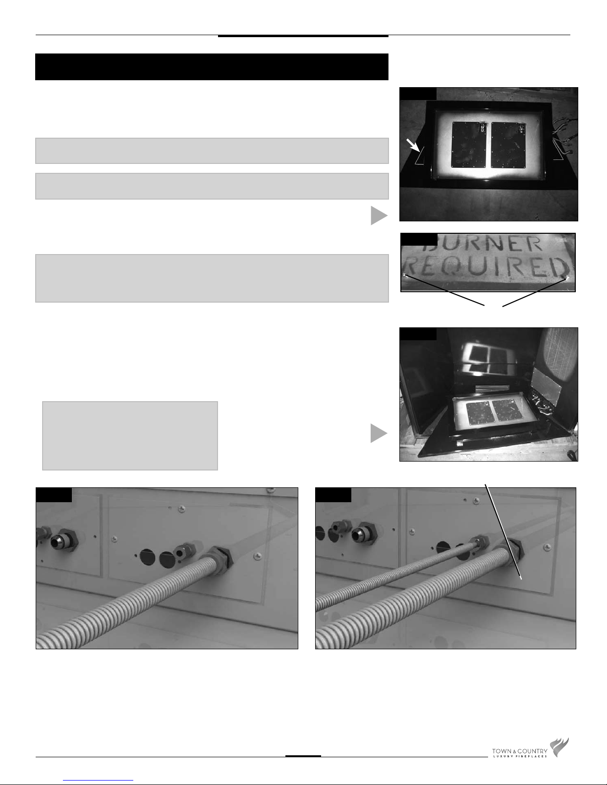
1. Position line covers on the base shield
under the burner tray, one on each side.
(Fig. #1)
NOTE:
If unit is to be converted to Propane, see Propane conversion instructions on
page 7 before proceeding.
2. Remove 2 screws in bottom of rebox.
Fig. #1b
3. Set the burner assembly into the rebox
as shown to ease connection setup
and right panel installation. Connect all
wires and fuel lines ensuring a gas tight
connection. (Fig. #2)
LINE COVER PLACEMENT
Fig #1
Fig #1b
SCREWS
Fig #2
NOTE: Pilot and manifold plumbing
and wires are grouped and tied at the
factory to ensure proper connection.
Nylon zip ties must be removed after
connections have been made, and
prior to ignition.
Fig. #3
4. Attach the manifold supply tube from the forward manifold to the
front bulk head tting and tighten. (Fig. # 3)
INITIAL BURNER PLACEMENT
FRONT CONNECTIONS
Fig. #4
5. Attach the pilot supply tube from the forward pilot to the front bulk
head tting and tighten. (Fig. # 4)
TC54.NGO4C2 070211-16
3
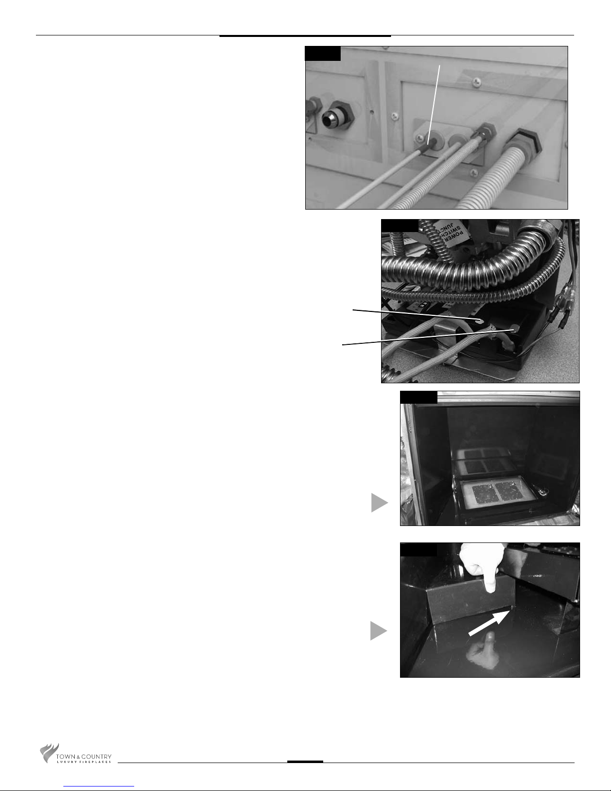
6. Remove access cover from side of rebox.
7. Remove access cover from side of rebox. Secure the bulkhead
plate and gasket to the rebox. (2 screws) Attach the ignition
and sensor wires to the module on the front valve. Red end to
the connector marked by the red dot, white end to the connector
marked by the white dot(Fig. #5b). Repeat for the rear valve.
Fig. #5
RED END
8. Repeat this process with the remaining manifold and the pilot
assembly provided with the burner kit.
WHITE END TO
WHITE DOT
9. Install right side panel as per panel installation instructions and
nalize setting burner assembly into the unit. (Fig. #6)
BURNER INSTALLED
Fig #5b
RED END TO
RED DOT
Fig #6
10. Slide the line covers out from under the burner tray and slip the
tab into the slot in the assembly base. (Fig. #7)
Fig #7
INSTALL LINE COVERS
TC54.NGO4C2 070211-16
4
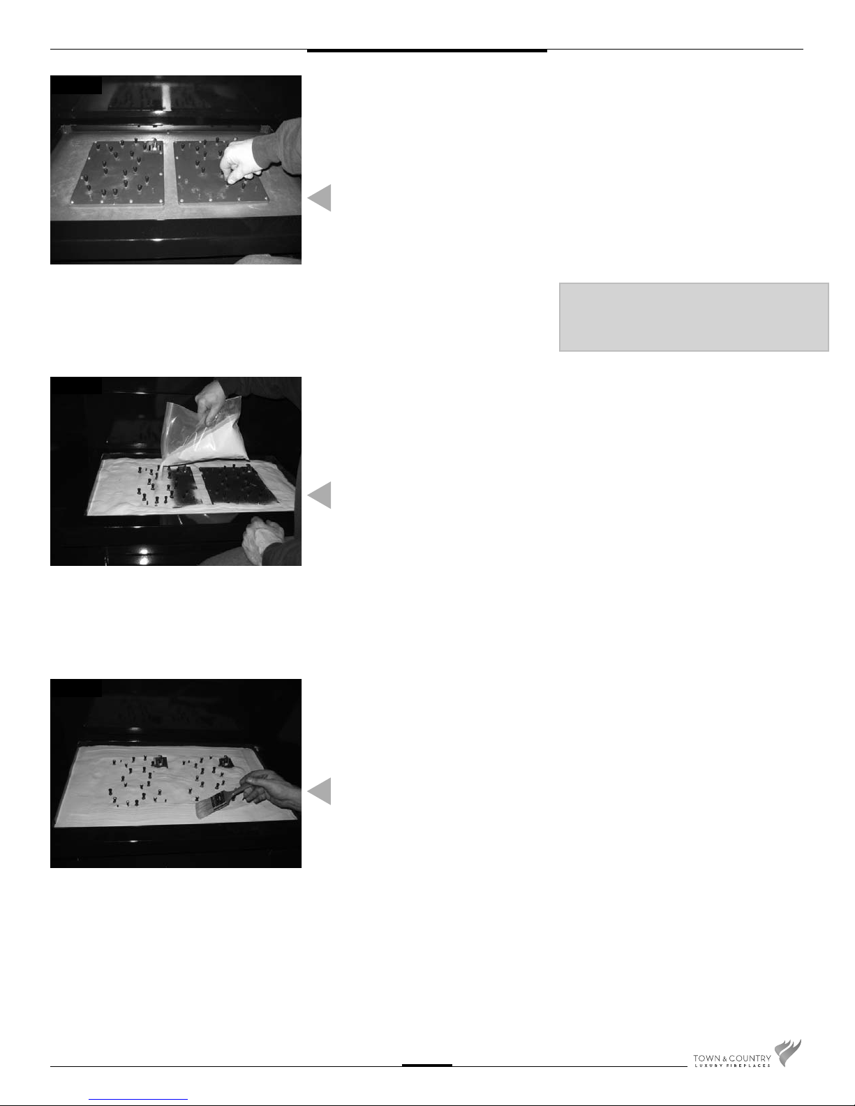
Fig #8
Fig #9
11. Place tapered plugs into all burner ports
to prevent sand from entering the burners. (Fig. #8)
PLUGGING PORTS
WITH TAPER PLUGS
CAUTION: Before pouring sand ensure all
connections and adjustments are made.
Removing sand is very difficult.
12. Pour sand evenly over tray and burners
using the entire contents. Use caution
not to let sand enter pilot locations.
(Fig. #9)
Fig #10
SAND PLACEMENT
13. Brush the sand smooth and gently blow
excess sand from around burner ports
before removing the tapered plugs.
(Fig. #10)
SAND FINISHING
TC54.NGO4C2 070211-16
5
 Loading...