

Town & Country Fireplaces TC54.NG03C2 Instructions Manual
IMPORTANT:
THESE INSTRUCTIONS ARE TO REMAIN
WITH THE HOMEOWNER
These instructions are supplementary to the Installation
and Operating Instructions supplied with the replace
and should be kept together. Refer to the Installation
and Operating Instructions for proper gas supply, safety
requirements and operating instructions.
TC54
BLACK DIAMOND
BURNER KIT
INSTRUCTIONS
070211-16 TC54.NG03C2 5056.4256203
PART# TC54.NG03C2
For TC54 Series C
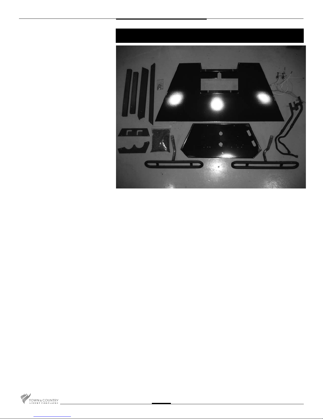
Contents of Package
N
E
F
H
J
I
A MANIFOLD ASSEMBLY
(including supply tube)
B BURNER TUBE, FRONT
C BURNER TUBE, REAR
D BURNER SHIELD
E MEDIA SPACER, Rr Center
F MEDIA SPACER, Fr Center
G MEDIA SPACER, Front
H MEDIA SPACER, Rear
I MEDIA SPACER, Left
J MEDIA SPACER, Right
K HARDWARE PACKAGE
L 5 lbs. GLASS MEDIA
M BURNER TRAY
N PILOTS
O CONVERSION KIT (not shown)
K
G
L
C
D
A
M
B
TC54.NGO3C2 070211-16
2
Black Diamond Burner Installation
NOTE:
If unit is to be converted to Propane, see Propane conversion instructions on
page 8 before proceeding.
The panel set instructions must be used when installing this burner. Typically all
panels except the right side should be installed prior to burner installation.
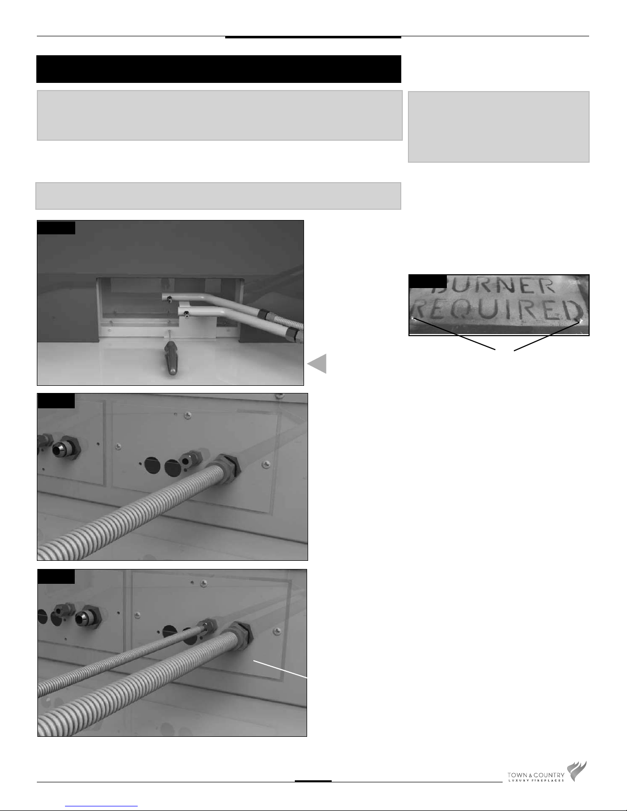
NOTE: Plug the 4 vacant holes in the bottom of the rebox with #8x1/2” screws.
The holes are not required for this style of burner.
Fig #1
1. Remove one screw from the center rear of the rebox and use
it to attach the manifold assembly. (Fig. #1)
INSTALL MANIFOLD ASSEMBLY
NOTE: Pilot and manifold plumbing and
wires are grouped and tied at the
factory to ensure proper connection.
Nylon zip ties must be removed after
connections have been made, and
prior to ignition.
Fig #1b
SCREWS
Fig. #2
Fig. #3
2. Remove the 2 screws from the rebox bottom. (Fig. #1b)
3. Attach the manifold supply tube from the lower manifold to the
front bulk head tting and tighten. (Fig. # 2)
4. Attach the pilot supply tube from the forward pilot to the front bulk
head tting and tighten. (Fig. # 3)
FRONT CONNECTIONS
TC54.NGO3C2 070211-16
3
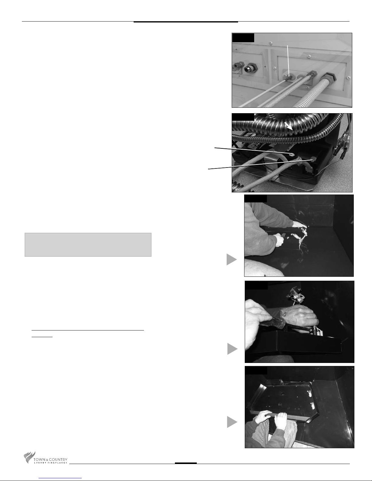
5. Remove access cover from side of rebox.
6. Remove access cover from side of rebox. Secure
the bulkhead plate and gasket to the rebox. (2
screws) Attach the ignition and sensor wires to
the module on the front valve. Red end to the
connector marked by the red dot, white end to
the connector marked by the white dot. Repeat
for the rear valve.(Fig. #4 & 4b)
Fig. #4
RED END
Fig #4b
WHITE END TO
WHITE DOT
RED END TO
RED DOT
Fig #5
7. Place burner shield into unit, exing right shield
leg slightly to clear manifold. Make sure both
pilots protrude through center hole. (Fig. #5)
NOTE: The shield sits at an approximately 15
degree angle to the base of the rebox.
8. Cover the glossy surface of the burner shield to
prevent surface damage while connecting pilots
to the underside of the burner tray.
Attach the front pilot to the front of the burner
tray rst then the rear pilot to the rear of the tray.
(Fig. #6)
NOTE: Start screws with ngers rst to prevent
cross-threading.
INSTALL SHIELD
Fig #6
ATTACH PILOTS
Fig #7
9. Place front media spacer to the front of the tray.
(Fig. #7)
INSTALL FRONT MEDIA
SPACER
TC54.NGO3C2 070211-16
4
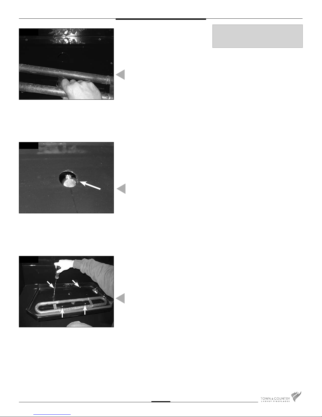
Fig #8
Set the air shutter to fully open
for Propane or fully closed for
Natural gas.
Fig #9
INSTALLING FRONT BURNER
BURNER TUBE PLACEMENT
10. Install front burner tube by tilting it into
front tray hole until almost fully seated.
(Fig. #8)
11. Guide tray and burner tube back until the
burner tube engages the forward ori ce.
This can be seen through the rear burner
hole. (Fig. #9)
Fig #10
TC54.NGO3C2 070211-16
12. Attach burner tray to shield with four
screws. (Fig. #10)
BURNER TRAY ATTACHMENT
5
 Loading...