

Town & Country Fireplaces TC54.NG02D Installation Instructions Manual

INSTALLER: Leave this manual with the appliance.
CONSUMER: Retain this manual for future reference.
These instructions are supplementary to the Installation
and Operating Instructions supplied with the fireplace
and should be kept together. Refer to the Installation
and Operating Instructions for proper gas supply, safety
requirements and operating instructions.
TC54
COUNTRY HOME
BURNER KIT
060317-20
TC54_NG02D
PART# TC54.NG02D
For TC54 Series D
Fireplaces
5056.4256202D

• Lower burner assembly (including pilot
Package Contents
and manifold)
• Log grate (including upper burner)
• 3 way gas connector
• Ember material (two bags not shown)
• Country home log set (not shown)
• Hardware package (not shown)
Figure 1: Country home package contents.
Note: If converting this fireplace from natural gas to propane at the same time as installing this new log
set, complete the propane gas conversion, See “Propane Conversion” on page 11 first to avoid possible damage to the new log set.
Burner / Grate Installation
Mounting
screws
Figure 2: Access cover to valve control center.
Figure 3: Lower burner mounting screws.
1. Remove the cover to the valve control center located on the inside right of the rebox (Figure 2).
2. If installing burner into a new replace, place the lower burner onto the oor of the replace and
secure the burner with the two mounting screws (Figure 3).
5056.4256202D
2
TC54_NG02D_060317-20
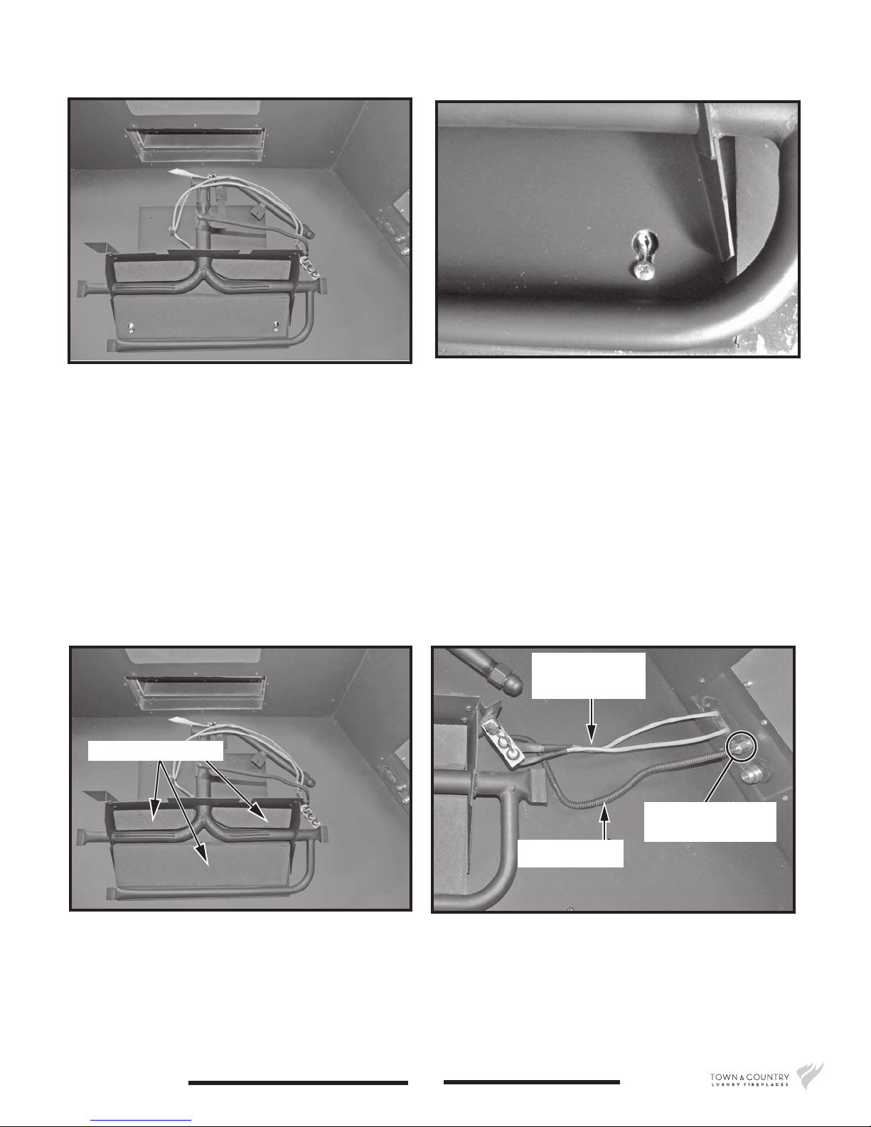
Figure 4: Lower burner placement.
Figure 5: Lower burner keyhole slot.
3. Tighten screws once the lower burner has been tted onto the keyhole slots (Figure 5).
4. Replace/insert the 3 ceramic ller pieces into the center of, and to the upper left and right hand
side of lower burner (Figure 6).
5. Connect the pilot gas tube to the gas manifold using a 1/2” wrench and feed the ignition and
ame sensor wires (Figure 7) through the bulk head plate by pushing them through into the control compartment. These wires will be connected to the IFC in a later step.
Ignition & ame
sensor wires
Ceramic ller pieces
Figure 6: Ceramic ller pieces.
TC54_NG02D_060317-20
Secure at manifold
with 1/2” wrench
Pilot gas tube
Figure 7: Lower burner gas and electrical connections.
3
5056.4256202D
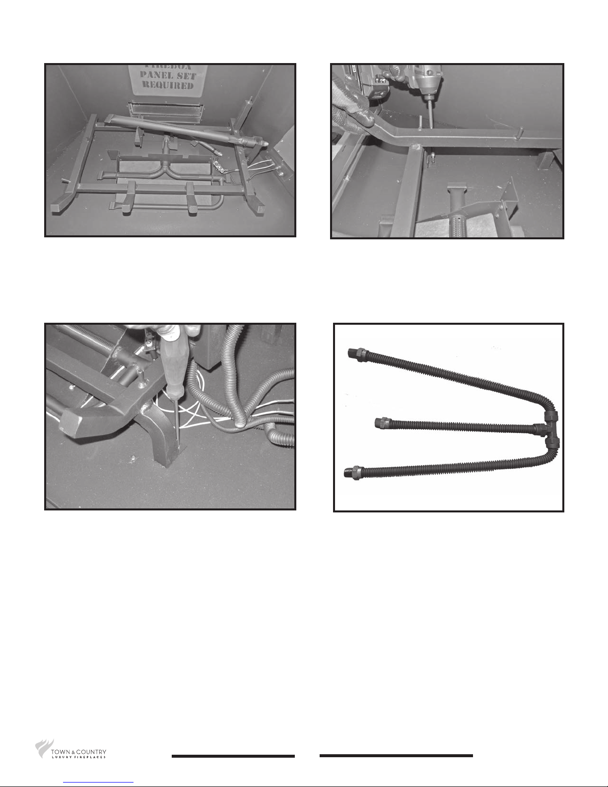
Figure 8: Log grate with upper burner.
Figure 9: Securing left side of grate to rebox oor.
6. Place the log grate with the attached upper burner onto the rebox oor (Figure 8). Locate two
screw holes on the rebox oor at the front of the grate and secure (Figure 9 and Figure 10).
Figure 10: Securing right side of grate to rebox oor.
7. The gas connector (Figure 11) will connect the upper and lower burners to the gas supply manifold. Begin by attaching the center leg of the connector to the gas tting located onto the bulkhead (Figure 12). Continue by connecting the two remaining legs of the connector to the upper
and lower burners (Figure 13). The ttings on the connectors use a 7/16” wrench.
5056.4256202D
Figure 11: Gas connector.
4
TC54_NG02D_060317-20
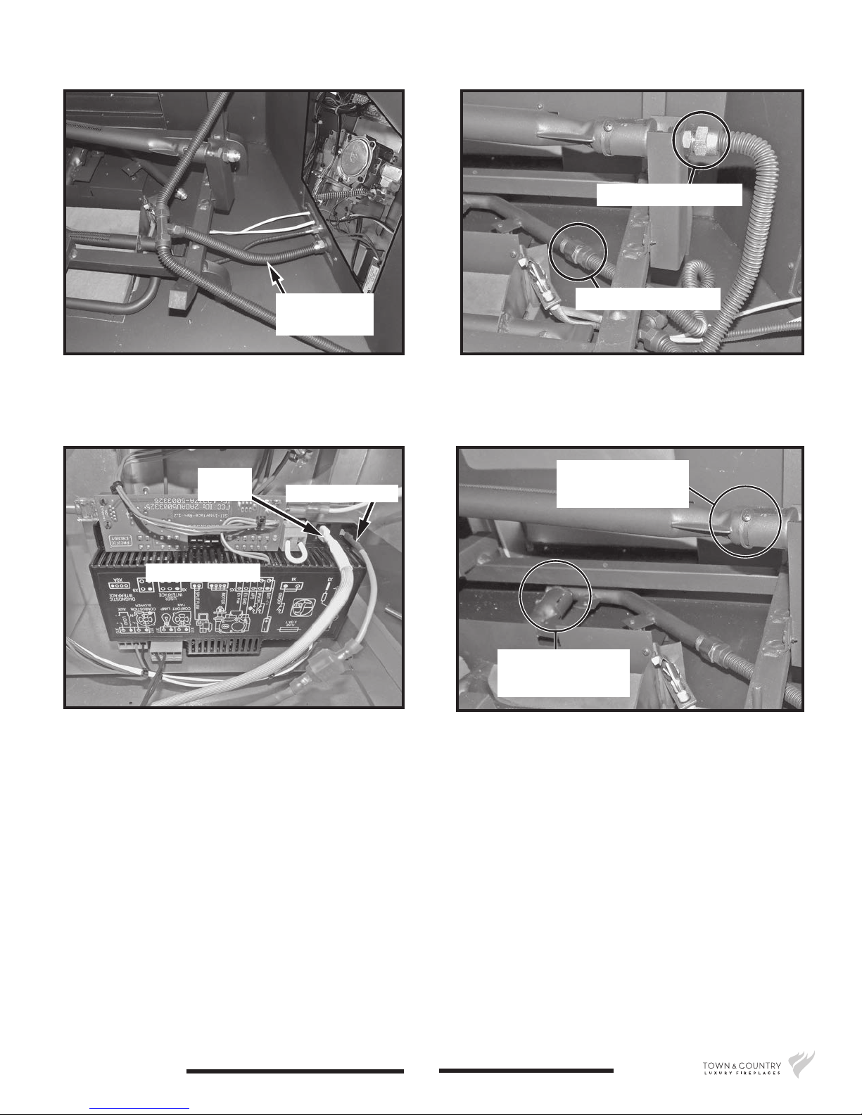
Upper gas connection
Center leg of
gas connector
Figure 12: Attaching gas connector to bulkhead tting.
Flame
sensor
Ignition wire (red)
Interface module
Lower gas connection
Figure 13: Gas connector to upper and lower burners.
Upper burner
shutter adjustment
Lower burner
shutter adjustment
Figure 14: Interface module.
8. Connect the ignition wire and the ame sensor wire to their proper terminals (Figure 14).
9. Close up the valve control center by installing the cover (Figure 2 on page 2).
10. Locate the air shutters for both the upper and lower burners (Figure 15). Adjust each of them so
that they have on opening gap of 1/8 of an inch (Figure 16 and Figure 17). This setting is for natural gas.
TC54_NG02D_060317-20
Figure 15: Air shutters locations.ai
5
5056.4256202D
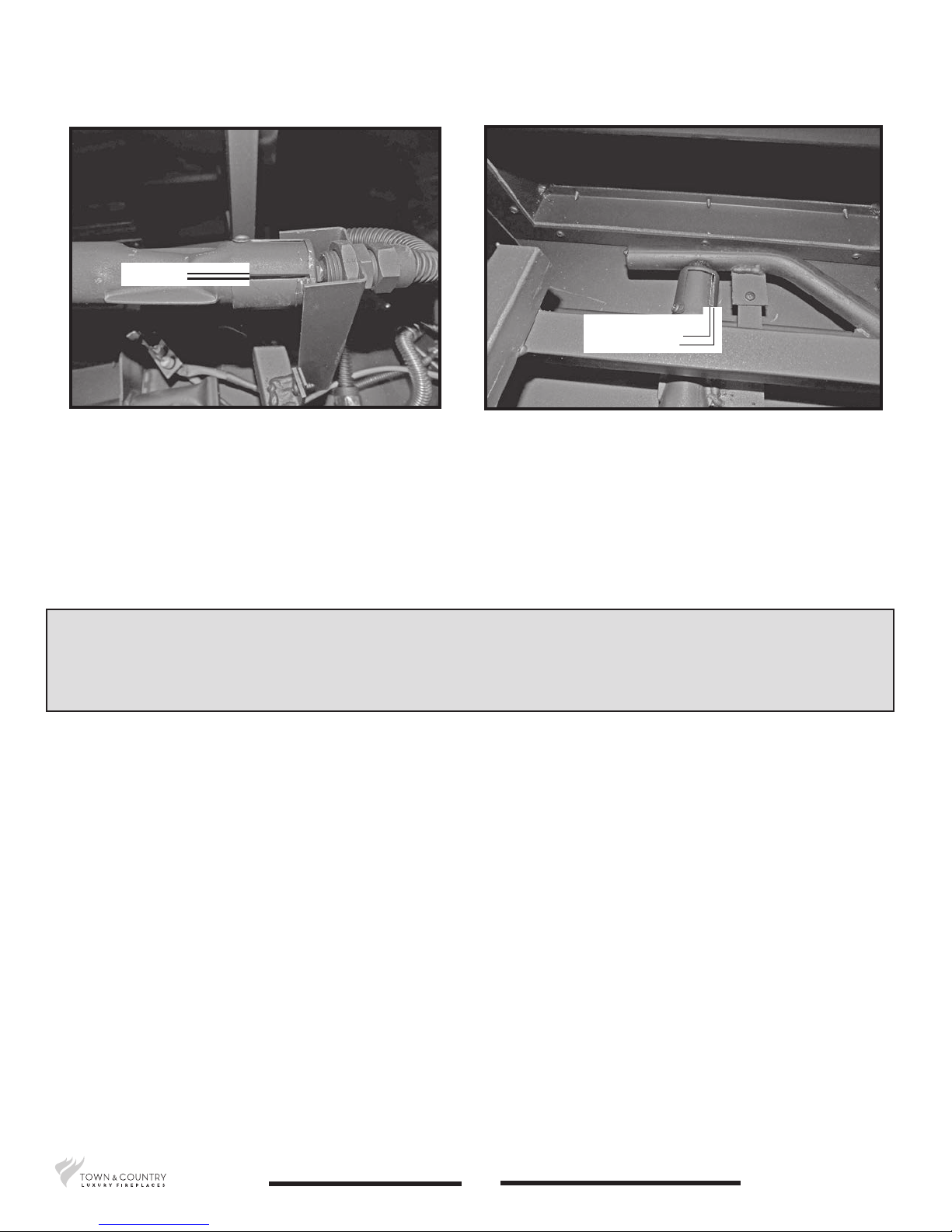
1/8” gap
1/8” gap
Figure 16: Upper burner air shutter.
Figure 17: TC54 Burner Kit lower shutter.
Note: The panel set can be installed at any time before, during or after the
burner kit has been installed. Caution should be taken to make sure that
the log grate does not scratch the panels during installation.
5056.4256202D
6
TC54_NG02D_060317-20
 Loading...