

Town & Country Fireplaces TC54.NG02C2 User Manual

INSTALLER: Leave this manual with the appliance.
CONSUMER: Retain this manual for future reference.
These instructions are supplementary to the Installation and
Operating Instructions supplied with the replace and should be
kept together. Refer to the Installation and Operating Instructions
for proper gas supply, safety requirements and operating
instructions.
TC54
COUNTRY HOME
BURNER KIT
130212-16 TC54.NG02C2 5056.4256202
PART#
TC54.NG02C2
For TC54
Series C
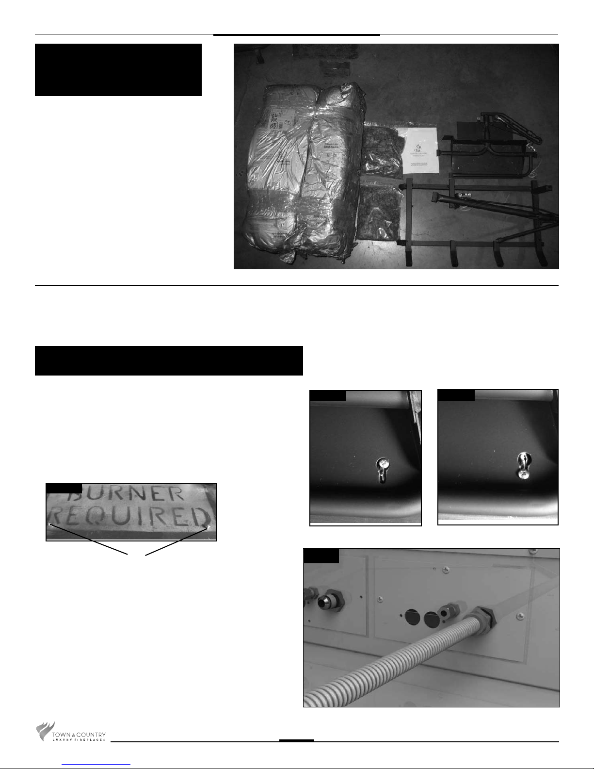
Package
Contents
• BURNER ASSEMBLY
(including pilot and manifold)
• LOG GRATE (including upper
burner and pilot assembly)
• EMBER MATERIAL (two bags)
• HARDWARE PACKAGE
Burner / Grate Installation
1. Remove ceramic ller piece from center of lower burner, set
aside. Place the keyhole slots in the burner over the two screws
located in the rebox base. (Fig. # 1-3)
2. Slide the burner back to engage the screws in the small part of
the keyhole slot and tighten screws. Replace ceramic ller piece
in center of lower burner.
Fig. # 1
SCREWS
3. Attach the manifold supply tube from the lower burner to the front
bulk head tting and tighten. (Fig. # 4) Ensure that there are no
leaks.
Fig. # 2
Fig. #4
Fig. # 3
2
130212-12 TC54.NG02C2
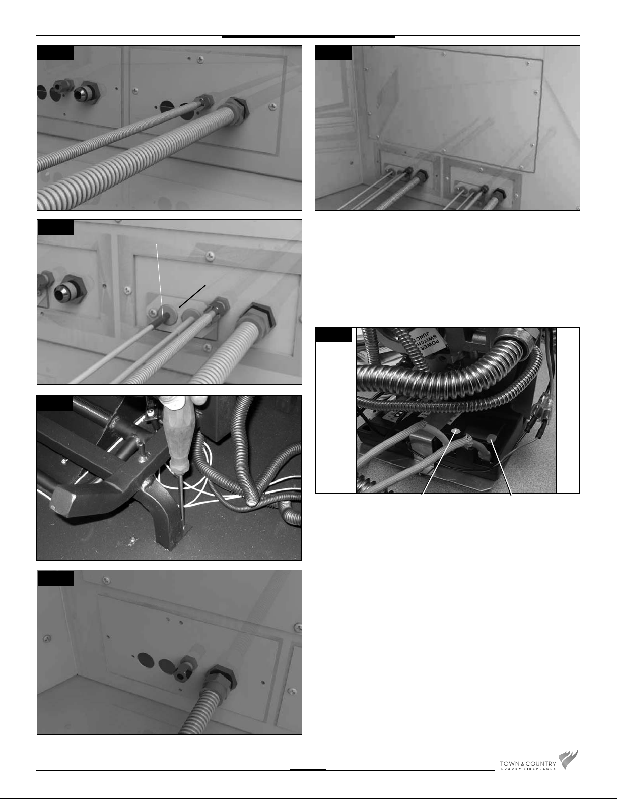
Fig. #5
Fig. #6
ACCESS COVER
FRONT CONNECTIONS
Fig. #7
Fig. #9
RED END
BULKHEAD PLATE
4. Attach the pilot supply tube from the lower burner pilot to the
front bulk head tting and tighten. (Fig. # 5)
5. Remove access cover from side of rebox. (Fig. #6) Secure the
bulkhead plate to the rebox (2 screws)(Fig. #7) Attach the ignition
and sensor wires to the control module on the front valve. Red
end to the connector marked by the red dot, white end to the
connector marked by the white dot. (Fig. #8)
Fig. #8
WHITE END TO
WHITE DOT
RED END TO
RED DOT
Fig. #10
130212-12 TC54.NG02C2
6. Position the grate and attach it to the oor with two screws located
behind the front legs. (Fig. # 9)
7. Attach the manifold supply tube from the upper burner to the
rear bulk head tting and tighten. (Fig. # 10) Ensure that there
are no leaks.
3
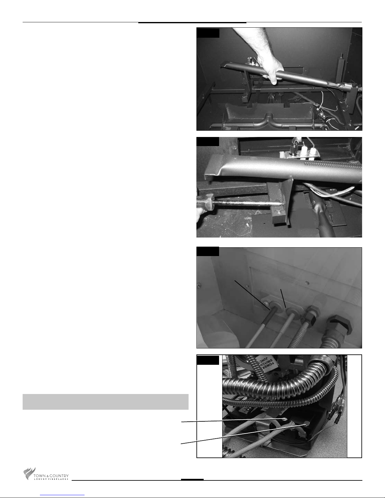
8. Install the upper burner/ pilot assembly. Ensure that the ori ce
engages fully into the burner and the shutters on both burners
are 1/8” open. (Figs. #11 and 12)
Fig. #11
Fig. #12
9. Attach the pilot supply tube from the upper burner pilot to the
rear bulk head tting and tighten. (Fig. # 13)
10. Secure the bulkhead plate to the rebox. (2 screws) Attach the
ignition and sensor wires to the module on the rear valve. Red
end to the connector marked by the red dot, white end to the
connector marked by the white dot. (Fig #14)
A panel set must now be installed. See Installation and
Operating Instructions manual for details.
WHITE END TO
WHITE DOT
Fig. #13
RED END
BULKHEAD PLATE
REAR CONNECTIONS
Fig. #14
RED END TO
RED DOT
4
130212-12 TC54.NG02C2
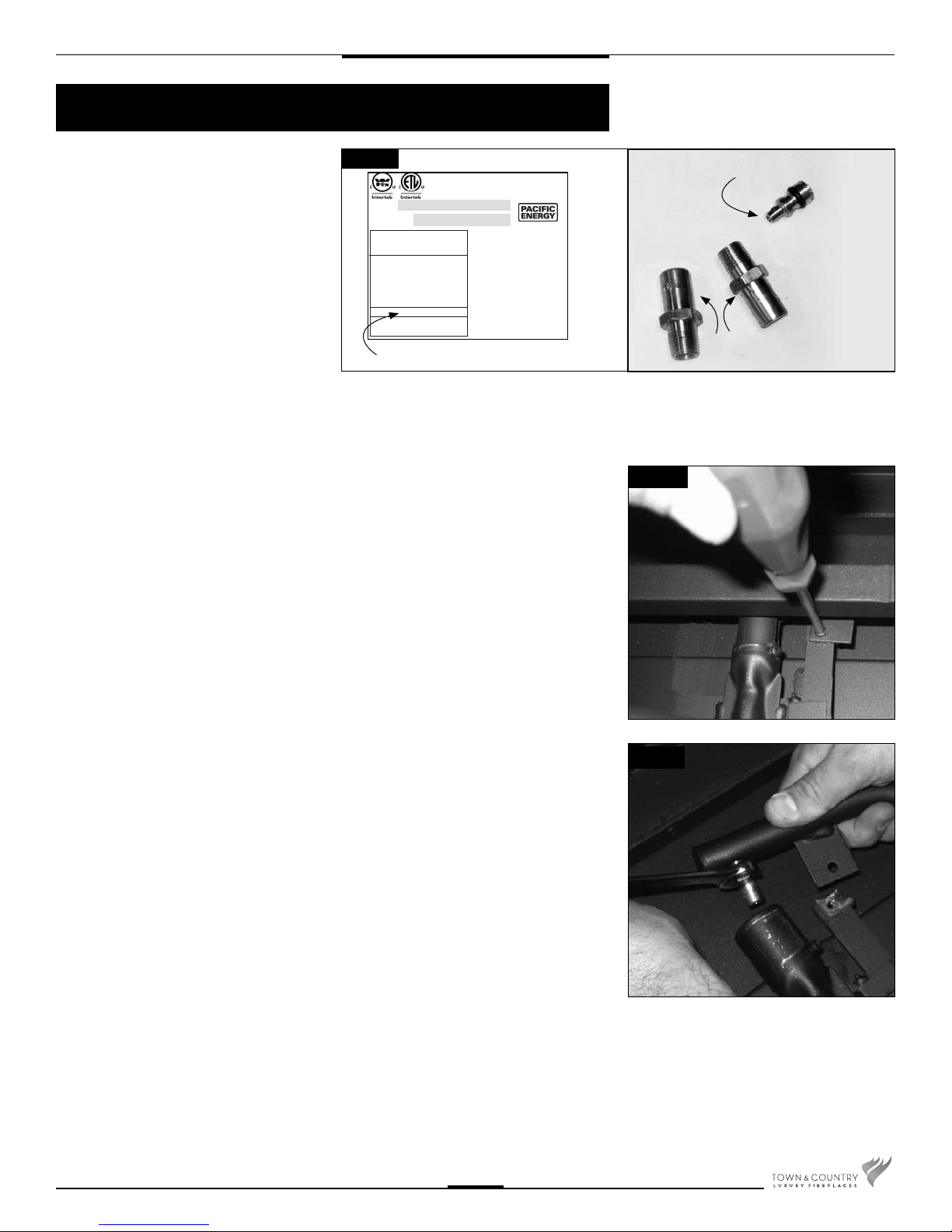
Propane Conversion
If the unit is to be used on propane con-
Fig #15a
vert as follows using the components
supplied with this replace:
WARNING
This conversion kit shall be
installed by a quali ed service
agency in accordance with the
manufacturer's instructions
and all applicable codes and
requirements of the authority
having jurisdiction. If the
information in these instructions
is not followed exactly, a re,
explosion or production of carbon
monoxide may result causing
property damage, personal
injury or loss of life. The quali ed
service agency is responsible
for the proper installation of this
kit. The installation is not proper
and complete until the operation
of the converted appliance is
checked as speci ed in the
manufacturer's instructions
supplied with the kit.
1. Ensure the burners, pilots and gas supply
2. Remove the two screws securing the
PROPANE CONVERSION KIT
Kit# TC54.LPCE02 for use with model /
Pour utilise avec du modèle: TC54.CE2
Date: ______________________
By / Par: ___________________
LP GAS/
DU GAZ LP
12.5 in/wc /12.5 po/c.e.
(3.11 kPa)
13.9 in/wc / 13.9 po/c.e.
(3.45 kPa)
11.0 in/wc / 11.0 po/c.e.
(.95 kPa)
#44 (2.18 mm)
Max.: 83,700 (24.53)
Min.: 67,000 (19.63)
CONVERSION LABEL (5052.520862)
This appliance was converted to PROPANE GAS
with this kit on this date
by the organization which
accepts the responsibility
that this conversion has
been properly made. / Cet
appariel etair converter au
gaz LP par l’emploi de la
trousse de conversion par
une organization qui accepte la responsibilité pour
une installation en bon état.
230910 6-TC54C2 5052.520862
are turned off, and the appliance has
cooled.
manifold assembly to the lower burner,
(Fig. #15b)
MINIMUM RATE SCREW (5005.015 x2)
MAIN BURNER
(#44) ORIFICES (5022.92)
Fig. #15b
CAUTION
The gas supply and electrical power
shall be shut off before proceeding
with the conversion.
Note: Factory supplied components must be
used to ensure correct input. After conversion
con rm proper manifold pressure.
Fig. #16
3. Using a 1/2” wrench, undo the natural
gas burner ori ce, (marked #29). (Fig.
#16)
130212-12 TC54.NG02C2
5
 Loading...