

Town & Country Fireplaces TC54.LP02.C User Manual

INSTALLER: LEAVE THIS MANUAL WITH
APPLIANCE
CONSUMER: RETAIN THIS MANUAL FOR
FUTURE REFERENCE
These instructions are supplementary to the Installation
and Operating Instructions supplied with the replace
and should be kept together. Refer to the Installation
and Operating Instructions for proper gas supply, safety
requirements and operating instructions.
TC54
COUNTRY HOME
BURNER KIT
TC54.LP02.C
(PROPANE ONLY)
PART# TC54.LP02.C
061107-12 TC54.LP02.C 5056.4256.025
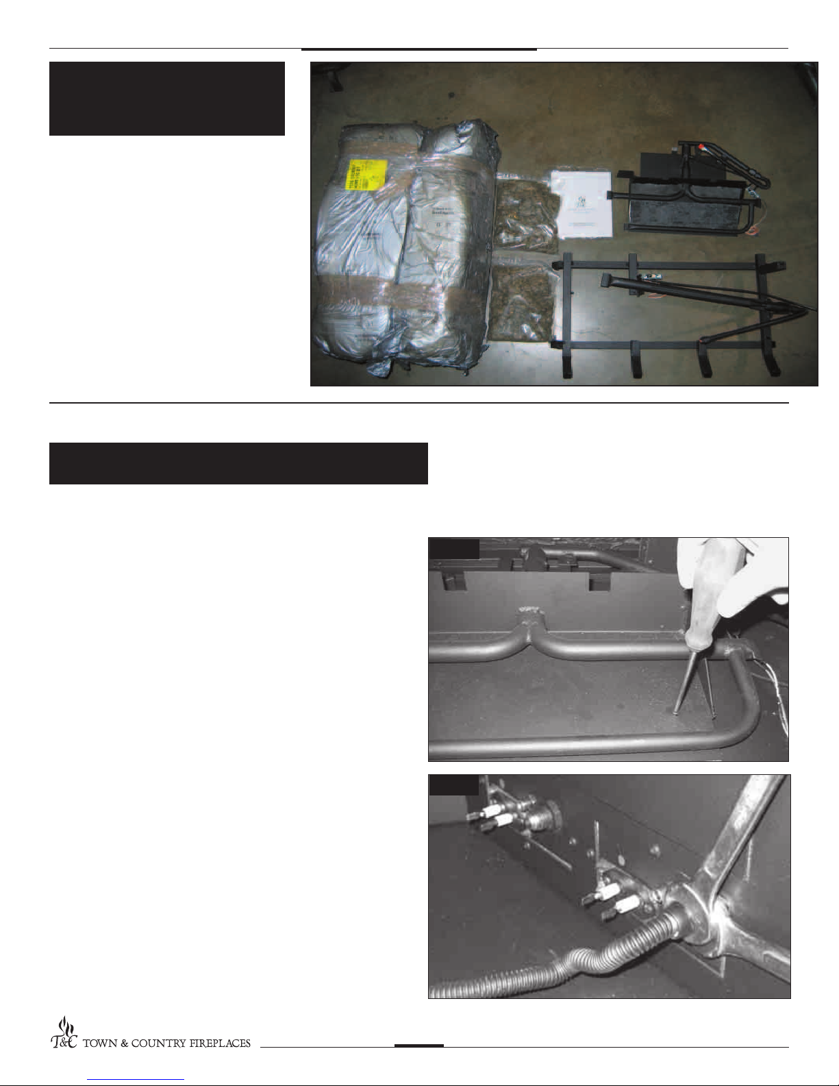
Package
Contents
• BURNER ASSEMBLY
(including pilot,manifold and
ceramic bre ller pieces)
• LOG GRATE (including upper
burner and pilot assembly)
• LOG PACK
• EMBER MATERIAL (two bags)
• HARDWARE PACKAGE
Burner / Grate Installation
1. Attach the lower burner assembly to the oor of the rebox with
two screws. (Fig. # 1)
2. Attach the manifold supply tube from the lower burner to the front
bulk head tting and tighten. (Fig. # 2) Ensure that there are no
leaks.
Fig. #1
Fig. #2
061107-12 TC54.LP02.C
2
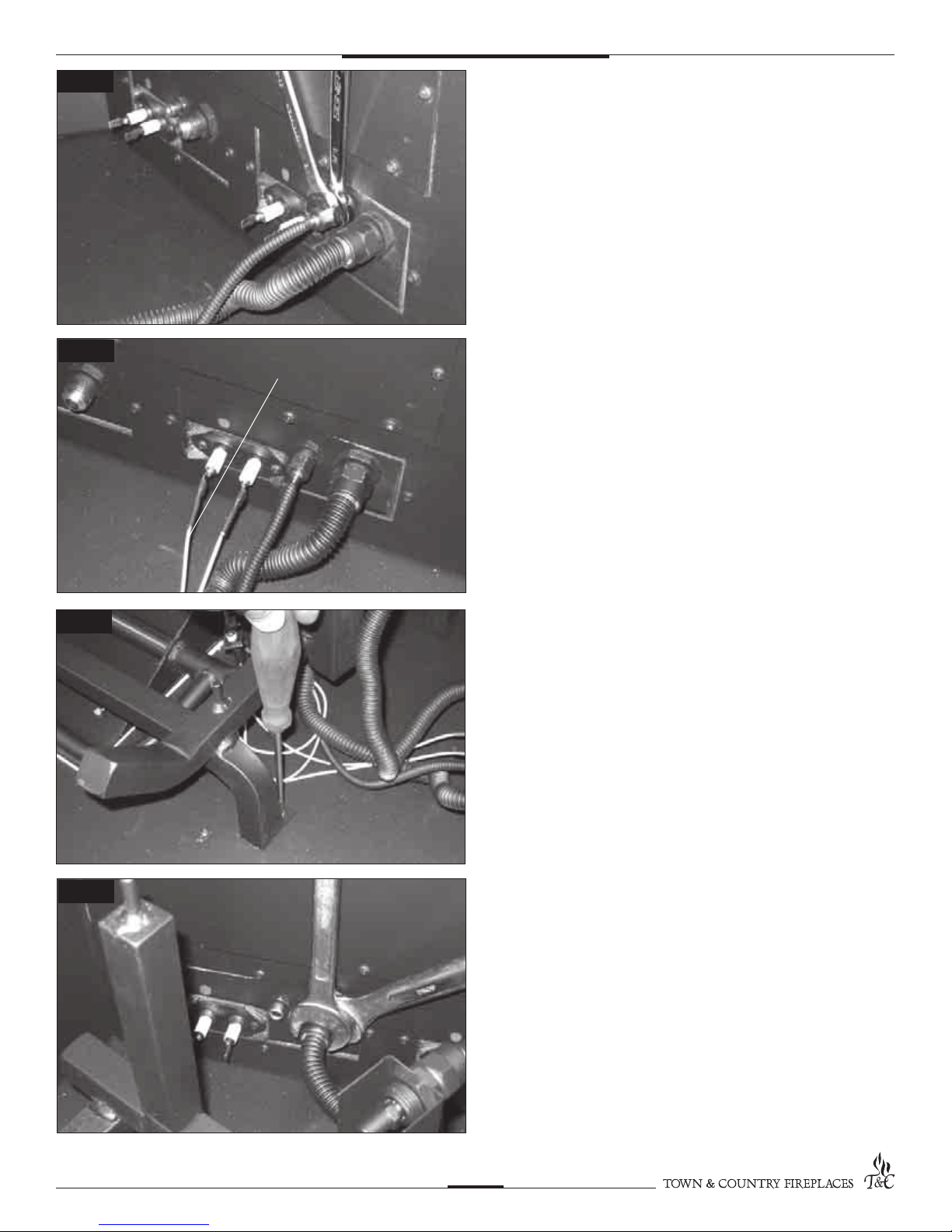
Fig. #3
3. Attach the pilot supply tube from the lower burner pilot to the
front bulk head tting and tighten. (Fig. # 3) Ensure there are no
leaks.
Fig. #4
Fig. #5
ORANGE WIRE
4. Attach spark electrode (ORANGE) and sensor leads from lower
burner pilot to the front electrical bulk head. ( Fig. # 4) (The spark
electrode connection has a red dot above it)
5. Position the grate and attach it to the oor with two screws located
behind the front legs. (Fig. # 5)
Fig. #6
061107-12 TC54.LP02.C
6. Attach the manifold supply tube from the upper burner to the
rear bulk head tting and tighten. (Fig. # 6) Ensure that there are
no leaks.
3
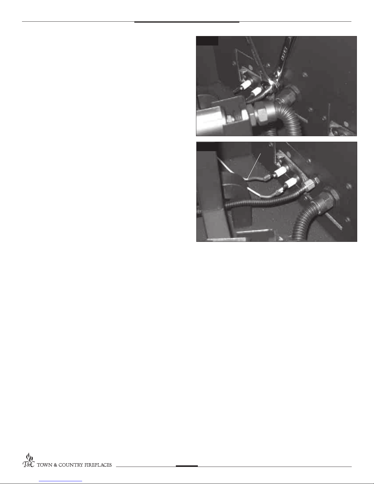
8. Attach the pilot supply tube from the upper burner pilot to the
rear bulk head tting and tighten. (Fig. # 7) Ensure there are no
leaks.
Fig. #7
9. Attach spark electrode (ORANGE) and sensor leads from upper
burner pilot to the rear electrical bulk head. (Fig. # 8) (The spark
electrode connection has a red dot above it)
A panel set must now be installed. See Installation and
Operating Instructions manual for details.
Fig. #8
ORANGE WIRE
061107-12 TC54.LP02.C
4
 Loading...