

Town & Country Fireplaces TC42.NG06D2 Installation Instructions Manual
INSTALLER: Leave this manual with the appliance.
CONSUMER: Retain this manual for future reference.
These instructions are supplementary to the Installation and
Operating Instructions supplied with the replace and should be
kept together. Refer to the Installation and Operating Instructions for
proper gas supply, safety requirements and operating instructions
TC42
CHALET
BURNER KIT
INSTALLATION
INSTRUCTIONS
Visit www. townandcountryfireplaces.net for the most recent version of this manual
060117-16 TC42_NG06D 5056.426D2-A
PART# TC42.
NG06D2
For TC42 Series D
Fireplaces
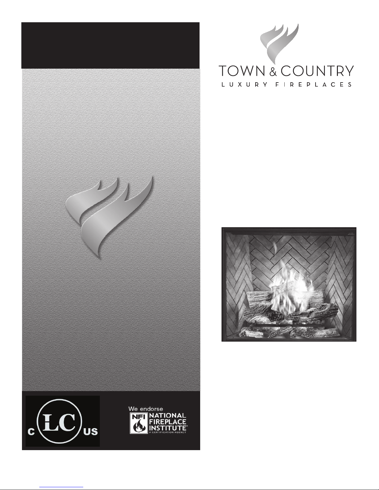
• BURNER ASSEMBLY
• LOG GRATE
• LOGS
• EMBER MATERIAL
• HARDWARE PACKAGE
If this fireplace is to be
used on Propane please
convert prior to installtion.
See pages 9 – 11.
Contents of Package
Figure 1: Package contents.
Burner Installation
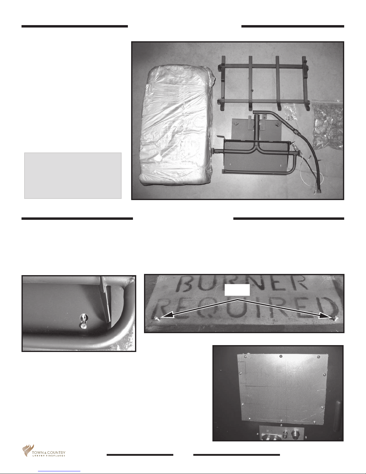
1. Place the keyhole slots in the burner (Figure 2) over the two screws located in the rebox base (Figure 3).
2. Slide the burner back to engage the screws in the small part of the keyhole slot and tighten screws.
3. Remove access cover from side of rebox (Figure 4).
Bolts
Figure 3: Bolts for burner.
Figure 2: Attaching burner to oor of
replace.
5056.426D2-A
Figure 4: Control center
access cover.
2
TC42_NG06D_060117-16
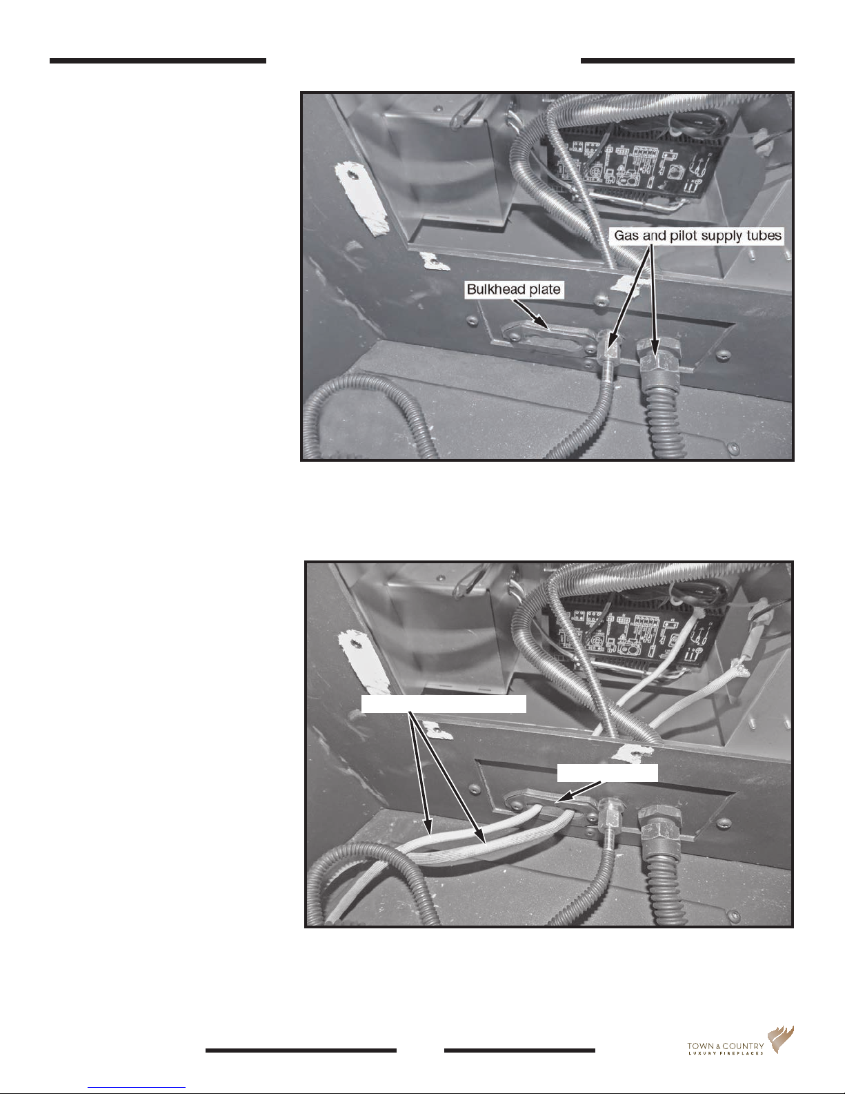
4. Attach the manifold gas and
pilot supply tubes to the bulk
head tting and tighten
(Figure 5).
Ensure that all connections are
gas tight.
Burner/ Grate Installation
2 SCREWS
Figure 5: Gas and pilot supply tubes.
5. Feed the ignition and sensor
wires through the bulkhead
plate (Figure 6) to the interface.
Ignition and sensor wires
Bulkhead plate
Figure 6: Ignition and sensor wires routing.
TC42_NG06D_060117-16
3
5056.426D2-A
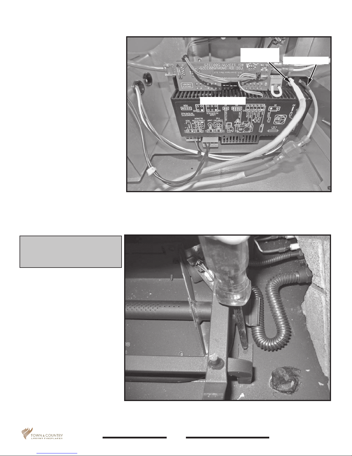
6. Attach the ignition and sensor
wires to the module (Figure 7).
7. Replace the access cover
(Figure 4: Control center
access cover. on page 2)
A panel set must now be installed.
See Installation and Operating
Instructions manual for details.
Figure 7: Interface module.
Interface module
Flame sensor
wire (white)
Ignition wire (red)
8. Position the slots of the grate
securing brackets over the holes
in the oor shield and secure
with the two screws (Figure 8).
5056.426D2-A
Figure 8: Securing the grate.
4
TC42_NG06D_060117-16
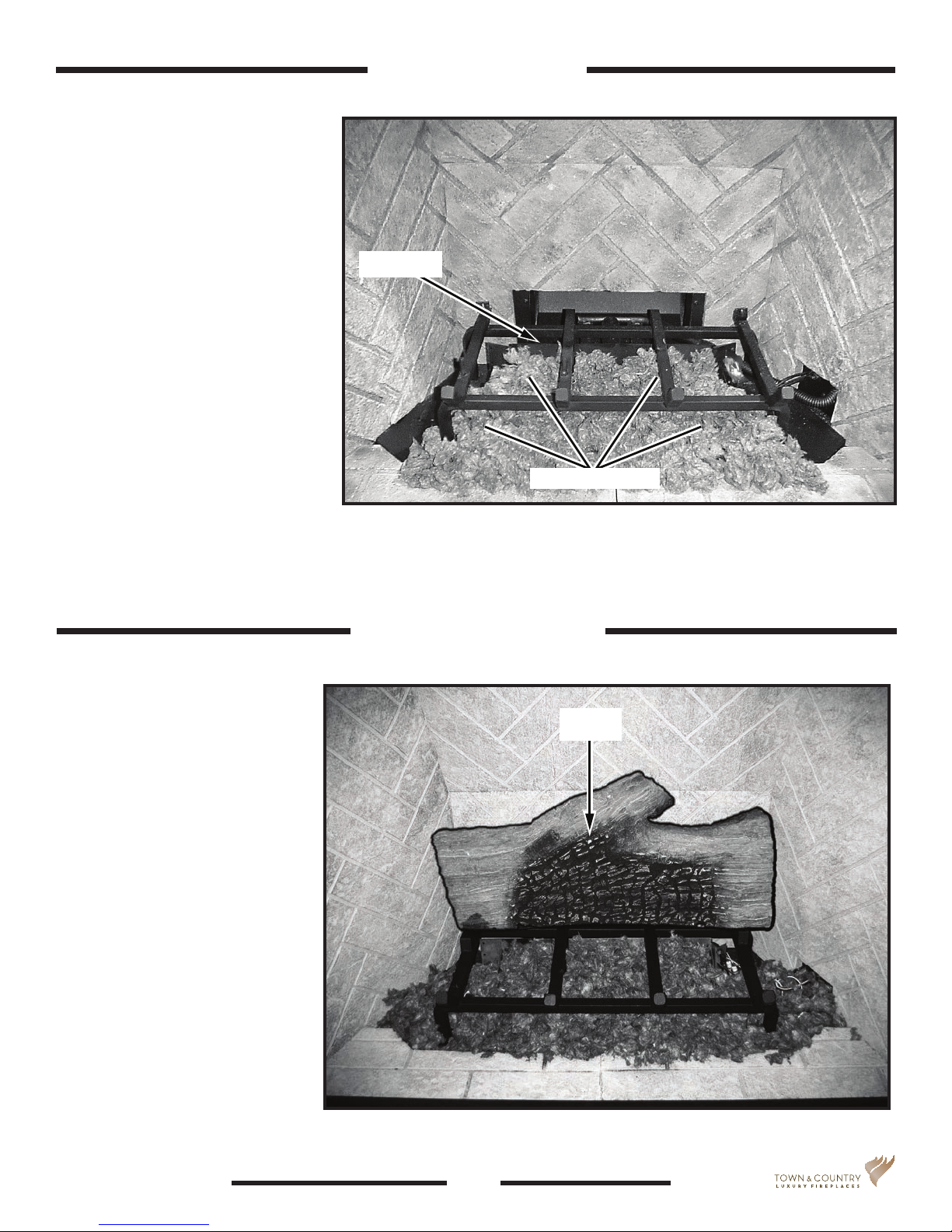
A large bag of glowing ember
material is supplied with the burner
kit and needs to be installed on the
burner to ensure optimum performance and ame appearance.
Ember Material
1. Pull apart the material into
ember size pieces (approximately 1” squares) and gently
place them into the burner pan.
Do not compress, leave them
loose for best performance.
2. Fill the burner pan level with
the top of the pan at rear, and
gradually sloping forward down
to the rebox oor at the front,
covering both burner tubes.
3. Place remaining ember material outside of the burner pan
as desired to cover-up gas
lines and brackets.
Gas plumbing and vent connections should be completed before
proceeding.
The logs are are fragile and
should be handled with care.
Unpack and inspect log set.
There should be a total of 7 logs.
Log grate
Glowing embers
Figure 9: Ember material placement.
Note: Ember material placement and amount will affect flame
appearance. More ember material results in lower flame height.
Add or remove as needed until desired flame affect.
Log Set Assembly
Log 1
Position the logs as indicated by
the following pictures. Place the
rear log back against the tabs
located at the back of the grate.
(Figure 10).
TC42_NG06D_060117-16
Figure 10: Log 1 placement.
5
5056.426D2-A
 Loading...