

Town & Country Fireplaces TC42, TC42.NG02.C Instructions Manual

INSTALLER: Leave this manual with the appliance.
CONSUMER: Retain this manual for future reference.
These instructions are supplementary to the Installation and
Operating Instructions supplied with the replace and should be
kept together. Refer to the Installation and Operating Instructions
for proper gas supply, safety requirements and operating
instructions
TC42
COUNTRY HOME
BURNER KIT
INSTRUCTIONS
270409-12 TC42.NG02.C 5056.426.C2
PART#
TC42.NG02.C
FOR TC42
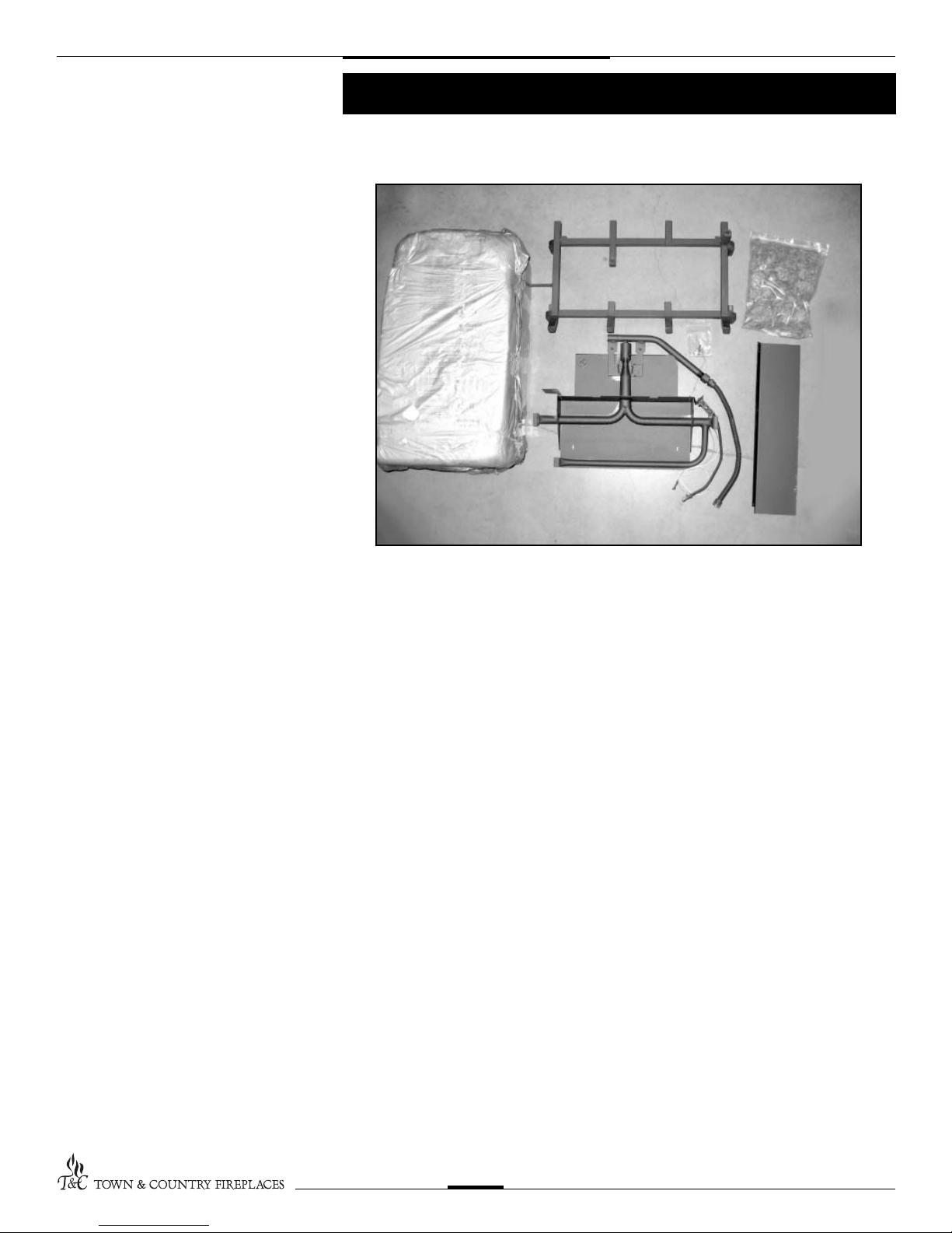
Contents of Package
• BURNER ASSEMBLY (including pilot and manifold)
• LOG GRATE
• TC42 LOGS
• EMBER MATERIAL
• HARDWARE PACKAGE
• AIR DEFLECTOR
TC42.NG02.C 270409-12
2
Burner/ Grate Installation
Fig. # 1
Fig. # 2
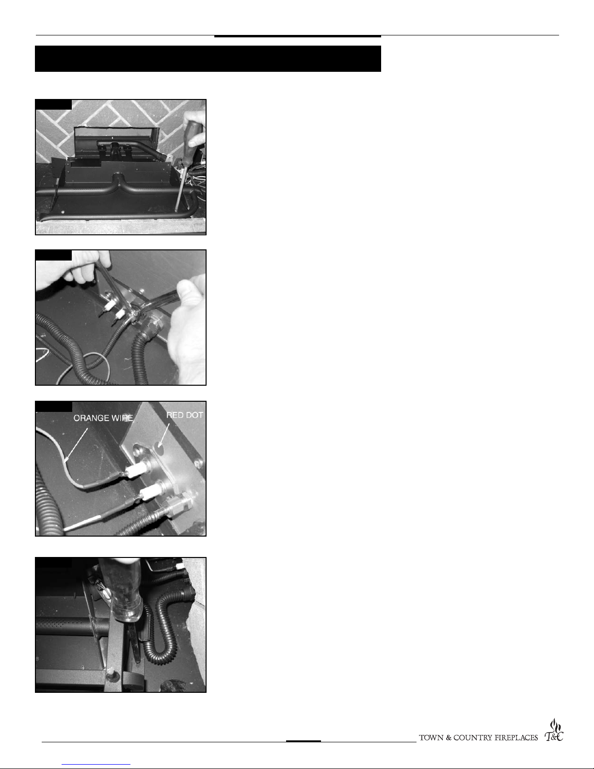
1. Attach the burner assembly to the oor of
the rebox with two screws. (Fig. # 1)
2. Connect ex lines from the manifold and
pilot assemblies to the bulkhead in the
rebox side. (Fig. # 2) Ensure that the
connection is gas tight.
Fig. # 3
Fig. # 4
3. Attach spark electrode (ORANGE) and
sensor leads to the electrical bulk head.
(Fig. # 3) (The spark electrode connection
has a red dot above it)
A panel set must now be installed. See
Installation and Operating Instructions
manual for details.
4. Position the grate in the slots of the
burner tray and attach to the oor with
two screws through holes located behind
the front legs of the grate. (Fig. # 4)
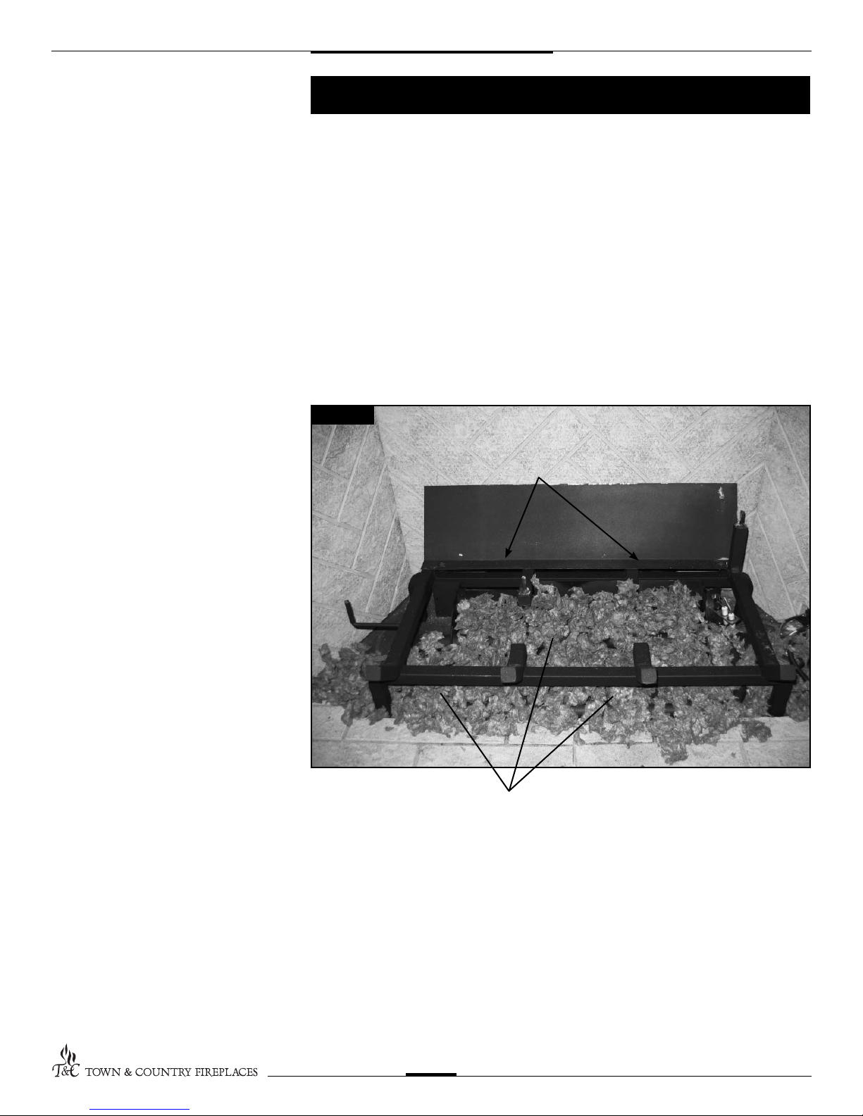
5. Attach rear de ector to rear of grate using
the two screws provided. (Fig. # 5)
TC42.NG02.C 270409-12
3
Ember Material Placement
A large bag of ember material is shipped with the replace and needs to be installed to
ensure optimum performance and ame appearance.
Pull apart the material into ember size pieces (approximately 1” squares) and gently place
them into the burner pan. Do not compress, leave it loose for best performance.
Fill the burner pan level with the top of the pan at rear, and gradually slope forward to the
rebox oor at the front, covering both burner tubes.
Place remaining ember material outside of the burner pan as desired to cover-up gas lines
and brackets.
Note: Ember material placement and amount will affect ame appearance. More ember
material results in lower ame height. Add or remove as needed until desired ame affect
is achieved.
Fig. # 5
AIR DEFLECTOR
SECURING
SCREWS
GLOWING EMBERS
TC42.NG02.C 270409-12
4
 Loading...