

Town & Country Fireplaces TC42, TC42.NG02 Instructions Manual

260805-8 TC42.NG02 5056.426.2
IMPORTANT:
THESE INSTRUCTIONS ARE TO REMAIN
WITH THE APPLIANCE INSTRUCTIONS
These instructions are supplementary to the Installation and
Operating Instructions supplied with the fireplace and should
be kept together. Refer to the Installation and Operating
Instructions for proper gas supply, safety requirements and
operating instructions.
TC42
COUNTRY HOME
BURNER KIT
INSTRUCTIONS
PART#
TC42.NG02
FOR TC42
2
260805-8 TC42.NG02 5056.426.2
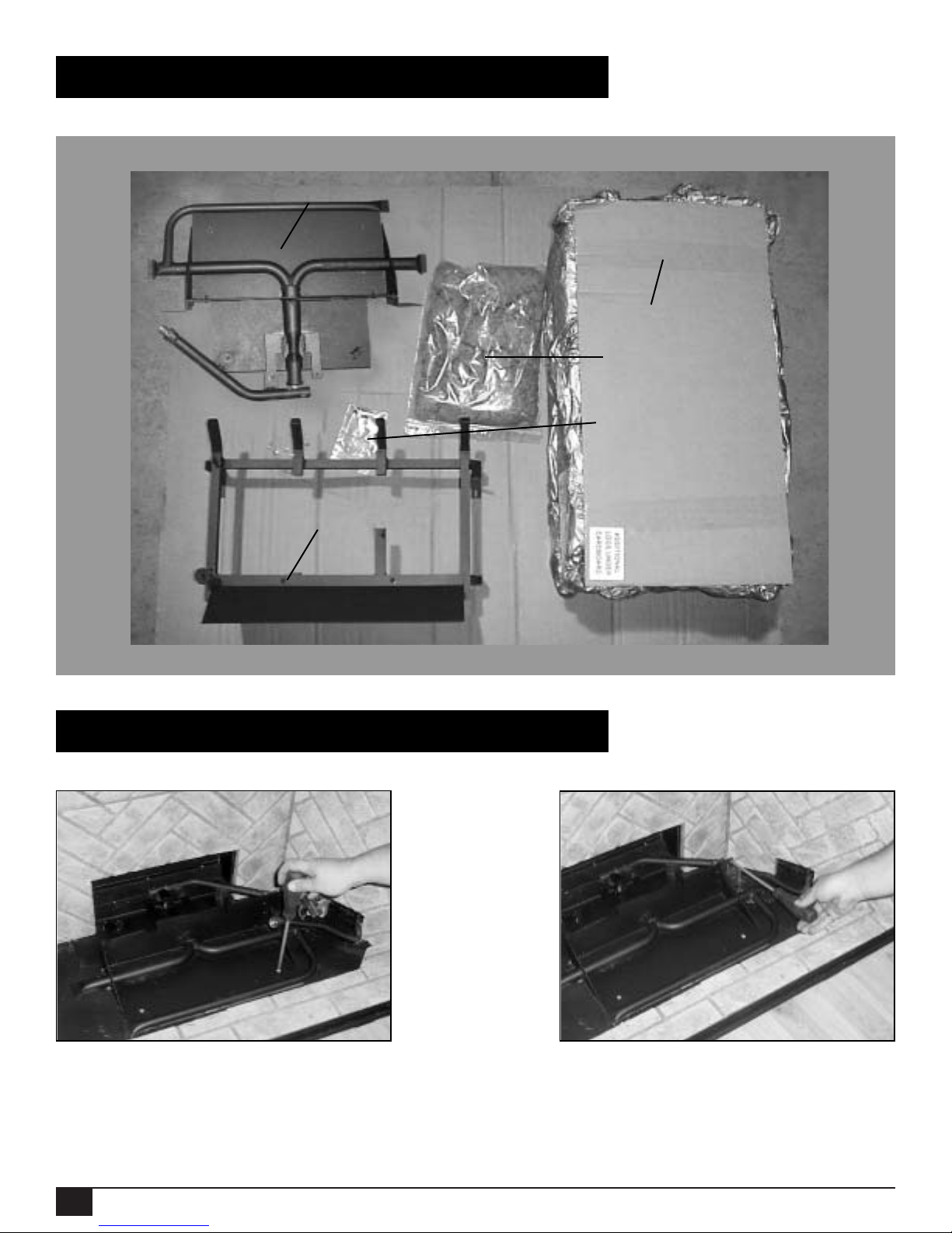
Contents of Package
Burner/Grate Installation
1. Attach the burner assembly to the bottom of
the firebox with two screws (Fig.#1).
2. Attach pilot bracket to bur ner assembly
(Fig. #2).
Fig. #1
Fig. #2
HARDWARE PACKAGE
PART# TC42.NGHDWR
EMBER MATERIAL
PART# 5096.981.B
7 PCS LOG SET
PART# 5098.311
LOG GRATE PART# TC42.90821
BURNER ASSEMBLY PART# TC42.90859
3
260805-8 TC42.NG02 5056.426.2
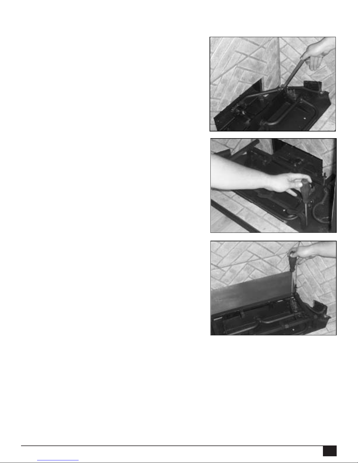
3. Connect flex gas line to the manifold
assembly and ensure the connection
is gas tight (Fig #3).
4. Position the the slots of the grate
securing brackets over the holes in
the floor shield and secure with two
screws (Fig. #4).
5. Attach air deflector to rear of grate
with two screws (Fig. #5).
NB:
Two air deflectors are supplied with
this kit; one painted, one porcelain
black.Only use the porcelain black
deflector if using optional porcelain
black liner panels.
Fig. #3
Fig. #4
Fig. #5
 Loading...