

Town & Country Fireplaces TC42.NG01 User Manual
CHALET BURNER KIT
TC42.NG01
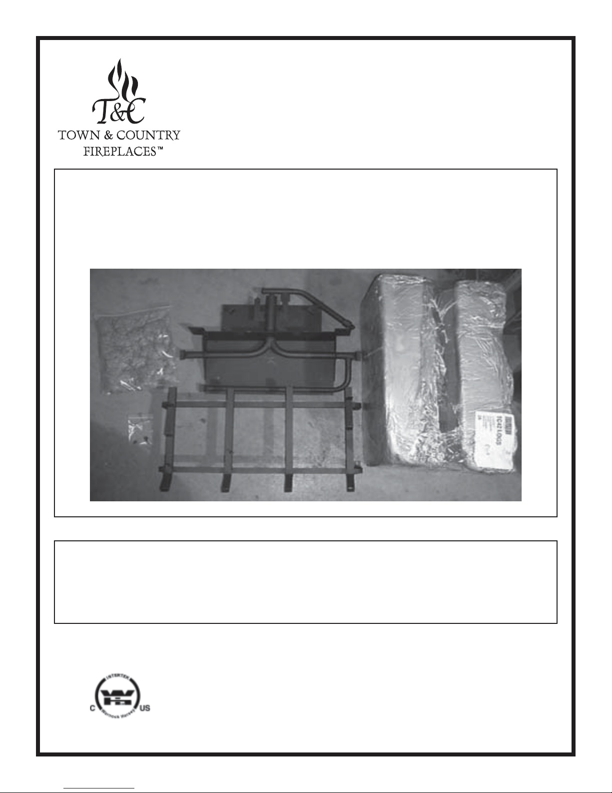
PACKAGE CONTENTS:
• BURNER ASSEMBLY PART # TC42.908501
• LOG GRATE PART # TC42.9081
• TC42 LOGS PART # 5098.31061
• EMBER MATERIAL PART # 5096.981.B
• HARDWARE PACKAGE PART # TC36.NGHDWR
These instructions are supplementary to the Installation and Operating
Instructions supplied with the replace and should be kept together. Refer
to the Installation and Operating Instructions for proper gas supply, safety
requirements and operating instructions.
IMPORTANT: THESE INSTRUCTIONS
110505-8 TC42.NG01 5056.426.1
ARE TO REMAIN WITH THE
APPLIANCE INSTRUCTIONS
CONTROL BOX RELOCATION
The gas control system is housed in a control box remote
of the replace. Flexible conduits attach the control box to
the replace and house all the the plumbing and wiring to
the burner.
The control box is shipped inside the rebox and needs to
be installed. Although the control box may be installed on the
right or left side, the replace is assembled at the factory to
accept the control box from the right hand side.
If installing on the left hand side, the casing and rebox inlet
covers must rst be removed and reinstalled on the opposite
side of the unit. The manifold will also need to be repositioned
once the burner is installed. This is done by removing two
retaining screws, turning the manifold over and re-attaching.
See Fig. #3.
DEFAULT INSTALLATION
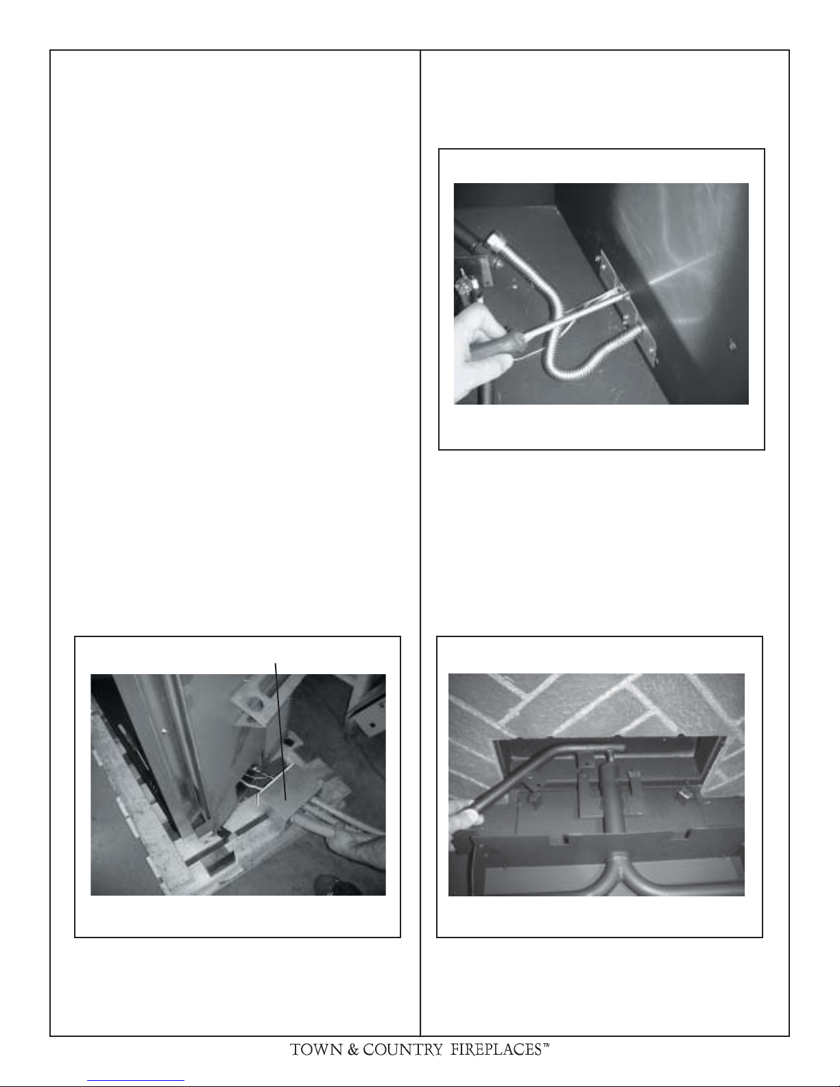
1) Insert the inlet box into the opening at the base of the right
hand side of the unit as shown in g # 1 taking care not
to damage pilot, plumbing or wires.
2) Install 4 screws from the inside of the rebox to secure
the inlet box to the rebox.
3) Install Panel Set (Refer to “Firebox Panels Installation” in
the Installation and Operating Instructions manual)
Fig. # 2
INSTALL SCREWS TO SECURE INLET BOX
A panel set must be installed prior to the installation of
the burner/grate assembly. See Installation and Operating
Instructions manual for details.
INLET BOX
INSERT CONTROL ASSEMBLY
Fig. # 3Fig. # 1
REPOSITION MANIFOLD
2 TC42.NG01 110505-8
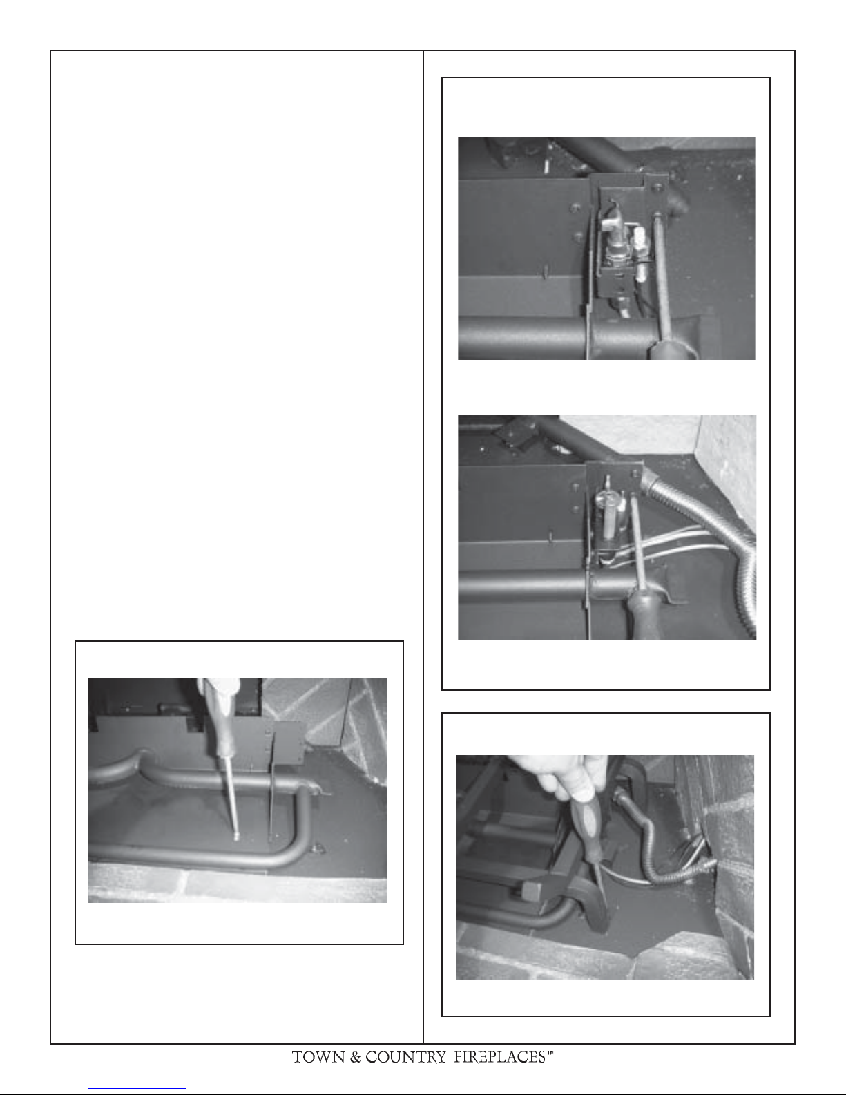
BURNER/GRATE INSTALLATION
1) Attach the burner assembly to the oor of the rebox with
two screws .
See Fig. # 4.
2) Attach pilot bracket to burner assembly using 2 #8 x 5/16
type F. See Fig. # 5.
3) Connect ex gas line to the manifold assembly and ensure
the connection is gas tight. See Fig. # 5.
4) Position the grate in the slots of the burner tray and attach
to the oor with two screws through holes located behind
the front legs of the grate. See Fig. # 6.
Fig. # 5
ELECTRONIC PILOT
MILLIVOLT PILOT
Fig. # 4
Fig. # 6
ATTACH PILOT BRACKET TO
BURNER ASSEMBLY
BURNER TRAY INSTALLATION
GRATE INSTALLATION
110505-8 TC42.NG01 3
 Loading...