

Town & Country Fireplaces TC36ST.NGST04D Instructions For Use Manual

INSTALLER: Leave this manual with the appliance.
CONSUMER: Retain this manual for future reference.
These instructions are supplementary to the Installation
and Operating Instructions supplied with the replace
and should be kept together. Refer to the Installation
and Operating Instructions for proper gas supply, safety
requirements and operating instructions.
TC36ST See-Thru
TRANQUILITY
BURNER KIT
INSTRUCTIONS
091014-16 TC36ST_NGST04D 5056.42801D4
PART#TC36ST.NGST04D
FOR TC36 SEE-THRU
SERIES D Fireplaces
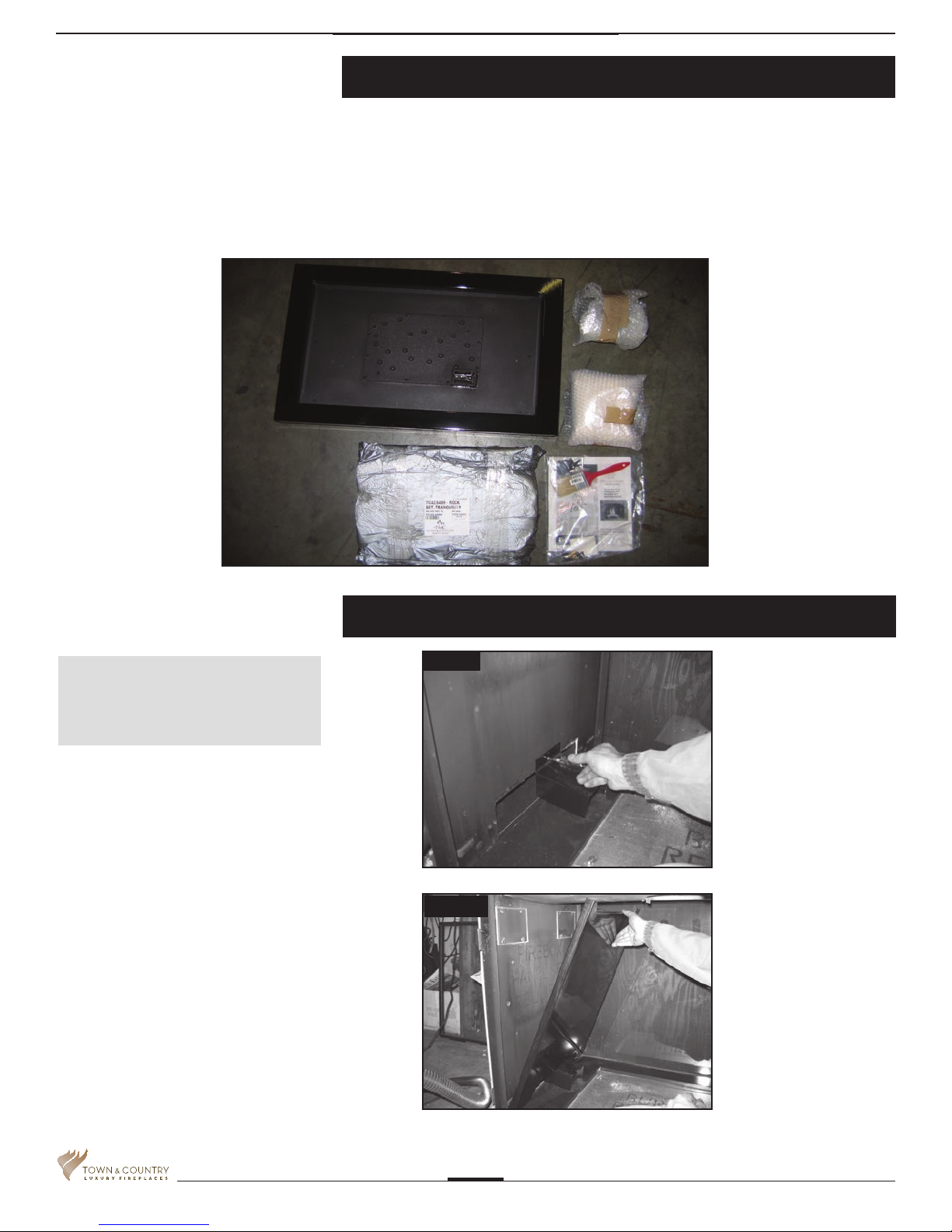
Package Contents
5 lbs. Sand 5096.9935
1 Bag tapered plugs TC36.503152
1 Burner assembly TC36.9410
2 Line covers TC36.9699PBKA
1 Pebble assembly TC42.9499
1 Instruction pack 5056.42801.C4
In these instructions the right and left sides
of the replace are referenced during the
installation process. The right side has the
control access cover in it.
1. Place base panels onto unit floor.
2. Attach a line cover to the left side of
rebox using screw from top center of
air channel. (Fig #1)
3. Remove panel retainer clips from the top
heat shield. Install left porcelain panel.
(Fig #2)
Tranquility Burner Installation
Fig #1
Fig #2
TC36ST_NGST04D_091014-16
2
Tranquility Burner Installation
If converting to propane see
conversion instructions on page #9
before proceeding.
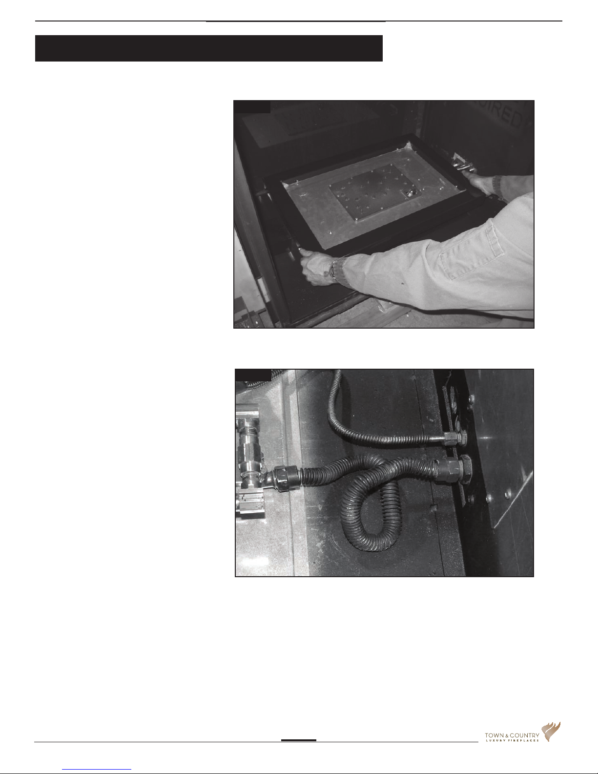
Set shutter according to fuel used. Fully
open for propane, closed for natural gas.
4. Place burner assembly into center of
porcelain base panels. (Fig #3)
5. Attach fuel ex lines to bulkhead ttings.
(Fig #4)
CAUTION: Ensure that all
connections are gas tight.
Fig #3
Fig #4
TC36ST_NGST04D_091014-16
3
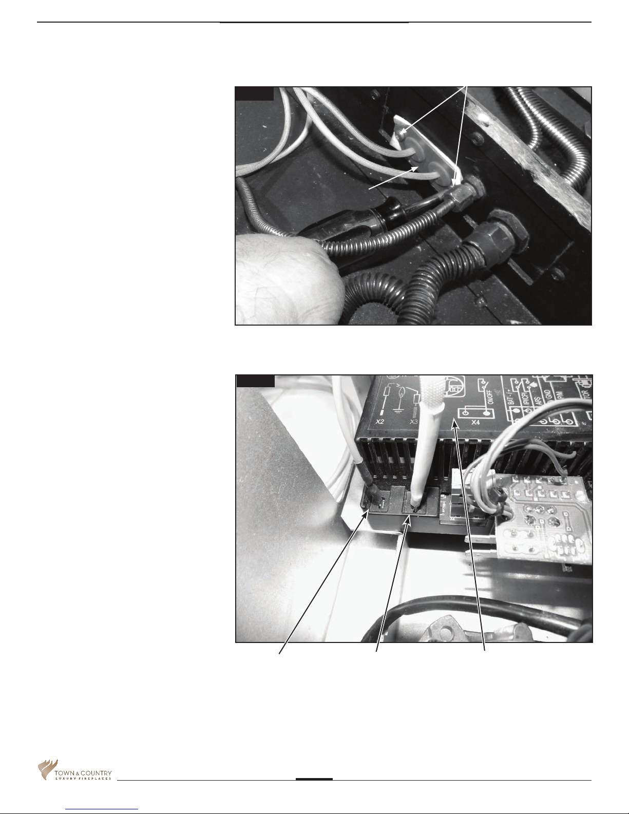
6. Secure the electrical bulkhead plate and
gasket to the rebox. (2 screws) Attach the
ignition and sensor wires to the module.
Red end to the connector marked by
the red dot, white end to the connector
marked by the white dot(Fig. #5 & 6)
2 SCREWS
Fig #5
BULKHEAD PLATE
Fig #6
IGNITION WIRE
(RED)
FLAME SENSOR
WIRE (WHITE)
INTERFACE MODULE
TC36ST_NGST04D_091014-16
4
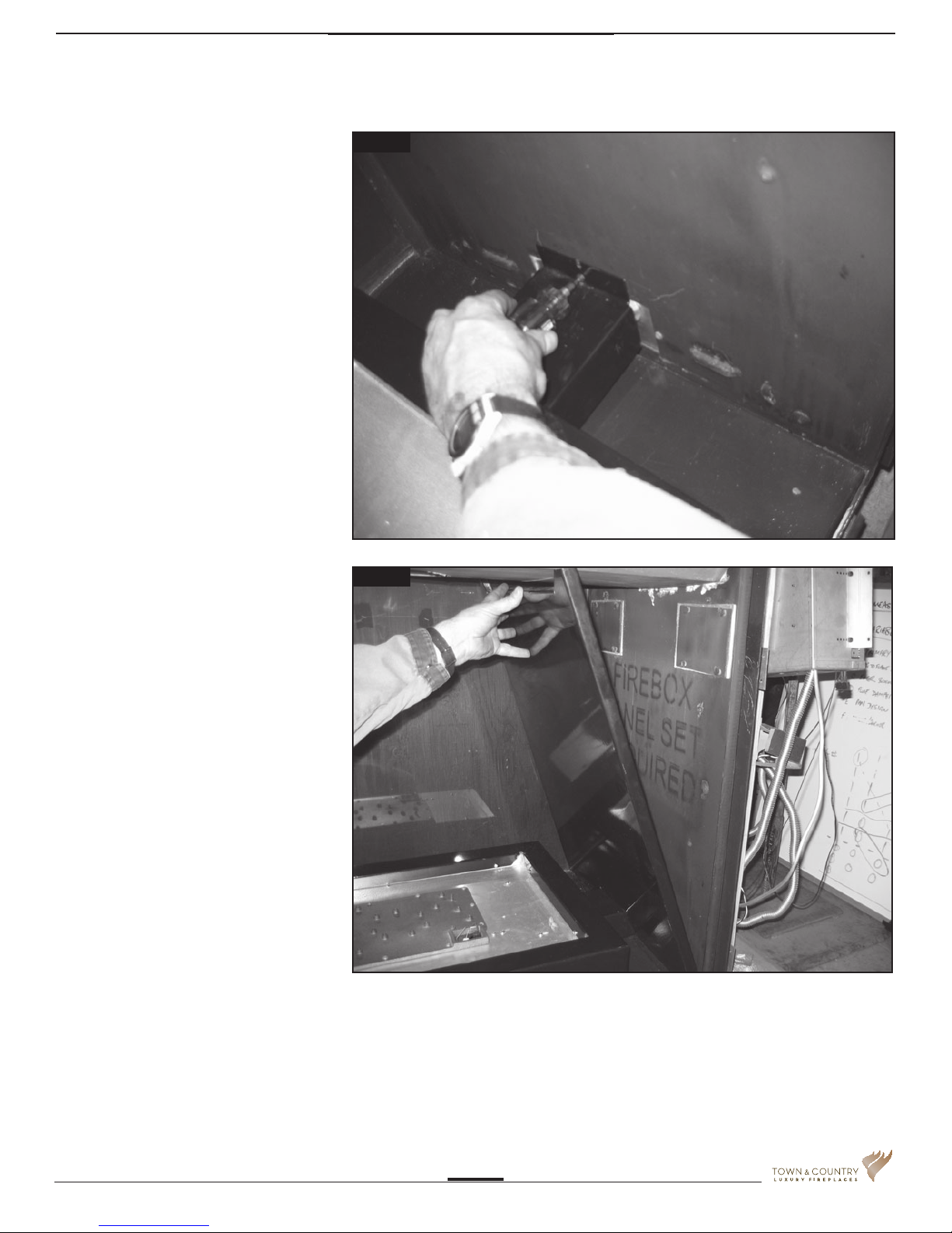
7. Place second line cover over lines and
attach to right side of rebox using top
bulkhead screw. (Fig #7)
8. Install right porcelain panel and re-install
panel retainer clips. (Fig #8)
Fig #7
Fig #8
TC36ST_NGST04D_091014-16
5
 Loading...