

Town & Country Fireplaces TC36ST, TC36.NGST07CA, TC36.NGST07CB, TC36.NGST07CC Instructions Manual
IMPORTANT:
THESE INSTRUCTIONS ARE TO REMAIN
WITH THE HOMEOWNER
These instructions are supplementary to the Installation
and Operating Instructions supplied with the replace
and should be kept together. Refer to the Installation
and Operating Instructions for proper gas supply, safety
requirements and operating instructions.
TC36 SEE-THRU
LODGEWOOD
BURNER AND
PANEL KIT
INSTRUCTIONS
PART# TC36.NGST07CA
TC36.NGST07CB
010611-20 TC36.NGST07C 5056.42801C7
TC36.NGST07CC
FOR MODEL: TC36ST
SERIES: C
Package Contents
• TC36.NGST07CA - EMBER BED/BURNER & GRATE ASSEMBLY
• TC36.NGST07CB - 6 PCS LOG SET
• TC36.NGST07CC - FLOOR, END CAPS & SIDE PANEL SET
NOTE: If unit is to be converted to Propane, see Propane conversion instructions
on page 13 before proceeding.
The air shutters on the burner control the primary combustion air to the gas burner and are pre-set to 1/8” open at the factory for
natural gas fuel. Some adjustment may be necessary to obtain desired ame and to eliminate carbon deposits.
Burner/Grate
Installation
In these instructions the right and left sides
of the replace are referenced during the
installation process. The right side of the
unit has the control access cover in it.
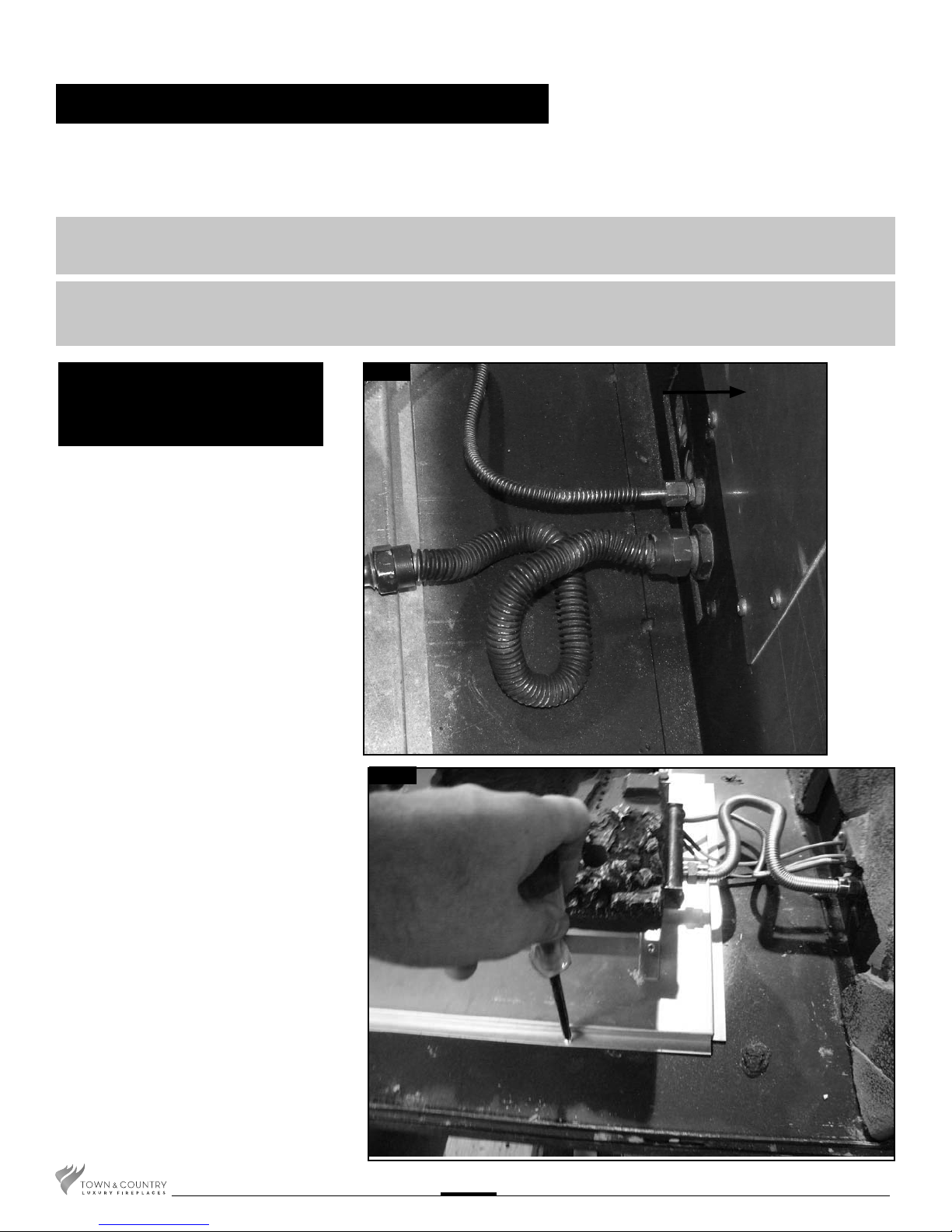
1. Connect the ex hoses from the pilot and
the main burner supply to the bulkhead
ttings on the rebox(Fig. # 1).
2. Attach the burner/grate assembly to the oor
of the rebox with four screws(Fig. # 2).
Fig. # 1
Fig. # 2
VALVE THIS SIDE
TC36.NGST07C 010611-20
2
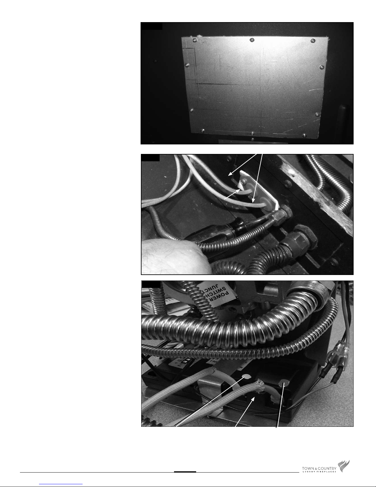
3. Remove access cover from side of
rebox(Fig. #3).
Fig. # 3
4. Secure the electrical bulkhead plate and
gasket to the rebox. (2 X #8 SMS screws)
Attach the ignition and sensor wires to the
module. Red end to the connector marked
by the red dot, white end to the connector
marked by the white dot (Fig. # 4 & 5).
2 SCREWS
Fig. # 4
BULKHEAD PLATE
Fig. # 5
5. Replace access cover and gasket.
TC36.NGST07C 010611-20
WHITE END TO
WHITE DOT
3
MODULE
RED END TO
RED DOT
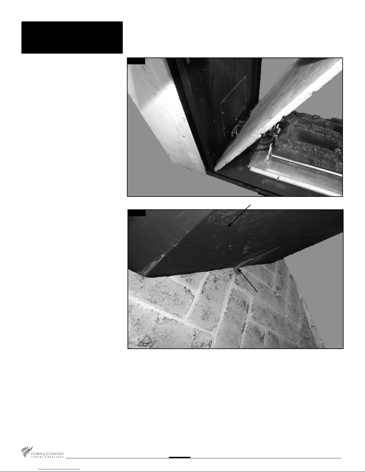
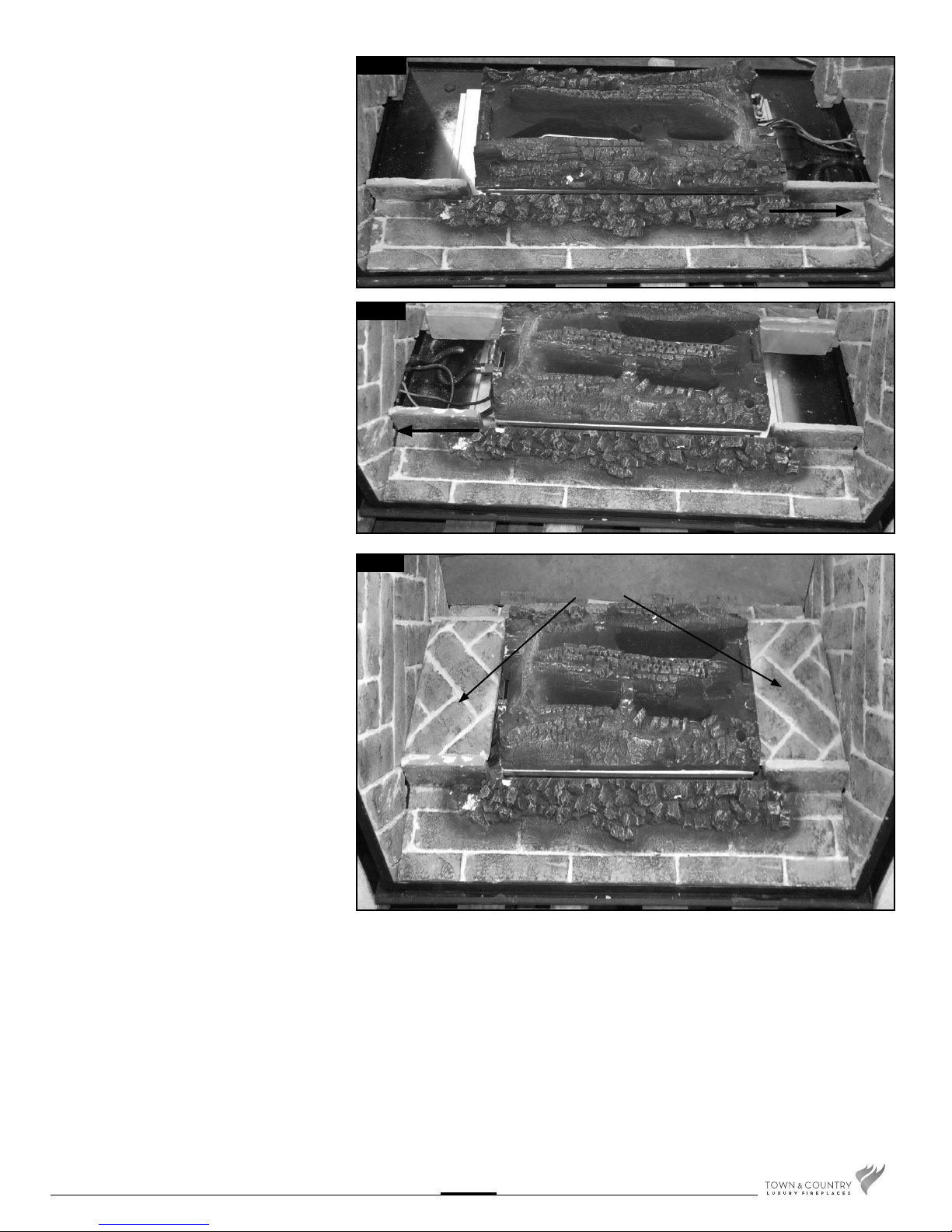
Panel
Installation
1. Remove panel retainer clips, one on
each side of the rebox. Insert bottom
of valve side panel and tilt up into place
then reinstall panel retainer clip(Fig. # 6
& 7). Repeat on opposite side.
Fig. # 6
TOP OF UNIT
Fig. # 7
PANEL RETAINER
TC36.NGST07C 010611-20
4
VALVE THIS SIDE
2. Install the oor panels as shown
VALVE THIS SIDE
(Fig. # 8 & 9).
Fig. # 8
Fig. # 9
VALVE THIS SIDE
VALVE THIS SIDE
3. Install the oor panel end caps over the gas
connections and the air intake (Fig. # 10).
Fig. # 10
FLOOR PANEL
END CAPS
TC36.NGST07C 010611-20
5
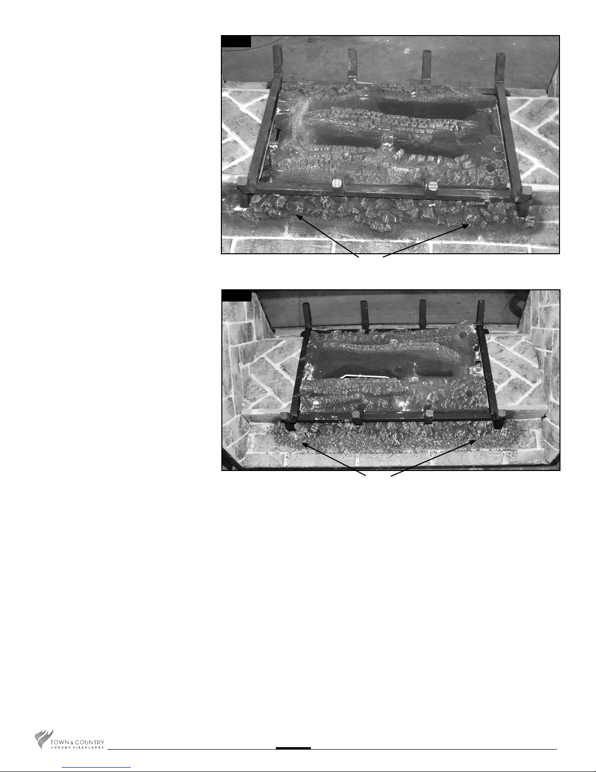
4. Install the log grate as shown (Fig. #11).
Fig. # 11
EMBER EDGE
5. Spread the black vermiculite evenly along
the edge of the embers on both sides as
shown (Fig. #11 & #12).
Fig. # 12
BLACK VERMICULITE
TC36.NGST07C 010611-20
6
 Loading...