

Town & Country Fireplaces TC36.NGST03C Installation Instructions Manual

INSTALLER: Leave this manual with the appliance.
CONSUMER: Retain this manual for future reference.
These instructions are supplementary to the Installation
and Operating Instructions supplied with the replace
and should be kept together. Refer to the Installation
and Operating Instructions for proper gas supply, safety
requirements and operating instructions
TC36 See-Thru
BLACK DIAMOND
BURNER KIT
0 31111-20 TC36.NGST03C 5056.42801C3
PART#TC36.NGST03C
FOR TC36
SEE-THRU
SERIES C
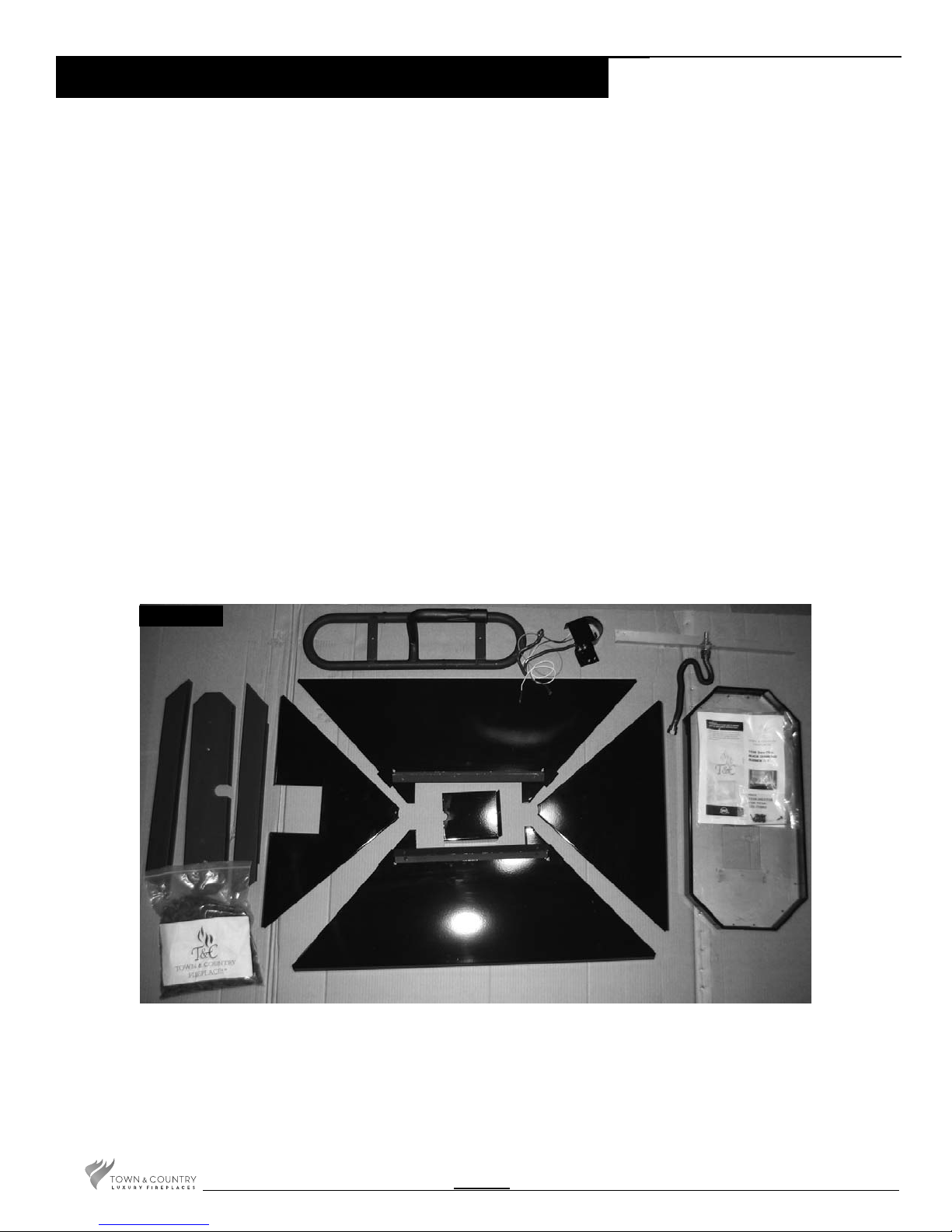
Package Contents
1 BURNER TUBE ................................................................................................TC36.50118398
1 SHUTTER CONTROL ROD .....................................................................................5002.9692
1 BURNER TRAY ASSEMBLY ................................................................................... TC36.9690
2 BURNER SHIELD, FRONT/REAR .................................................................. TC36.9693PBK
1 LEFT BURNER SHIELD .............................................................................. TC36.9693.2PBK
1 RIGHT BURNER SHIELD ............................................................................ TC36.9693.5PBK
1 LINE COVER .................................................................................................TC36.9699PBKA
1 PILOT SHIELD ................................................................................................ TC36.9626PBK
1 MANIFOLD ASSEMBLY .........................................................................................TC36.9692
2 MEDIA SPACER, FRONT/REAR ......................................................................................9695
1 MEDIA SPACER, CENTER ...............................................................................................9694
1 TUMBLED GLASS MEDIA .......................................................................................... 5012.01
1 HARDWARE PACKAGE ................................................................................... TC36.STHK03
1 PILOT ASSEMBLY .....................................................................................................5005.025
1 1/4” FLEX COMPRESSION ....................................................................................... 5019.225
1 1/2” FLEX FLARE CONNECTION ............................................................................. 5019.223
Fig. # 1
TC36.NGST03C 031111- 20
2
Black Diamond Burner Installation
NOTE: For the purposes of these
instructions the controls and gas
connections are on the right hand
side of the unit.
Remove porcelain panels if they
are installed.
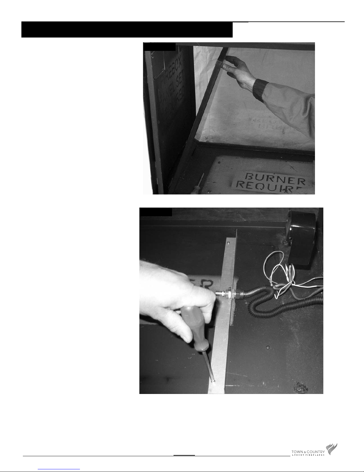
1. Remove the panel retainer clip
located on the upper heat shield, install
the left panel securing with panel retainer
clip previously removed. (Fig. #2)
Fig. # 2
Fig. # 3
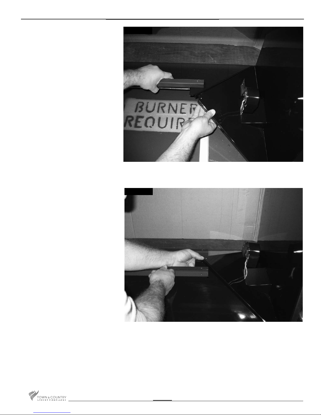
2. Attach the manifold assembly to the
oor of the rebox using two screws.
Seal the remaining holes in the oor
of the replace with screws. (Fig. #3).
3. Connect the manifold ex gas line
and pilot ex gas line to the bulkhead
ensuring a gas-tight connection.
TC36.NGST03C 031111-20
3
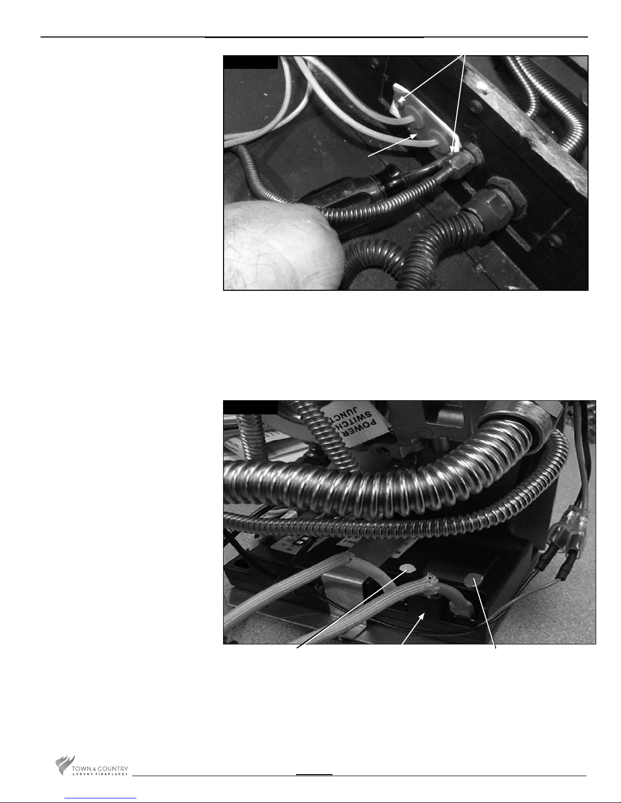
4. Secure the electrical bulkhead
plate and gasket to the rebox.
(2 screws) Attach the ignition and
sensor wires to the module. Red
end to the connector marked
by the red dot, white end to the
connector marked by the white
dot(Fig. #4 & 5)
NOTE: If converting to propane
refer to the propane
conversion section before
continuing. Pg. 12
2 SCREWS
Fig. # 4
BULKHEAD PLATE
Fig. # 5
WHITE END TO
WHITE DOT
MODULE
RED END TO
RED DOT
TC36.NGST03C 031111- 20
4
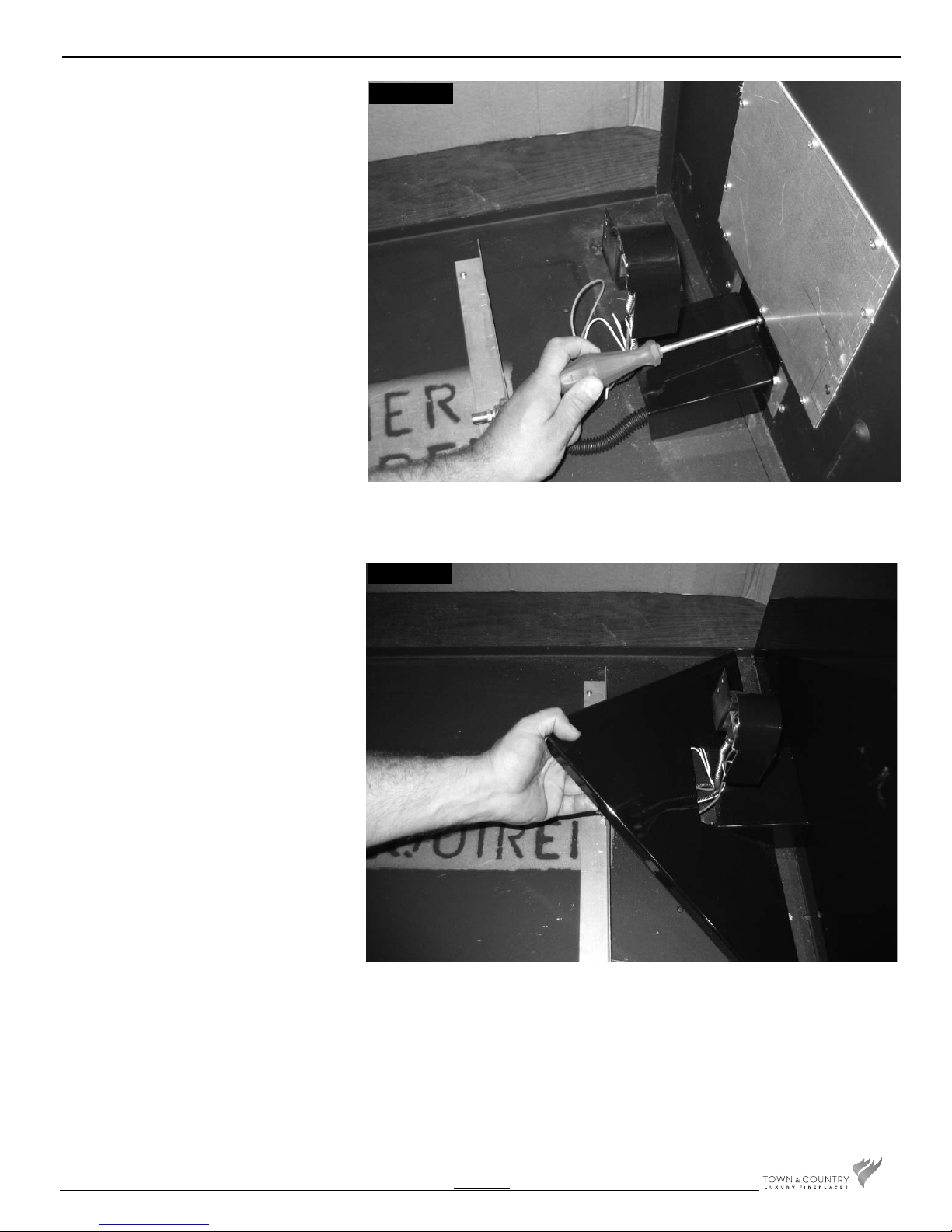
5. Attach the inlet cover using the top
screw of the bulkhead (Fig. #6).
Install the right porcelain panel (as in
Fig. #2).
Fig. # 6
6. Position the right burner shield over
the inlet cover ensuring that the pilot
assembly is protruding through the
half-hole between the inlet cover and
the right burner shield (Fig. #7).
Fig. # 7
TC36.NGST03C 031111-20
5
7. While supporting the right burner
shield install the rear burner shield,
resting the edge of the right burner
shield onto the support tab of the rear
burner shield (Fig. #8).
Fig. # 8
8. Install the front burner shield
positioning the support tab under the
right burner shield (Fig. #9).
Fig. # 9
TC36.NGST03C 031111- 20
6
 Loading...