

Town & Country Fireplaces TC36.NGST03 Installation Manual

210705-12 TC36.NGST03 5056.42801.3
TC36 See-Thru
BLACK DIAMOND
BURNER KIT
IMPORTANT:
THESE INSTRUCTIONS ARE TO REMAIN
WITH THE APPLIANCE INSTRUCTIONS
These instructions are supplementary to the Installation and
Operating Instructions supplied with the fireplace and should
be kept together. Refer to the Installation and Operating
Instructions for proper gas supply, safety requirements and
operating instructions.
PART#
TC36.NGST03
FOR TC36
SEE-THRU
2
210705-12 TC36.NGST03 5056.42801.3
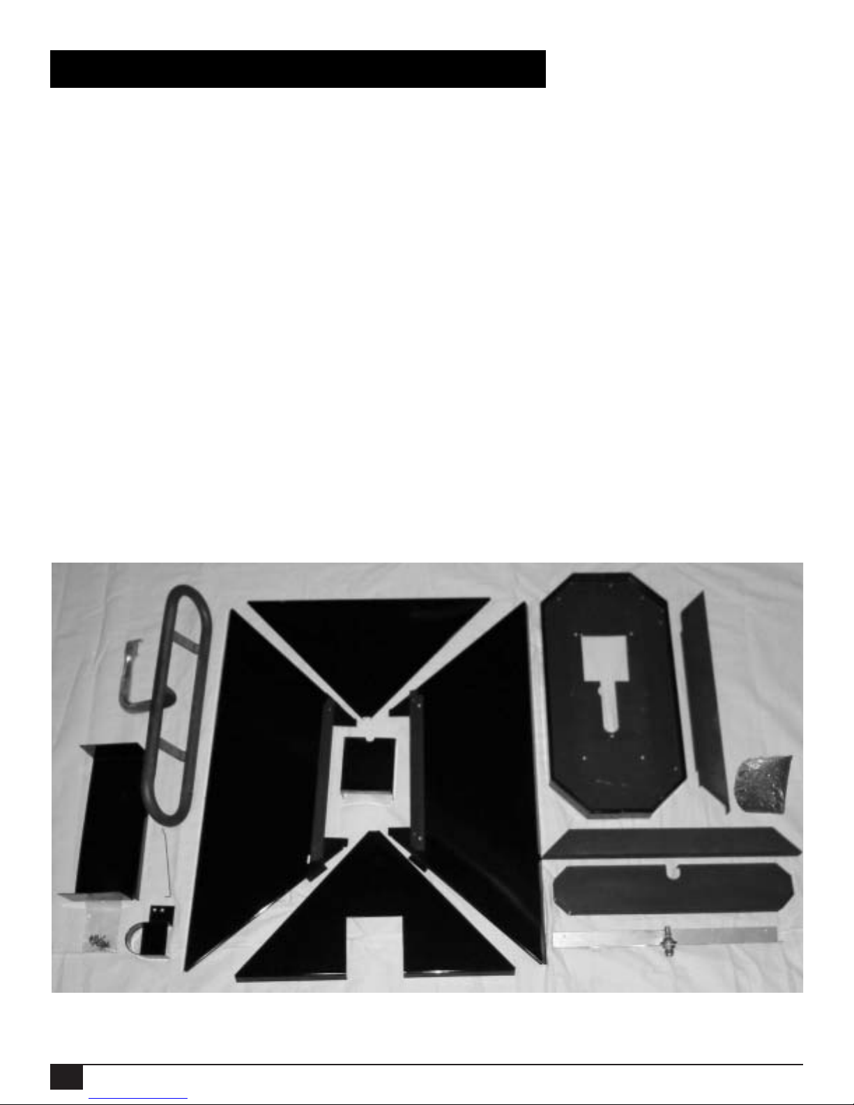
Package Contents
BURNER TUBE P ART# TC36.50118398
SHUTTER CONTROL ROD PART# 5002.9692
BURNER TRA Y ASSEMBL Y P ART# TC36.9690
2 BURNER SHIELD, FRONT/REAR PART# TC36.9693 PBK
LEFT BURNER SHIELD PART# TC36.9693.2 PBK
RIGHT BURNER SHIELD PART# TC36.9693.5 PBK
AIR CHANNEL INSERT PART# TC36.9697 PBK
INLET COVER PART# TC36.9699 PBK
PILOT SHIELD PART# TC36.9626.PBK
MANIFOLD ASSEMBLY PART# TC36.9692
2 MEDIA SPACER, FRONT/REAR PART# 9695
MEDIA SPACER, CENTER PART# 9694
TUMBLED GLASS MEDIA PART# 5012.01
HARDWARE PACKAGE PART# TC36.STHK03
Fig. #1
3
210705-12 TC36.NGST03 5056.42801.3
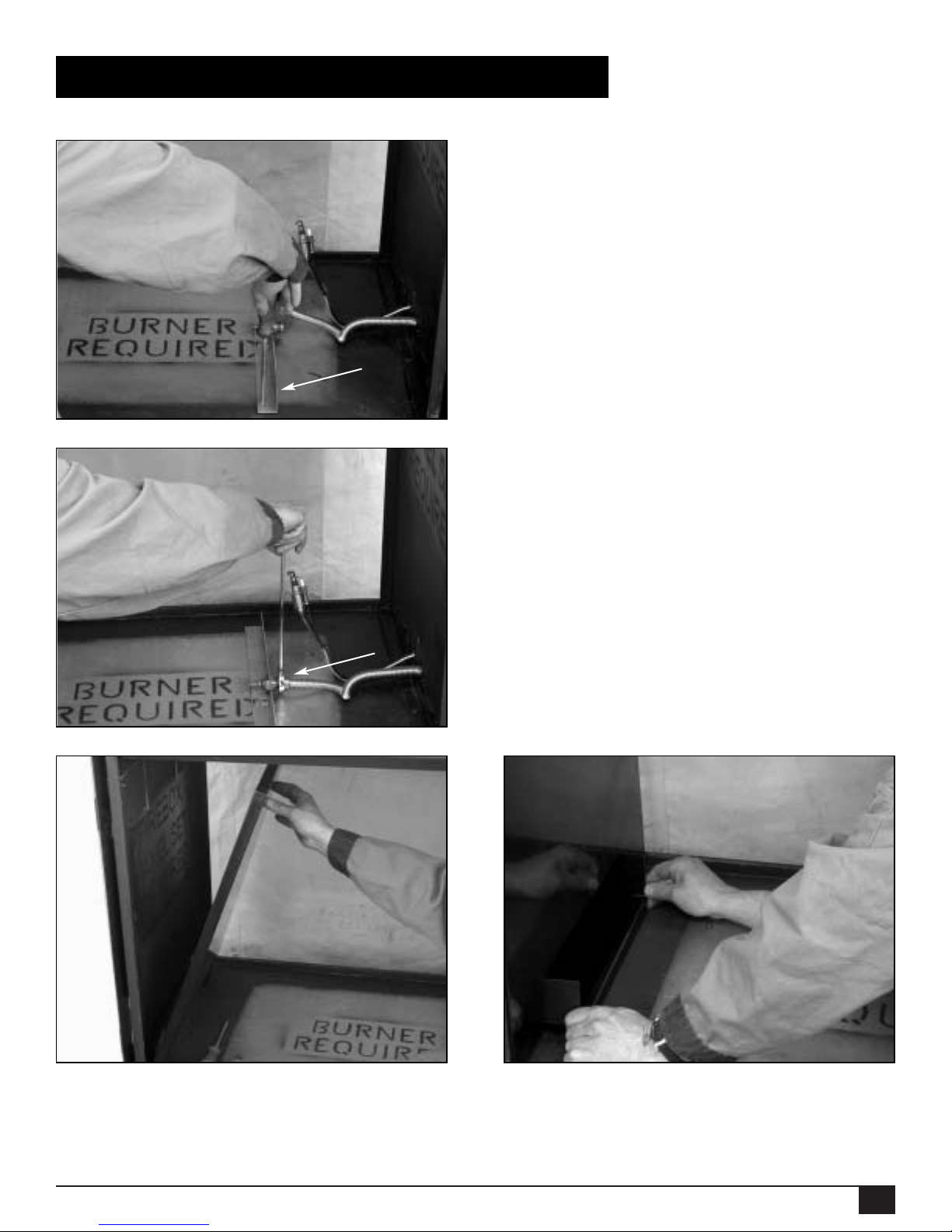
Black Diamond Burner Installation
1. Attach the manifold assembly to the
floor of the firebox using two screws.
(Fig. #2)
2. Connect the flex gas line to the
manifold ensuring a gas-tight
connection (Fig. #3).
3. If porcelain panels are not installed, install the left panel (Fig. #4) securing with panel retainer clip located on the
upper heat shield, and position the air channel insert into the air channel. (Fig. #5)
NOTE:The right side of the unit is the side with the control box inlet.
Fig. #2
Fig. #3
Fig. #4
Fig. #5
4
210705-12 TC36.NGST03 5056.42801.3
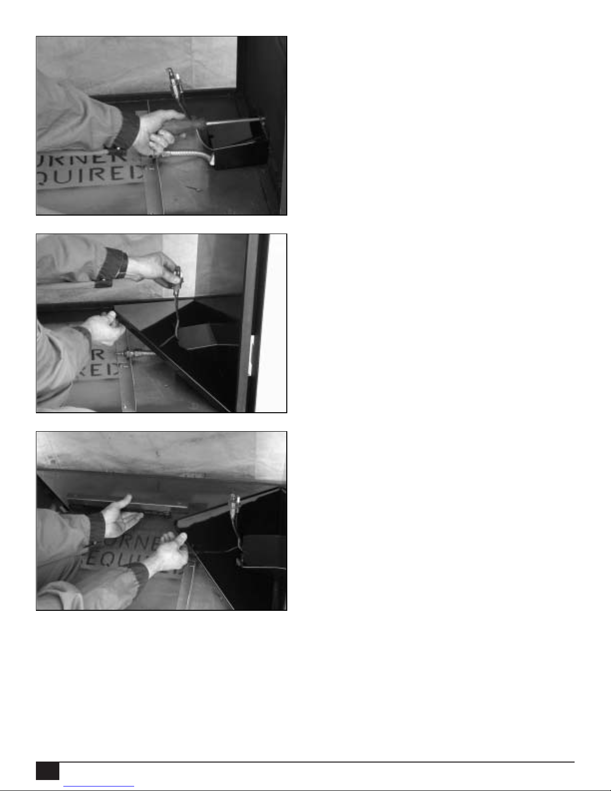
4. Attach the inlet cover using the top
two screws of the control inlet
(Fig. #6) and install the right porcelain
panel.
5. Position the right burner shield over
the inlet cover ensuring that the pilot
assembly is protruding though the
half-hole between the inlet cover and
the right burner shield (Fig. #7).
6. While supporting the right burner
shield,install the rear burner shield
resting the edge of the right burner
shield onto the support tab of the rear
burner shield (Fig. #8).
Fig. #6
Fig. #7
Fig. #8
 Loading...