

Town & Country Fireplaces TC36.NG04D Installation Instructions Manual

INSTALLER: Leave this manual with the appliance.
CONSUMER: Retain this manual for future reference.
These instructions are supplementary to the Installation and
Operating Instructions supplied with the replace and should be
kept together. Refer to the Installation and Operating Instructions for
proper gas supply, safety requirements and operating instructions.
TC36
TRANQUILITY
BURNER KIT
INSTRUCTIONS
Visit www.townandcountryfireplaces.net for the most recent version of this manual
240317-24 TC36_NG04D 5056.427D4
PART# TC36.NG04D
For TC36 Series D
Fireplaces
B
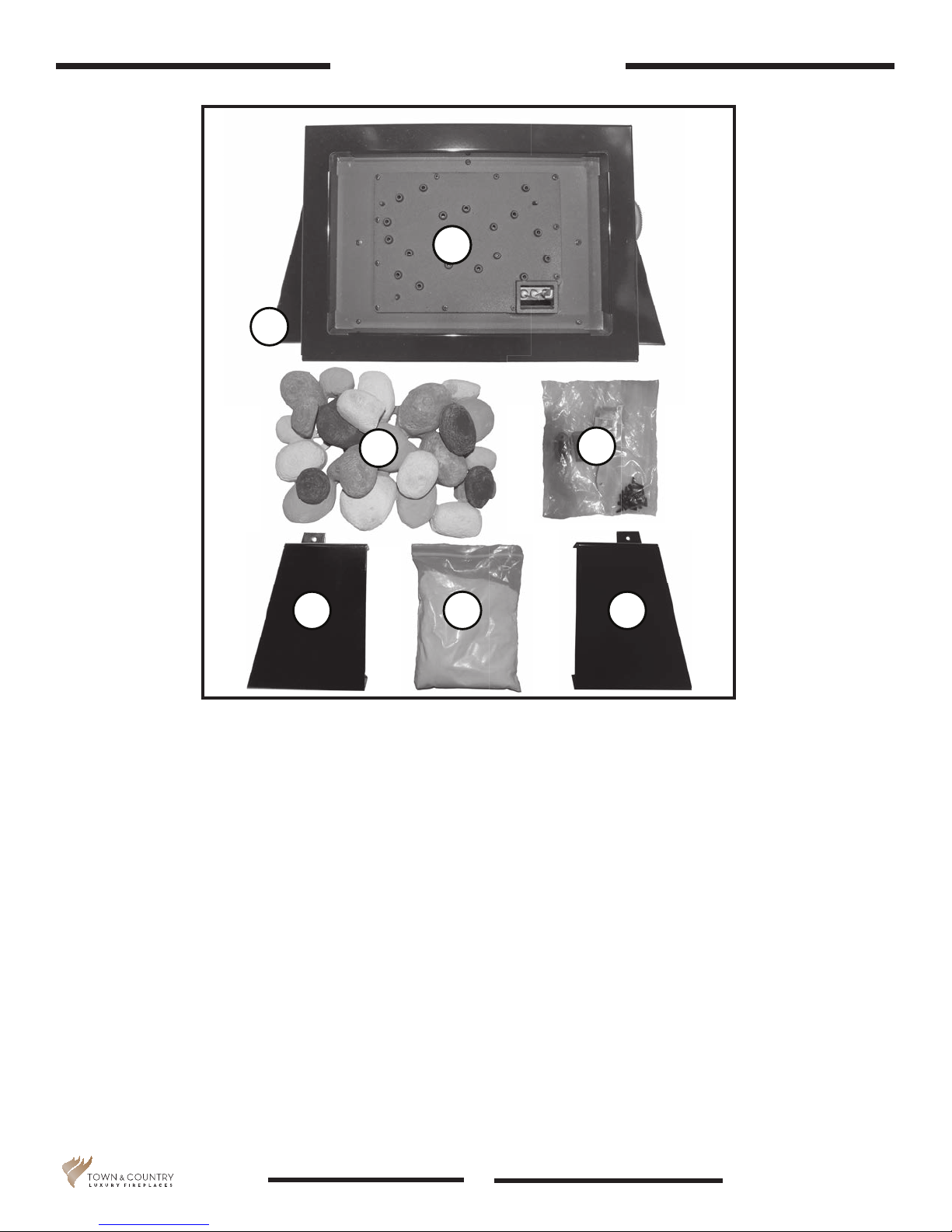
Contents of Package
A
A
C
E
Figure 1: TC36 Tranquility burner kit parts.
A. Burner assembly (including pilot & gas lines)
B. Panel, base (attached to burner assembly).
C. Pebble assembly
D. Hardware - tapered plugs, screws, brush, panel clips.
F
D
G
E. Side cover - left hand side.
F. 2.2 lbs Sand
G. Side cover (right hand side)
5056.427D4
2
TC36_NG04D 240317-24

Tranquility Burner Installation
If converting to propane see conversion instructions on page 15 before proceeding with
Tranquility Burner Kit.
Figure 2: Removing oor shield.
1. Remove oor shield (2 screws) and discard the shield. Use screws to plug vacant holes.
2. Plug any other vacant holes in the bottom of the rebox with 1/2” screws, as they are not
required to attach this style of burner (Figure 3).
Figure 3: 4 holes in replace oor to be plugged.
TC36_NG04D 240317-24 5056.427D4
3
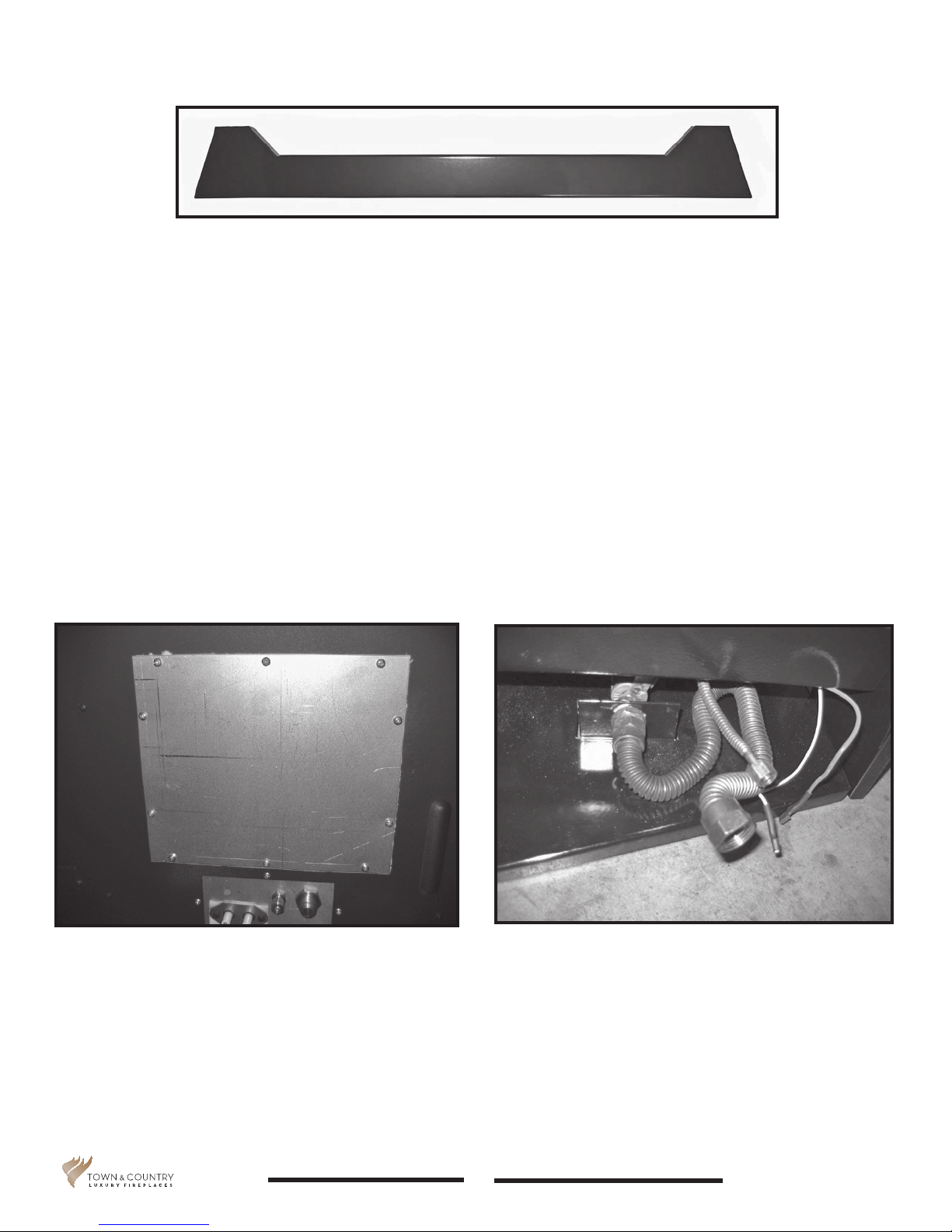
Figure 4: Base panel.
3. The base panel (Figure 4) is not used with the Tranquility burner kit and is a left over item to be
discarded.
4. Remove the 10 screws securing the access cover for the valve control center (Figure 5).
5. Bend the larger exible gas supply line, the smaller exible pilot gas line along with the ignition
and sensor wires into shape (Figure 6) so that the right hand side cover will t over top of them
before the burner is placed into the rebox (Figure 8). This cover must be positioned into the
burner before the burner is placed into the rebox as there is no room to install the cover once
the burner is in the rebox.
Figure 5: Access cover to valve control center.
5056.427D4
Figure 6: Flex line bent to shape.
4
TC36_NG04D 240317-24
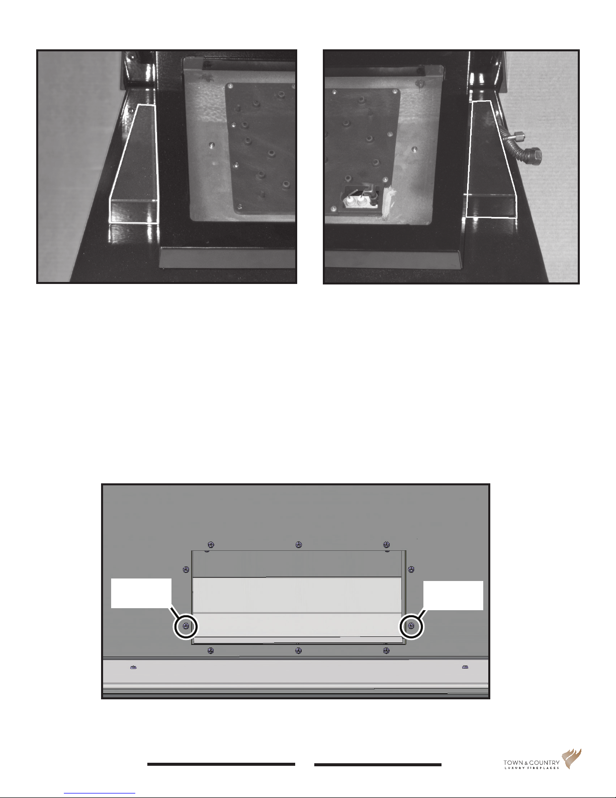
Figure 7: Left hand side cover.
Figure 8: Right hand side cover.
6. Place side covers between the burner tray and its base (Figure 7 and Figure 8) before the burner
tray is inserted into the rebox. These will remain in the retracted position until later in the installation process.
7. Remove the two lower outside screws from the Air Channel as indicated in Figure 9. The lower
panel will be attached to the rear wall of the rebox using the two screws just removed.
Remove this
screw
Figure 9: Air channel.
TC36_NG04D 240317-24 5056.427D4
Remove this
screw
5
Afx screw
here
Afx screw
here
Figure 11: Screw points for lower panel.
8. Mount the lower rear panel against the rear wall of the rebox and afx to the wall using the two
screws previously removed from the air channel (Figure 11).
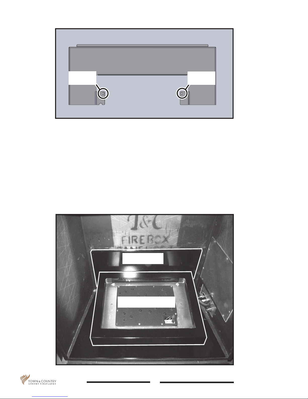
9. Position the burner tray assembly into the rebox and against the lower rear panel (Figure 10).
Figure 10: Lower rear panel and burner assembly.
5056.427D4
Rear panel
Burner assembly
6
TC36_NG04D 240317-24
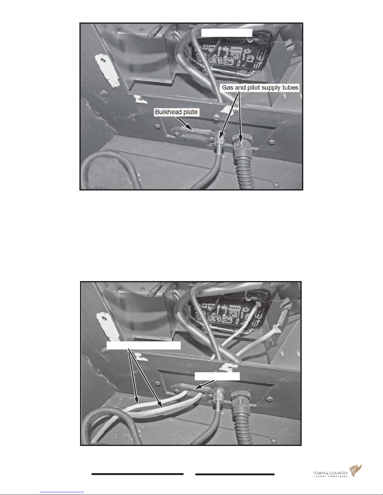
Figure 12: Gas and pilot supply tubes.
Interface module
10. Attach the main gas supply line and the pilot gas supply line to the bulk head ttings and tighten
(Figure 12). Ensure that there are no leaks.
11. Feed the ignition and sensor wires through the bulkhead plate and gasket to the rebox
(Figure 13).
Ignition and sensor wires
Bulkhead plate
Figure 13: Ignition and sensor wires routing.
TC36_NG04D 240317-24 5056.427D4
7
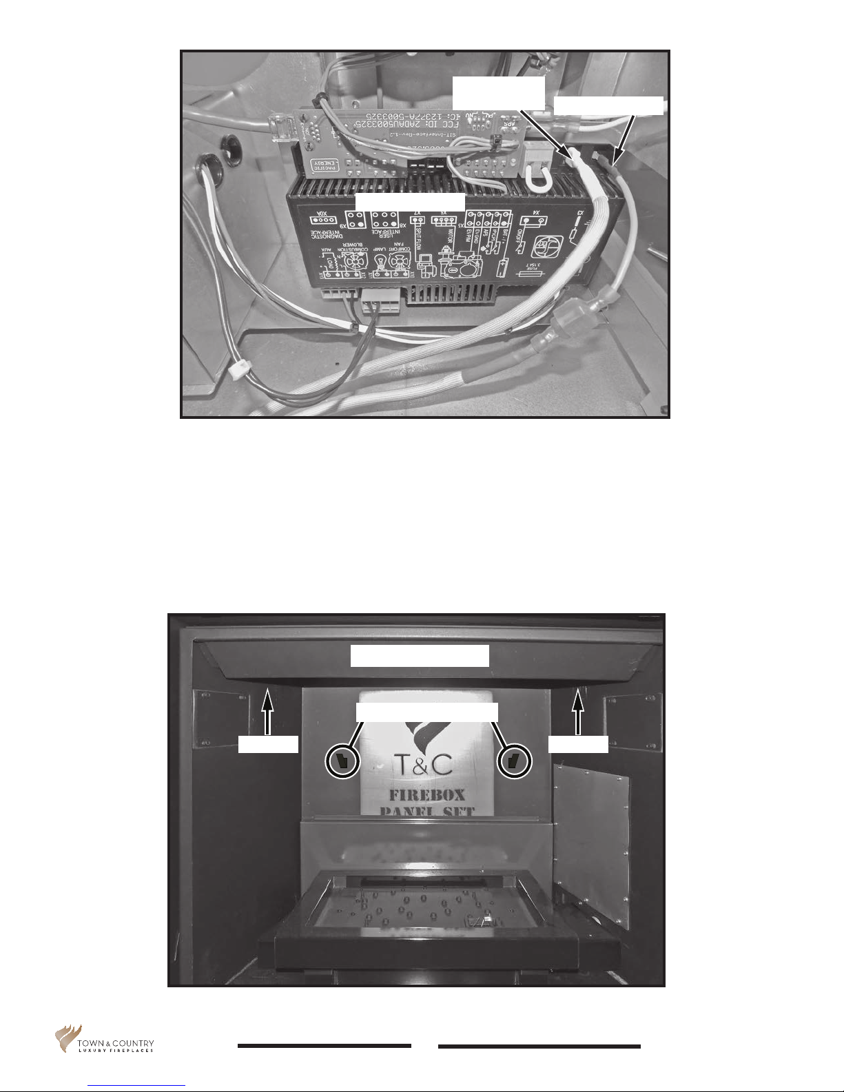
Flame sensor
wire (white)
Interface module
Ignition wire (red)
Figure 14: Interface module.
12. Attach the ignition and sensor wires to the interface module as indicated in Figure 14.
13. Once the gas and electrical lines are connected to the bulkhead and the interface module, reinstall the valve control center’s access cover (Figure 5 on page 4). The panels are now ready
to be installed.
Panel retainer
Panel tension tabs
Screw Screw
Figure 15: Panel retainer and panel tension tabs location.
5056.427D4
8
TC36_NG04D 240317-24
 Loading...