

Town & Country Fireplaces TC36.NG04C Instructions Manual

IMPORTANT:
THESE INSTRUCTIONS ARE TO REMAIN
WITH THE HOMEOWNER
These instructions are supplementary to the Installation
and Operating Instructions supplied with the replace
and should be kept together. Refer to the Installation
and Operating Instructions for proper gas supply, safety
requirements and operating instructions.
TC36
TRANQUILITY
BURNER KIT
INSTRUCTIONS
290411-16 TC36.NG04C 5056.427C4
PART# TC36.NG04C
For TC36 Series C
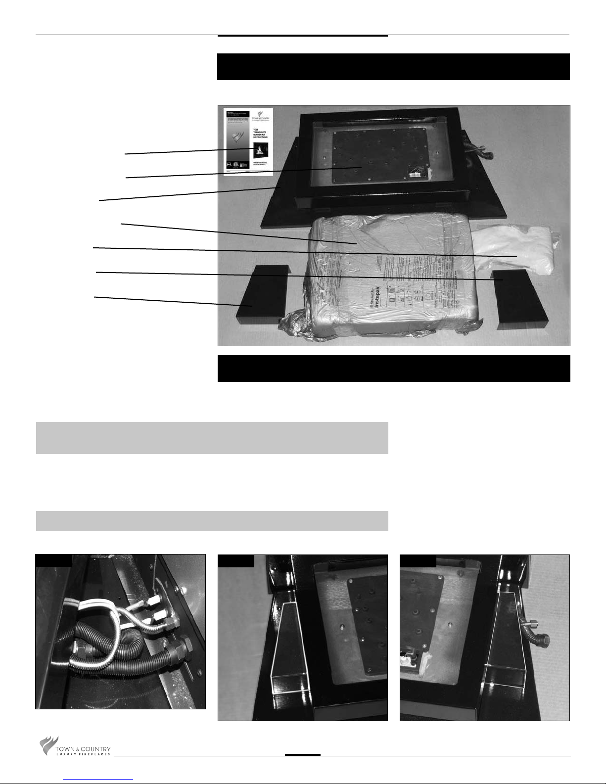
1 INSTRUCTION PACK
1 BURNER ASSEMBLY
1 PANEL, BASE
1 PEBBLE ASSEMBLY
2.2 LBS. SAND
1 COVER RHS
1 COVER LHS
1 BAG TAPERED PLUGS (NOT SHOWN)
Contents of Package
Tranquility Burner Installation
If converting to propane see conversion instructions on page #6
before proceeding.
NOTE: Plug the 4 vacant holes in the bottom of the rebox with 1/2” screws,
as they are not required to attach this style of burner.
1. Bend ex lines into the approximate shape. (Fig #1)
2. Place covers under the burner tray. (Fig #2a & 2b)
NOTE: Shutter must be fully closed for Natural gas, fully open for Propane.
Fig #1
Fig #2a
Fig #2b
TC36.NG04C 290411-16
2
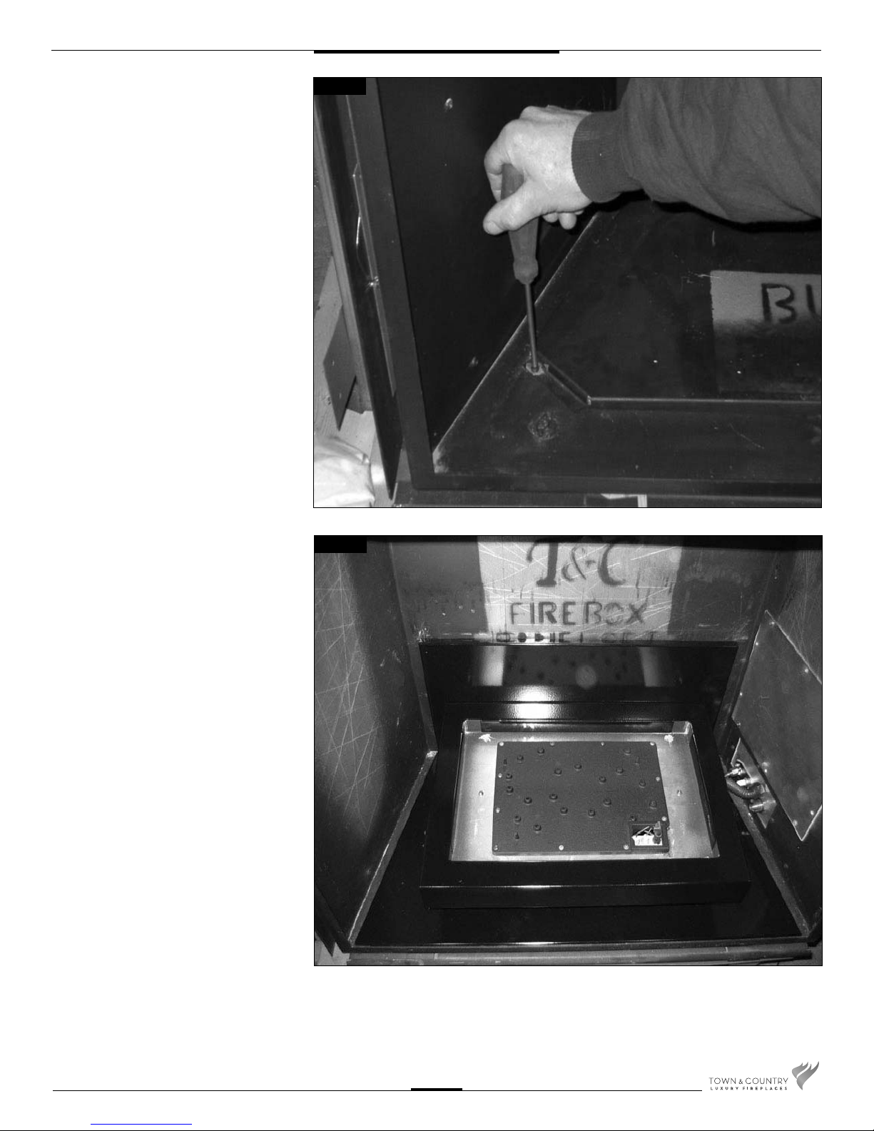
3. Remove oor shield (2 screws) and
discard. Replace screws to plug
vacant holes.
Fig #3
4. Remove the two screws from lower
sides of air channel. Install lower back
panel using the two screws previously
removed. Place burner assembly into
the rebox against the rear panel.
(Fig #4)
Fig #4
TC36.NG04C 290411-16
3
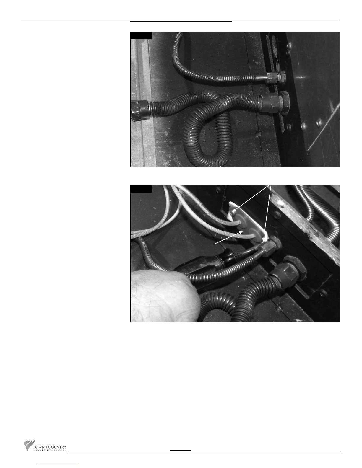
5. Attach fuel ex lines to bulkhead
ttings. (Fig. #5)
CAUTION:
Ensure that all connections are gas
tight.
Fig #5
2 SCREWS
Fig #6
6. Secure the electrical bulkhead plate and
gasket to the rebox. (2 screws) Attach the
ignition and sensor wires to the module.
Red end to the connector marked by
the red dot, white end to the connector
marked by the white dot(Fig. #6 & 7)
BULKHEAD PLATE
TC36.NG04C 290411-16
4
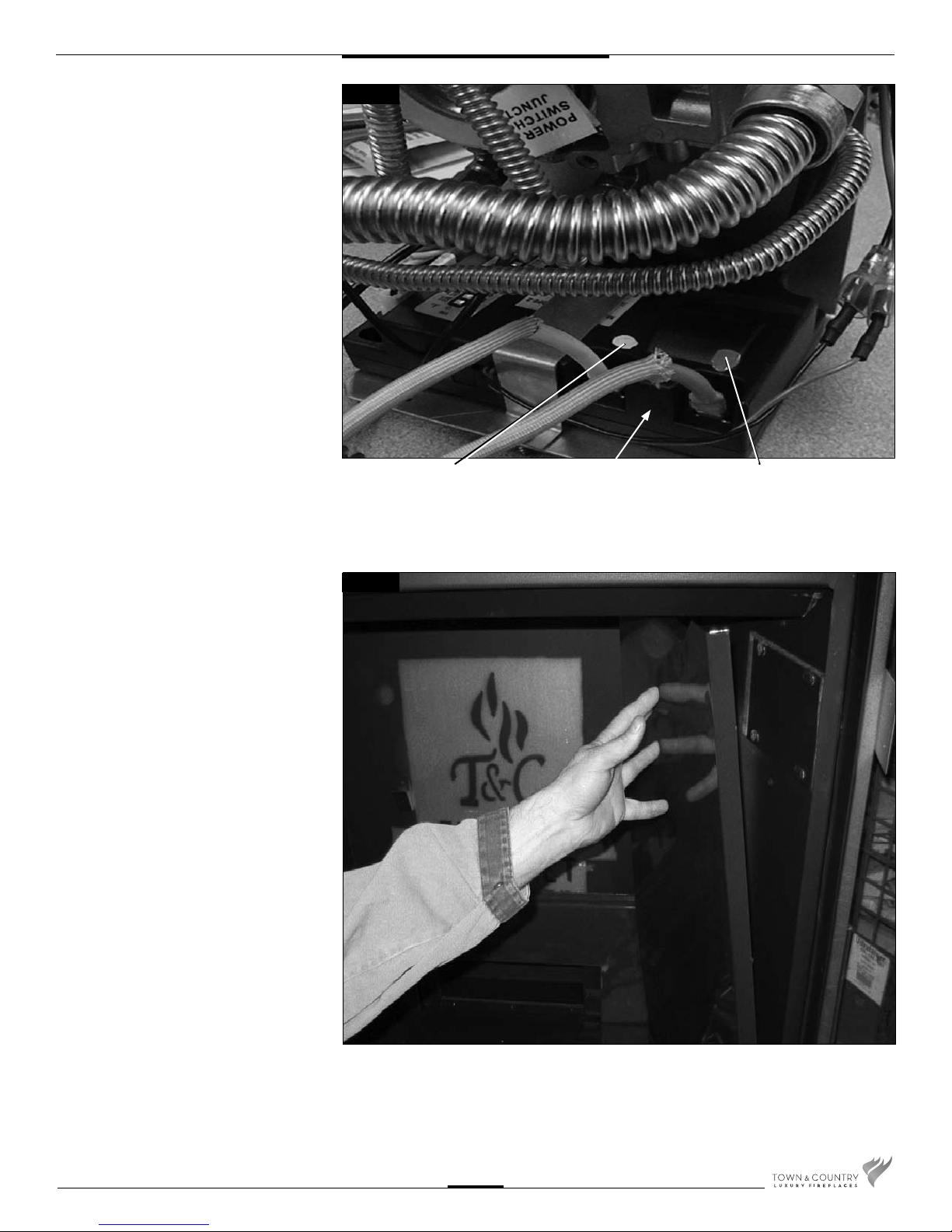
Fig #7
7. Remove panel retainer from upper heat
shield. Install right porcelain panel, tilting
in from front corner. (Fig #8)
WHITE END TO
WHITE DOT
Fig #8
MODULE
RED END TO
RED DOT
TC36.NG04C 290411-16
5
 Loading...