

Town & Country Fireplaces TC36.NG03D Installation Instructions Manual
INSTALLER: Leave this manual with the appliance.
CONSUMER: Retain this manual for future reference.
These instructions are supplementary to the Installation and
Operating Instructions supplied with the replace and should be
kept together. Refer to the Installation and Operating Instructions for
proper gas supply, safety requirements and operating instructions
TC36
BLACK DIAMOND
BURNER KIT
INSTRUCTIONS
Visit www.townandcountryfireplaces.net for the most recent version of this manual
140317-20 TC36_NG03D 5056.427C3
PART #TC36.NG03D
For TC36 & TC36 Arch
Series D Fireplaces
E
D
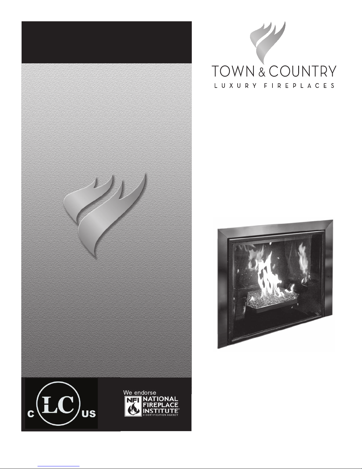
Package Contents
A. Burner Tube
B. Burner Shield
C. Media Spacer, Rear
B
I
C
1A
H
G
F
D. Media Spacer, Center
E. Media Spacer, Front
F. 5lbs. Tumbled Glass
G. Burner Tray
H. Pilot Shield (including pilot and
supply tube).
I. Manifold Assembly
Hardware Package (not shown)
Figure 1: Black diamond burner kit parts.
NOTE: MUST BE USED WITH PORCELAIN PANEL SET PART# TCPN.757031.C
Burner Installation
NOTE:
If converting to propane, refer to
the propane conversion section
on page 13 before continuing.
A porcelain panel set must be used
in conjunction with the installation
of the burner assembly.
NOTE: The burner shield may
need to be loosened and retightned after positioning if the
panel does not slip in behind it.
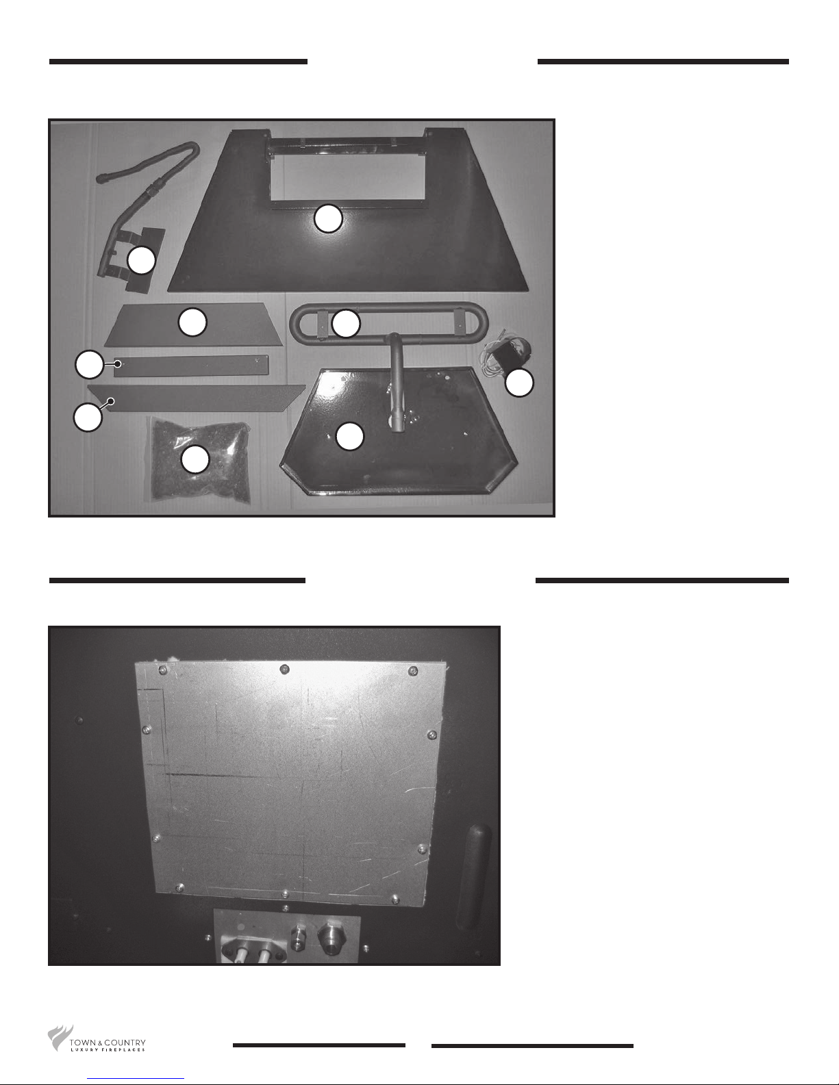
1. Remove access cover from
the valve control center at the
inside right hand side of the
rebox (Figure 2).
Figure 2: Access cover to valve control center.
5056.427C3
2
TC36_NG03D 140317-20
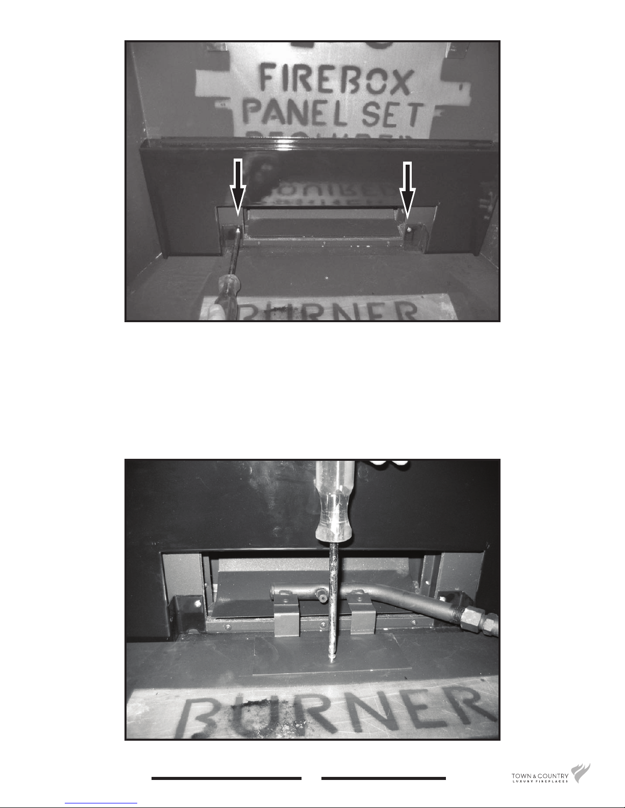
Figure 3: Removing screws from air channel.
2. Remove 2 screws from the air channel and attach the lower rear panel to the rebox with these
screws (Figure 3).
3. Attach the manifold bracket to the oor shield in the bottom of the rebox with one screw
(Figure 4).
Figure 4: Attaching manifold bracket.
TC36_NG03D 140317-20
3
5056.427C3
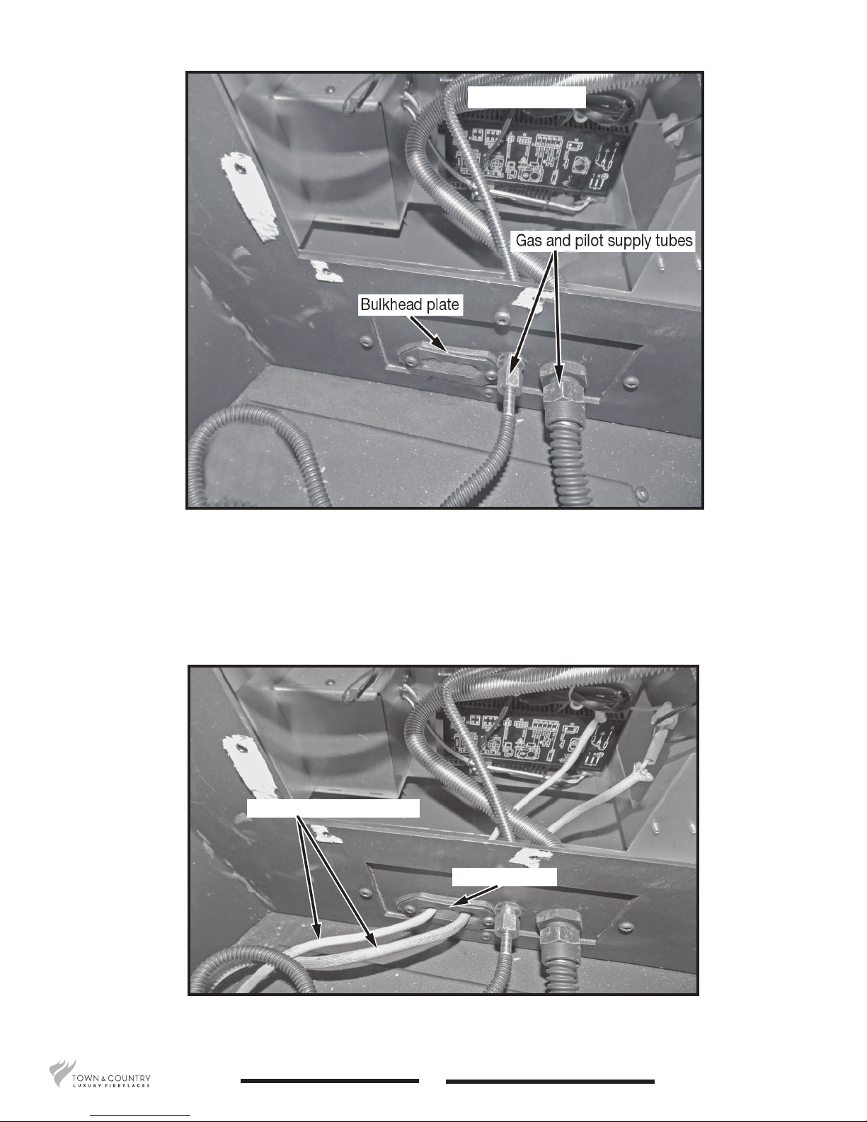
Interface module
Figure 5: Gas and pilot supply tubes.
4. Attach the manifold and pilot supply tubes to the bulk head tting and tighten (Figure 5). Ensure
that all connections are gas tight.
5. Feed the ignition and sensor wires through the bulkhead plate (Figure 6) to the interface module.
Ignition and sensor wires
Bulkhead plate
Figure 6: Ignition and sensor wires routing.
5056.427C3
4
TC36_NG03D 140317-20
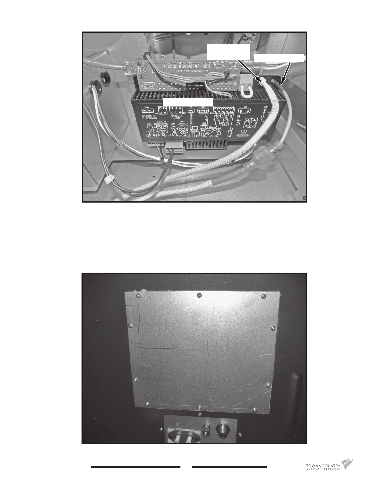
Figure 7: Interface module.
Interface module
Flame sensor
wire (white)
Ignition wire (red)
6. Attach the ignition and sensor wires to the interface module as shown in Figure 7.
7. Reinstall the valve control center access panel (Figure 8).
Figure 8: Re-install access cover to valve control center.
TC36_NG03D 140317-20
5
5056.427C3
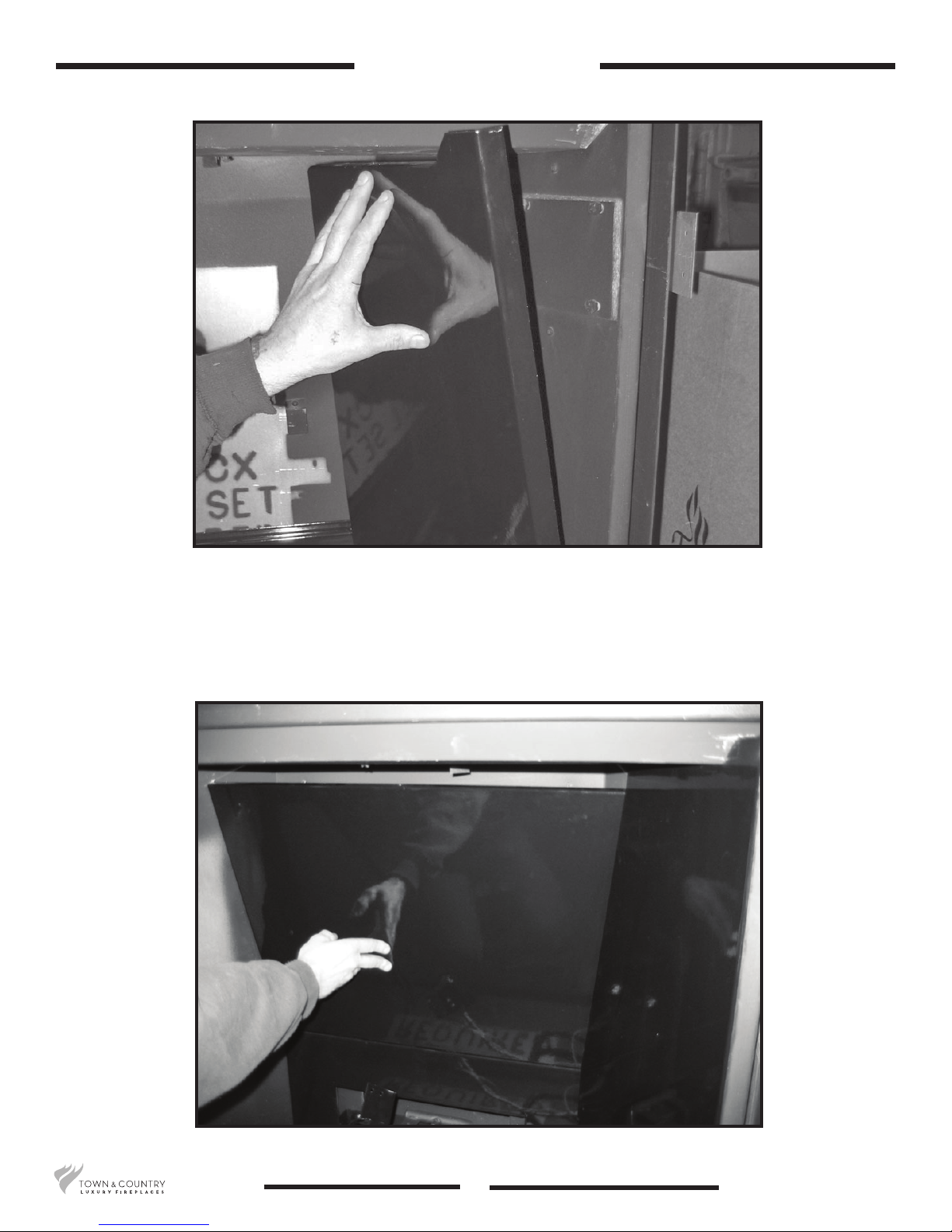
Panel Installation
Figure 9: Installing right side panel.
1. Remove panel retainer from the upper heat shield. Install right side panel by placing the bottom
into the rebox and tipping the top into position (Figure 9).
2. Position upper rear panel on top of lower rear panel and slip in behind the right panel (Figure 10).
Figure 10: Install upper rear panel.
5056.427C3
6
TC36_NG03D 140317-20
 Loading...