

Town & Country Fireplaces TC36.NG03C Instructions Manual
INSTALLER: Leave this manual with the appliance.
CONSUMER: Retain this manual for future reference.
These instructions are supplementary to the Installation and
Operating Instructions supplied with the replace and should be
kept together. Refer to the Installation and Operating Instructions
for proper gas supply, safety requirements and operating
instructions
TC36
BLACK DIAMOND
BURNER KIT
INSTRUCTIONS
290411-20 TC36.NG03C 5056.427C3
PART #TC36.NG03C
For use with:
Model: TC36
Series: C
Package Contents
• BURNER TUBE
• MEDIA SPACER, Rear
• BURNER TRAY ASSY
• MEDIA SPACER, Front
• 5 lbs. TUMBLED GLASS
• MEDIA SPACER, Center
• BURNER SHIELD
• PANEL, LOWER REAR
• MANIFOLD ASSEMBLY
(including supply tube)
• PILOT SHIELD
(including pilot and supply tube)
• HARDWARE PACKAGE
NOTE: MUST BE USED WITH PORCELAIN PANEL SET PART# TCPN.757031.C
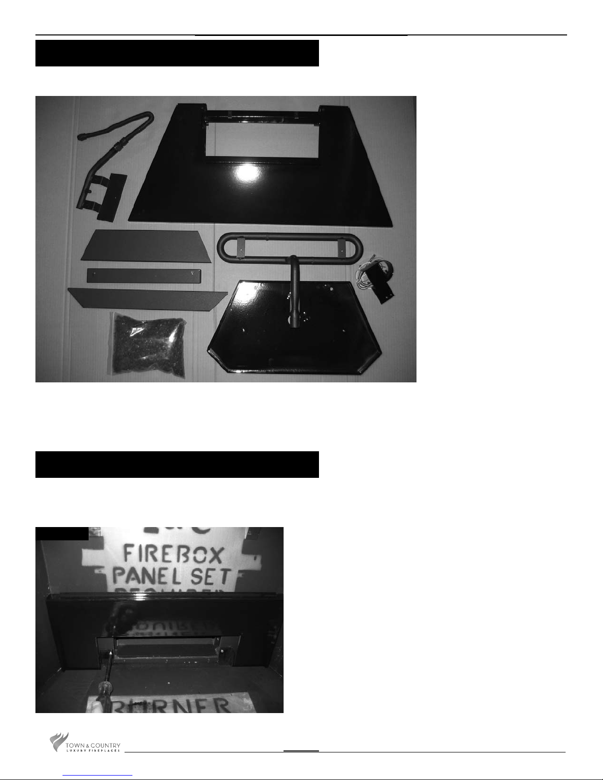
Burner Installation
Fig. # 1
A porcelain panel set must be used in conjunction with
the installation of the burner assembly.
1) Remove 2 screws from the air channel and attach the lower
rear panel to the rebox with these screws. (Fig. # 1)
NOTE: The burner shield may need to be loosened and
re-tightned after positioning if the panel does not slip in
behind it.
2
TC36.NG03C 290411-20
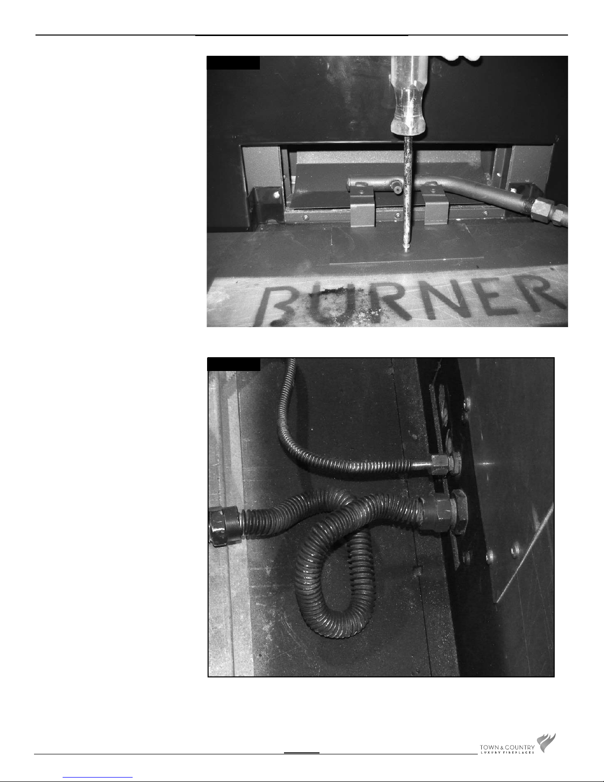
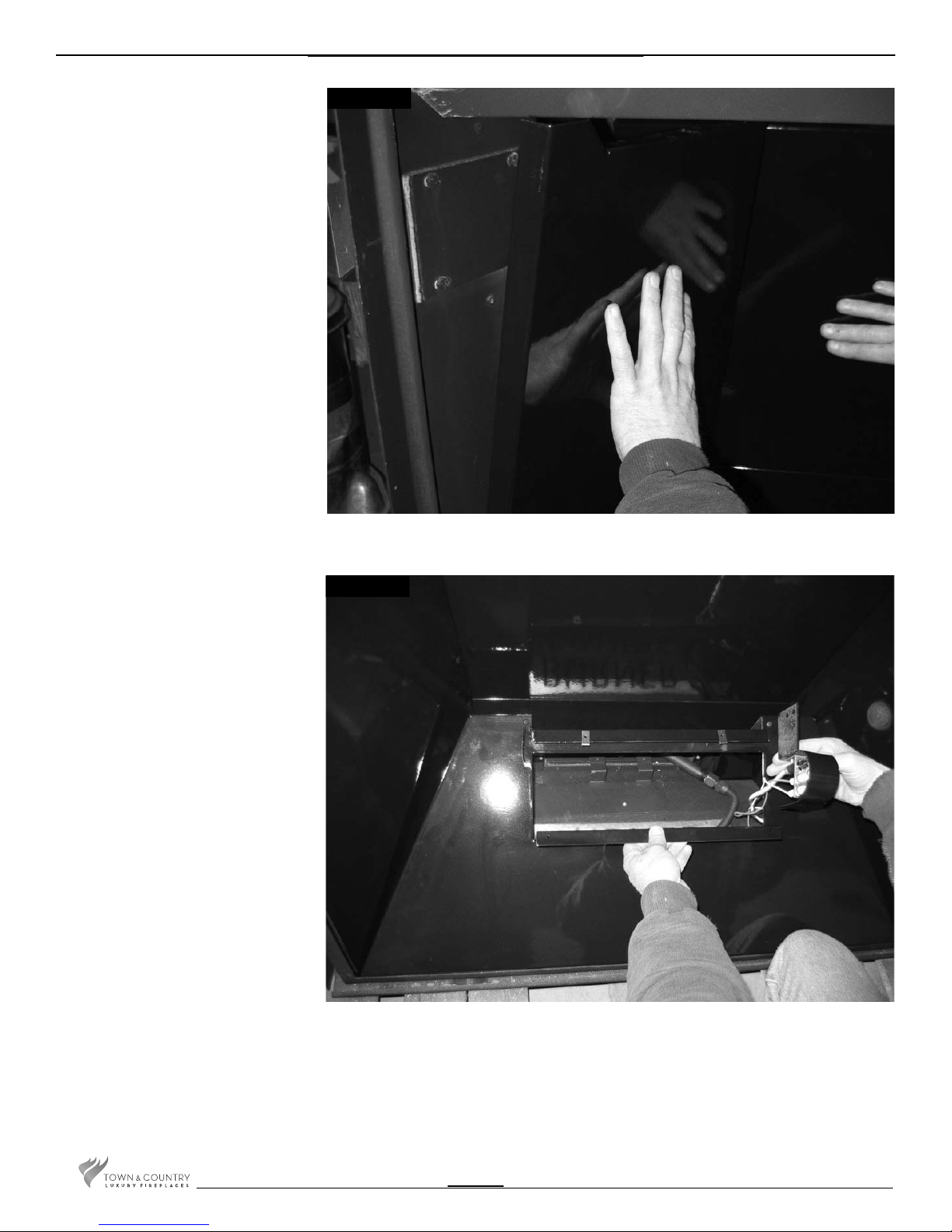
2) Attach the manifold bracket to the oor
shield in the bottom of the rebox with
one screw. (Fig. # 2)
Fig. # 2
3) Attach the manifold and pilot supply
tubes to the bulk head tting and
tighten. (Fig. # 3) Ensure that all
connections are gas tight.
Fig. # 3
TC36.NG03C 290411-20
3

4. Secure the electrical bulkhead plate and
gasket to the rebox. (2 screws) Attach the
ignition and sensor wires to the module.
Red end to the connector marked by
the red dot, white end to the connector
marked by the white dot(Fig. #4 & 5)
NOTE: If converting to propane refer to
the propane conversion section
before continuing. Pg. 12
2 SCREWS
Fig. # 4
BULKHEAD PLATE
Fig. # 5
WHITE END TO
WHITE DOT
MODULE
RED END TO
RED DOT
4
TC36.NG03C 290411-20
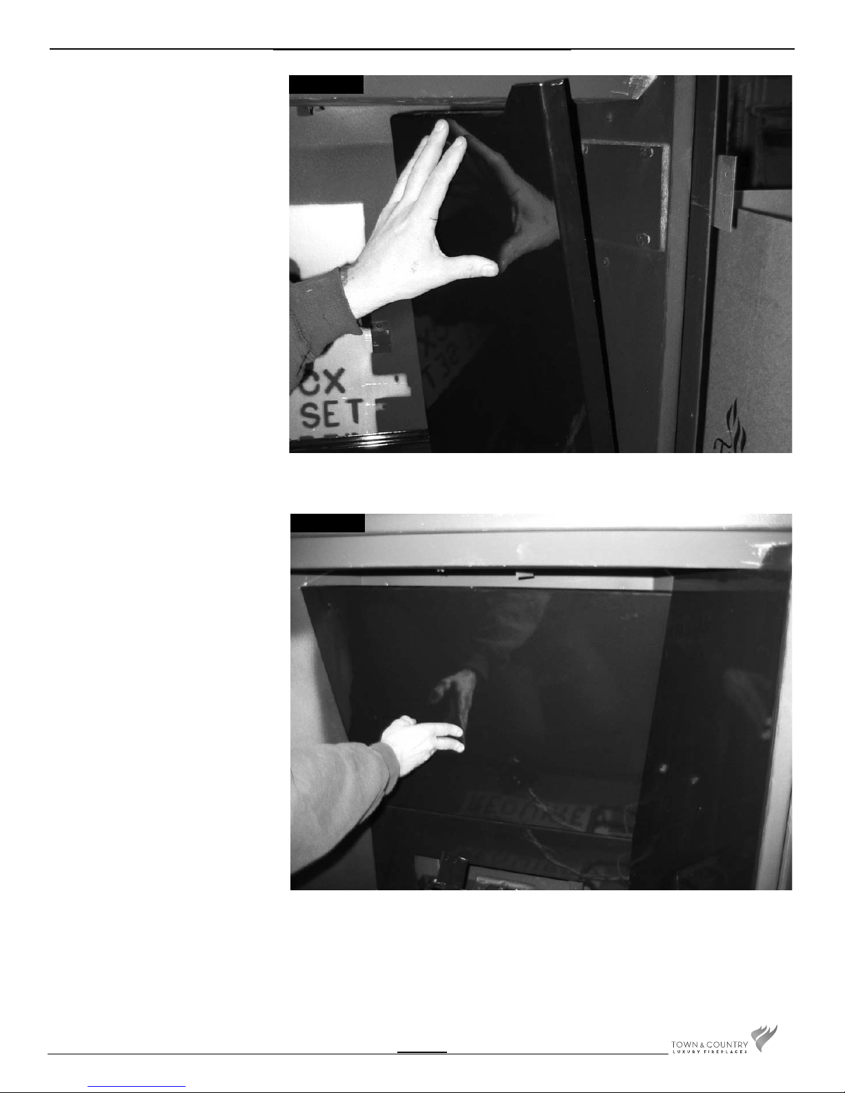
5) Remove panel retainer from the upper
heat shield. Install right side panel by
placing the bottom into the rebox
and tipping the top into position. (Fig.
# 6)
Fig. # 6
6) Position upper rear panel on top of
lower rear panel and slip in behind
the right panel. (Fig. # 7)
Fig. # 7
TC36.NG03C 290411-20
5
7) While supporting the upper rear panel
install the left side panel in the same
manner as the right side panel. Secure
both side panels with the previously
removed panel retainer. (Fig. # 8)
Fig. # 8
8) Install burner shield by tipping the
shield into the rebox, feed the pilot
assembly through the opening in the
shield. (Fig. # 9)
Fig. # 9
6
TC36.NG03C 290411-20
 Loading...