

Town & Country Fireplaces TC36.NG02DN Installation Instructions Manual

INSTALLER: Leave this manual with the appliance.
CONSUMER: Retain this manual for future reference.
These instructions are supplementary to the Installation and
Operating Instructions supplied with the replace and should be
kept together. Refer to the Installation and Operating Instructions for
proper gas supply, safety requirements and operating instructions
TC36
COUNTRY HOME
BURNER KIT
INSTRUCTIONS
(NATURAL GAS ONLY)
Visit www. townandcountryfireplaces.net for the most recent version of this manual
020317-16 TC36_NG02DN 5056.42702D
PART# TC36.NG02DN
For TC36 & TC36 Arch
Series D Fireplaces
7 Pcs Log Set
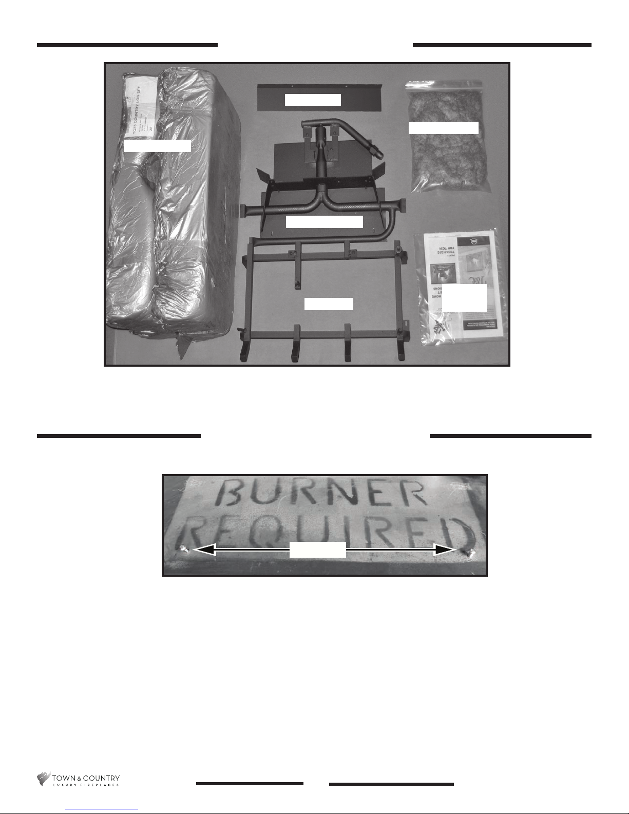
Contents of Package
Air Deector
Burner Assembly
Log Grate
Ember Material
Hardware
Package
Figure 1: TC36 and TC36 Arch Country home burner kit contents.
Burner/Grate Installation
Screws
Figure 2: Firebox base.
1. Place the keyhole slots of the burner (Figure 3) over the two screws located on the rebox oor
(Figure 2).
5056.42702D
2
TC36_NG02DN 020317-16
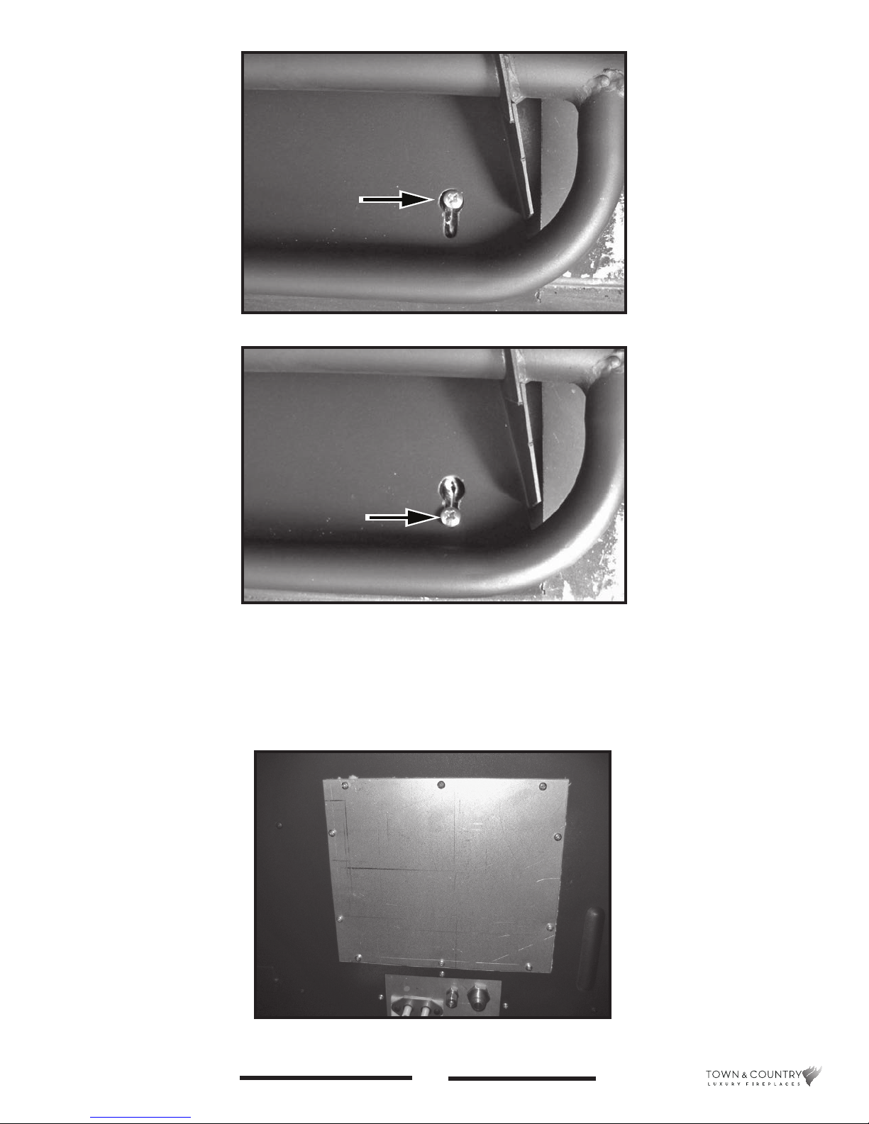
Figure 3: Burner assembly over top of right side screw.
Figure 4: Burner assembly pushed back against right
side screw.
2. Slide the burner back to engage the screws in the small part of the keyhole slot and tighten
screws (Figure 4).
3. Remove access cover to the vavle control center from right side of rebox (Figure 5)
Figure 5: Access cover to valve control center.
TC36_NG02DN 020317-16
3
5056.42702D
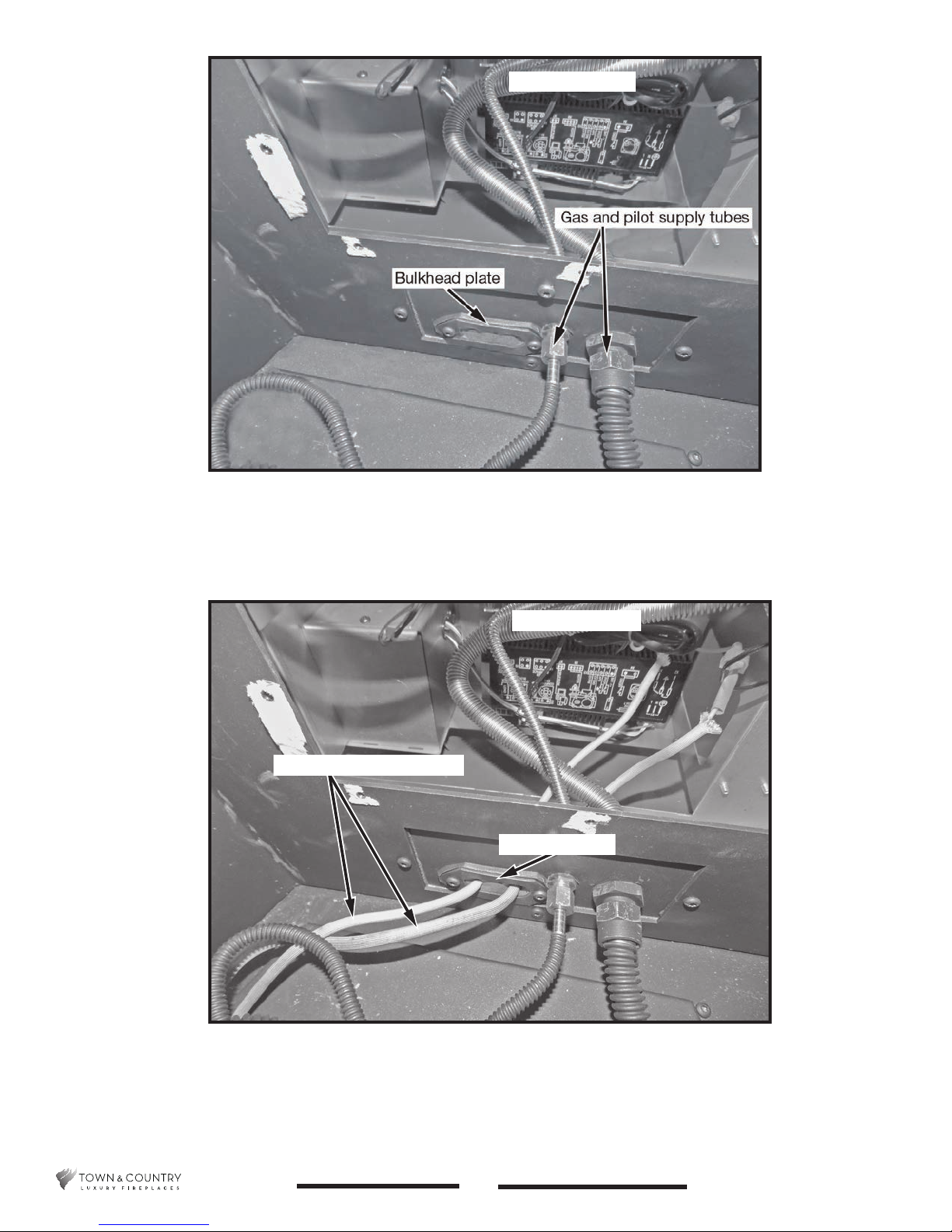
Figure 6: Gas and pilot supply tubes.
Interface module
4. Attach the pilot and gas supply tubes to the bulk head tting and tighten (Figure 6). Ensure the
connections are gas tight.
Interface module
Ignition and sensor wires
Bulkhead plate
Figure 7: Ignition and sensor wires routing.
5. Feed the ignition and sensor wires through the bulkhead plate to the interface module. Tuck the
ignition and sensor wires below the supply tubes (Figure 7).
5056.42702D
4
TC36_NG02DN 020317-16
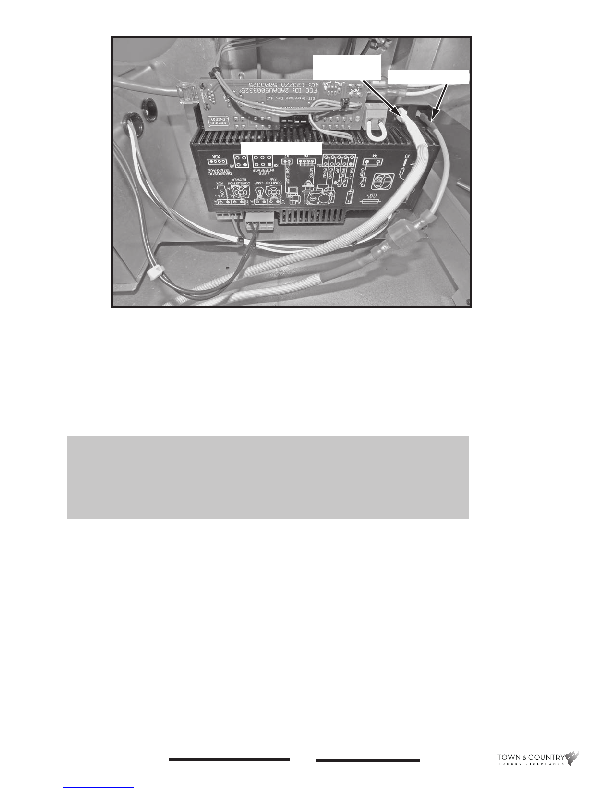
Flame sensor
wire (white)
Interface module
Figure 8: Interface module.
Ignition wire (red)
6. Attach the ignition and sensor wires to the Interface module as shown in Figure 8.
7. Reinstall the valve control center access panel (See Figure 5 on page 3).
A panel set must now be installed before the before the
log grate can be installed. See Installation and Operating
Instructions manual for details.
TC36_NG02DN 020317-16
5
5056.42702D
 Loading...