

Town & Country Fireplaces TC36 Installation And Operating Instructions Manual
IMPORTANT:
THESE INSTRUCTIONS ARE TO
REMAIN WITH THE
HOMEOWNER
FOR YOUR SAFETY
WARNING: If the information in this
manual is not followed exactly, a re or
explosion may result causing property
damage, personal injury or loss of life.
-- Do not store or use gasoline or other
ammable vapours and liquids in the
vicinity of this or any other appliance.
-- WHAT TO DO IF YOU SMELL GAS
• Do not try to light any appliance.
• Do not touch any electrical switch; do
not use any phone in your building.
• Immediately call your gas supplier
from a neighbour’s phone. Follow
the gas supplier’s instructions.
• If you cannot reach your gas supplier,
call the re department.
--Installation and service must be performed
by a quali ed installer, service agency or
the gas supplier.
This appliance may be installed in an
aftermarket permanently located, manufactured home (USA only) or mobile home,
where not prohibited by local codes.
MODEL
TC36
SERIES B
This appliance is only for use with the
type of gas indicated on the rating plate.
This appliance is not convertible for use
with other gases, unless a certi ed kit is
used.
DIRECT VENT FIREPLACE
INSTALLATION
AND OPERATING
INSTRUCTIONS
270904-40 TC36_B 5056.42712

Contents
CAUTION ..............................................................................................................3
SAFETY ................................................................................................................3
INSTALLATION REQUIREMENTS ....................................................................... 5
TOP STANDOFFS ................................................................................................. 5
LOCATING THE FIREPLACE ..............................................................................5
FRAMING AND FINISHING ..................................................................................6
HEARTH EXTENSION .......................................................................................... 8
CONTROL BOX .................................................................................................... 8
CONTROL BOX RELOCATION .......................................................................... 10
VENTING ............................................................................................................. 11
WALL TERMINATION VENTING ........................................................................12
ROOF TERMINATION VENTING .......................................................................16
VENT TERMINAL CLEARANCE ........................................................................ 18
VENT PIPE SEALANT ........................................................................................ 19
INSULATED COLLAR SHIELD .......................................................................... 19
VENT RESTRICTOR ADJUSTMENT ................................................................. 20
MANUFACTURED (MOBILE) HOME ................................................................. 20
GAS SUPPLY ...................................................................................................... 21
OPTIONAL WALL SWITCH ................................................................................ 21
WINDOW FRAME REMOVAL ............................................................................ 22
BRICK PANELS INSTALLATION .......................................................................23
EMBER MATERIAL ............................................................................................ 24
LOG SET ASSEMBLY ........................................................................................ 24
LIGHTING INSTRUCTIONS - Millivolt Valve .................................................... 26
FIRST FIRE .........................................................................................................26
OPERATING .......................................................................................................26
LIGHTING INSTRUCTIONS - Electronic Valve ................................................ 27
FLAME ADJUSTMENT ....................................................................................... 28
MAINTENANCE .................................................................................................. 29
APPENDIX A ....................................................................................................... 29
REPLACEMENT PARTS .............................................................................. 30
REPLACEMENT PARTS-MILLIVOLT CONTROL ASSEMBLY ................... 31
REPLACEMENT PARTS - ELECTRONIC CONTROL ASSEMBLY ............ 32
ELECTRONIC VALVE WIRING DIAGRAM .................................................. 33
WALL TERMINATION KIT ........................................................................... 34
WALL SHIELD/CEILING FIRESTOP THIMBLE .......................................... 34
ROOF TERMINATION KIT ........................................................................... 35
VENT PIPE DIMENSIONS ............................................................................ 36
VENT OFFSET CHART ................................................................................ 37
VARIOUS GAS SUPPLY CONNECTIONS ................................................... 38
SAFETY LABEL LOCATION ........................................................................ 39
2 TC36_B 270904-40
CAUTION
SAFETY
FOR YOUR SAFETY - Do not install or operate your Town
and Country replace without rst reading and understanding
this manual. Any installation or operational deviation from the
following instructions voids the Town and Country FireplacesTM
Warranty and may prove hazardous.
This appliance and its individual shutoff valve must be disconnected from gas supply piping system during any pressure
testing of that system at test pressures in excess of 1/2 psig
(3.5 kPa).
This appliance must be isolated from the gas supply piping
system by closing its individual manual shutoff valve during
any pressure testing of the gas supply piping system at test
pressures equal to or less than 1/2 psig (3.5 kPa).
Note: When lit for the rst time, the appliance will emit a slight
odour for a couple of hours. This is due to the curing of paints,
sealants and lubricants used in the manufacturing process. This
condition is temporary. Open doors and windows to ventilate
area. Smoke and fumes caused by the curing process may
cause discomfort to some individuals.
Do not use the replace if any part has been under water.
Immediately call a quali ed service technician to inspect the
replace and to replace any part of the control system and
any gas control which has been under water.
Due to high temperatures, this gas appliance should
be located out of traf c and away from furniture and
draperies.
Children and adults should be alerted to the hazards of
high surface temperatures and should stay away to avoid
burns or clothing ignition.
Young children should be carefully supervised when they
are in the same room as the appliance.
Clothing or other ammable material should not be placed
on or near the appliance.
Any grill, panel or door removed for servicing the unit
must be replaced prior to operating. Failure to do so
may create a hazardous condition.
Installation and repair should be done by a quali ed service
person. The appliance should be inspected before use
and at least annually by a professional service person.
More frequent cleaning may be required due to excessive
lint from carpeting, bedding material, etc. It is imperative
that control compartments, burners and circulating air
passageways of the appliance be kept clean.
It is our policy that no responsibility is assumed by the
Company or by any of its employees or representatives
for any damages caused by an inoperable, inadequate,
or unsafe condition which is the result, either directly
or indirectly, of any improper operation or installation
procedures.
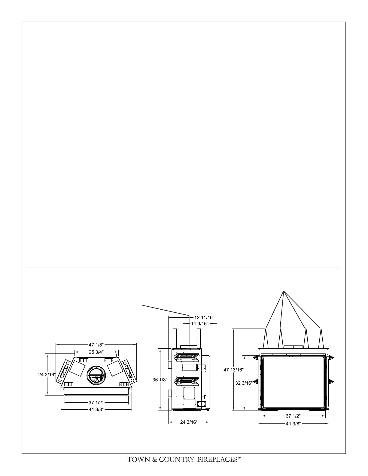
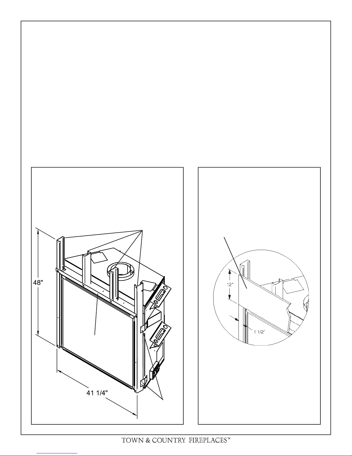
Fig # 1
FIREPLACE DIMENSIONS
CENTER OF
FLUE OUTLET
TOP
STANDOFFS
270904-40 TC36_B 3
COMBUSTIBLE FRAMING
AND FINISH WALL ABOVE
STANDOFFS
MAY USE COMBUSTIBLE
FACING MATERIAL IN THIS
AREA
NONCOMBUSTIBLE FINISH
MATERIAL
SEE FIG #7
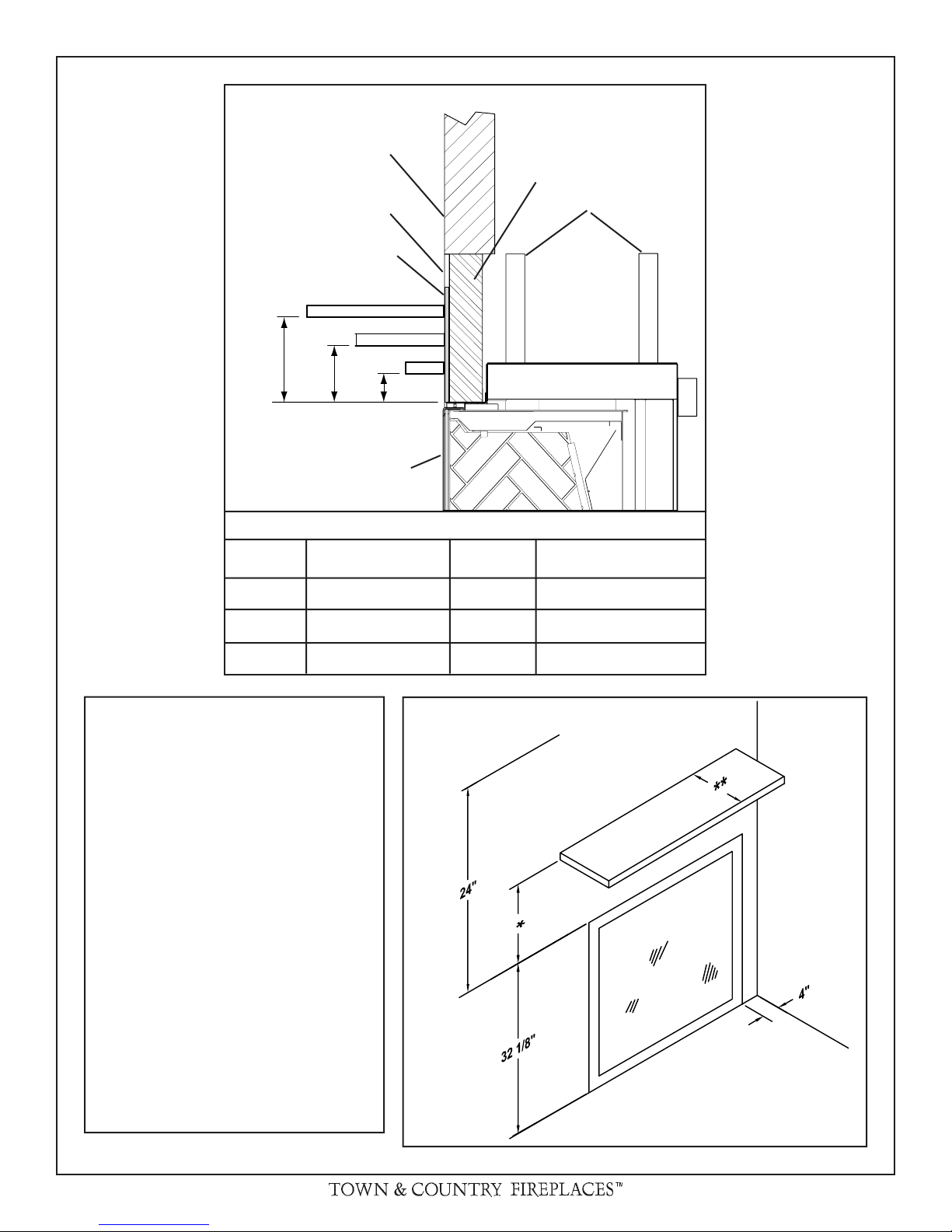
D
Fig. # 2
STEEL FRAMING
STANDOFFS
E
A
B
TOP OF LINTEL BAR
FIREPLACE FRONT
MANTEL CLEARANCE CHART
REF.
A 9" D 12"
B 6" E 6 3/4"
C 3" F 1 1/2"
Minimum Clearances to Combustibles:
Side standoffs ...................... 0 in. (0 mm)
Back standoffs ..................... 0 in. (0 mm)
Top standoffs ....................... 0 in. (0 mm)
Bottom of appliance ............. 0 in. (0 mm)
Adjacent sidewall ................. 4 in. (102 mm)
Ceiling to appliance ........... 24 in. (610 mm)
*Mantel to appliance ..........See Figure #2
**Maximum
Mantel extension ..........See Figure #2
Mantel support ..................... 4 in. (102 mm)
Vertical vent pipe ........... 1-3/4 in. (45 mm)
Horizontal vent pipe
Top ...........................1-3/4 in. (45 mm)
Sides ........................ 1-3/4 in. (45 mm)
Bottom ...................... 1-3/4 in. (45 mm)
MANTEL
*
CLEARANCE
C
F
Fig. # 3
REF.
CEILING
**
MANTEL
DEPTH
MANTEL
UNIT MAY BE RECESSED UP TO
6" WITH NON-COMBUSTIBLE
MASONRY TYPE MATERIAL
ADJACENT
WALL OR
MANTEL
SUPPORT
4 TC36_B 270904-40
INSTALLATION REQUIREMENTS
TOP STANDOFFS
The Town & Country Fireplace installation and venting
must conform to the current CAN/CGA-B149 installation
code (in Canada) or the current National Fuel Gas Code,
ANSI Z223.1 (in the USA), and approved per local codes.
Only quali ed (licensed or trained) personnel should
install this product.
In the state of Massachusetts, only a licensed Plumber
and Gas Fitter may install this product.
Fig. # 4
TOP
STANDOFFS
The top standoffs are shipped loose inside the replace and
must be installed on top of the replace as shown in g. #4.
Do this once the replace is on site and in position.
LOCATING THE FIREPLACE
In planning the installation for the replace, it is necessary to
determine where the unit is to be installed, location of vent
system and where gas supply piping may be plumbed. Various installations are possible, such as, into an existing wall,
a corner, a built-in wall or a wall projection (see Fig. #5). Due
to high temperatures, do not locate this replace in areas of
high traf c or near furniture or draperies.
The minimum clearances from the replace to combustible
surfaces are shown on Fig. # 2 and 3.
Fig. # 5
Examples of Common Locations
CAUTION: When selecting a location, ensure
that there is adequate room on the right hand
or left hand side of the replace for the control
box.
270904-40 TC36_B 5
FRAMING AND FINISHING
Note: The replace must be in place and venting installed
before framing in or building an enclosure around the
unit.
The Town & Country Fireplace may be framed in with building materials (wood and steel studs) or totally enclosed with
non-combustible material, such as facing brick.
Determine the total thickness of facing material to be used.
A total thickness of 3/4" will allow the nishing surface to be
ush with the front of the unit. If preferred, additional masonry
type non-combustible material can be installed above and to
the sides up to 6 inches proud of the appliance.
Once the replace is in its nal position, frame metal studs to
the insides of the framing brackets on each side of the unit.
Ensure that the studs are set back far enough to allow for
thickness of nishing surface. Secure replace to steel studs
with screws. Frame in a steel header directly above the lintel
bar. Additional steel support studs can be added above the
header up to the ceiling.
The sides, back and top of the replace can be framed in
up to the standoffs using conventional 2 x 4 lumber. Heavier
construction may be required for some installations, consult
local building codes for speci c requirements.
Due to high temperatures, concrete board (or other noncombustible material) must be used to sheet in the front of
the replace, extending 12" above and 1 1/2" to the side of
the framing edge bars. See gure #8. Standard sheetrock
(drywall) may be used beyond this.
Chase Insulation: When installing this replace against a
non-insulated exterior wall or chase, it is recommended that
the outer walls be insulated to same degree as other exterior
walls. Do not place replace directly against the insulation.
Cover the insulation and plastic vapour barrier with a solid
surface, such as drywall (sheetrock). Consult local codes.
Fig. # 6
MINIMUM
STEEL STUD FRAMING
DETAIL
STEEL
STUDS
STEEL
HEADER
Fig. # 7
CONCRETE
BOARD
MINIMUM
CONCRETE BOARD
DETAIL
ALL OTHER FRAMING
CAN BE DONE WITH
CONVENTIONAL 2X4
LUMBER
6 TC36_B 270904-40
FRAMING
BRACKETS
Concrete board (or other non-combustible material) must extend 12" above
and 1 1/2" to the sides of the framing
edges.
OPTIONAL STEEL STUD FRAM-
Fig. # 8
ING KIT DIMENSIONS
(TC36.BFRKITA)
Fig. # 9
NON-COMBUSTIBLE RECESSED
INSTALLATION DETAIL
Fig. # 10
48"
Including Sheetrock
NON-COMBUSTIBLE
MASONRY TYPE
MATERIAL
CONCRETE
BOARD
STEEL
STUDS
6"
MINIMUM COMBUSTIBLE FRAMING DIMENSIONS
23 3/8"
54 1/2"
27 3/8"
19 3/8"
*
54 1/2"
11 1/8"
3/4"
48 1/4"
CAUTION:
When framing
for the replace,
ensure adequate
space is provided
*
3/4"
for the control box.
Do not install the
control box above
the replace.
* 48" if framed using the Optional
Steel Stud Framing Kit ( g. #8)
41 1/2" if the replace is framed in
*
place to the minimum steel stud
requirements ( g. #7)
WARNING: Framing dimensions will vary with location of
replace, which may need to be adjusted to accommodate
control box placement and vent installation. Fireplace should
be in it's nal location before framing.
270904-40 TC36_B 7
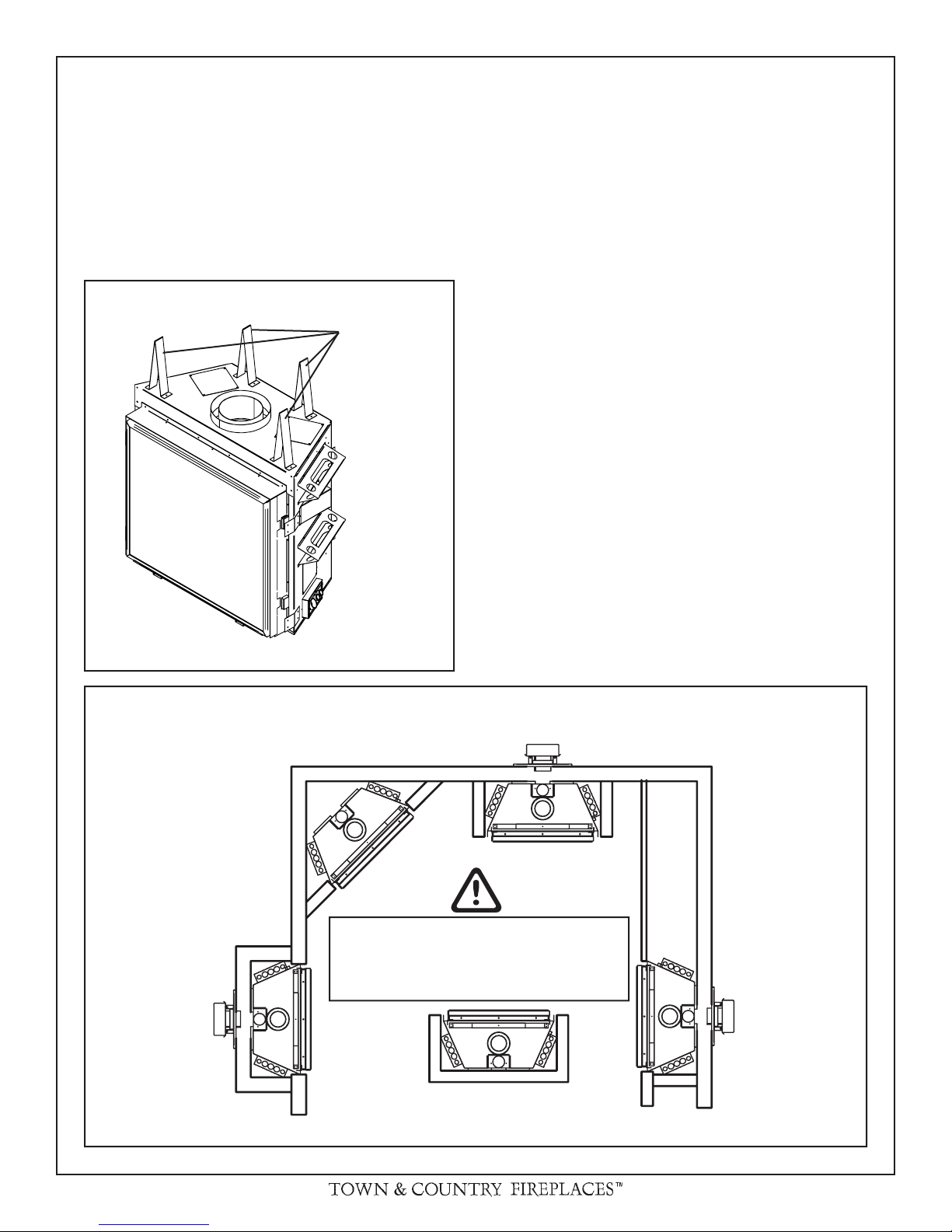
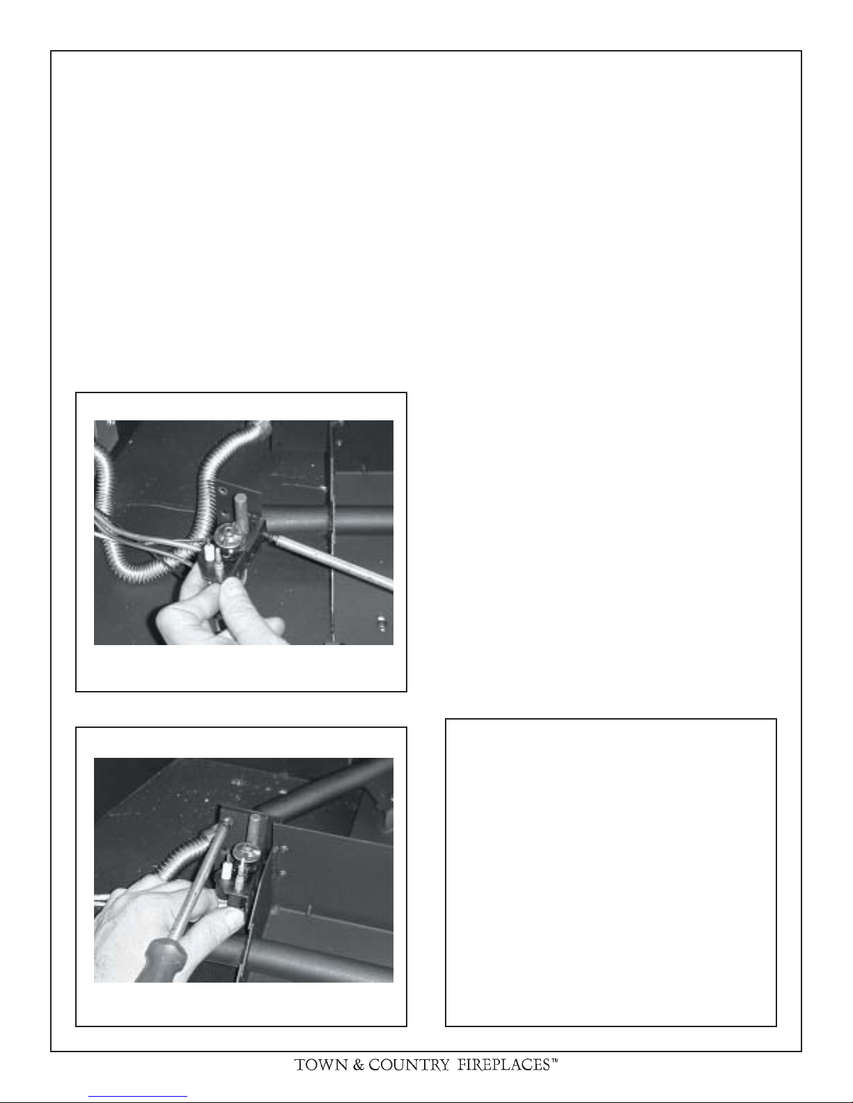
CONTROL BOX
The gas control system is housed in a control box remote of
the replace. Flexible conduits attach the control box to the
replace and house all the plumbing and wiring to the burner.
This unique design allows the control box to be mounted in
a variety of positions on the right or left side of the replace.
The box can be framed into the front right or left face or the
right or left sidewall of the replace enclosure. As the control
system is attached at the factory to exit the right side of the
replace, please see "Control Box Relocation" section to move
the control box to exit the left side.
Caution: When positioning the control box, do not over
bend the conduit or use excessive force, as damage may
occur.
1) Remove window frame latch tool and set aside.
2) Remove 4 screws holding control panel in place and
carefully lift off over the control knobs, being sure not to
damage wires and connections to the "Pilot Flame" indicator (millivolt control system only). Carefully disconnect
wires from indicator, and set aside.
3) Attach control box to framing at predetermined depth,
allowing room for wall nishing material. Side brackets
can be adjusted for a trim t.
4) Attach control box to framing at predetermined depth,
allowing room for wall nishing material. Side brackets
can be adjusted for a trim t.
6) Replace door/inner frame assembly and fasten in place.
Fig. # 11
PILOT
FLAME
INDICATOR
BURNER
SWITCH
MANUAL MILLIVOLT VALVE
CONTROL
BATTERY SPARK
IGNITER
CONDUIT
DOOR AND
FRAME
GAS
VALVE
Note: Gas supply plumbing must be completed and the
spark igniter battery or backup batteries installed before
reinstalling the front control panel.
Fig. # 12
WINDOW
FRAME
1"
MAX
1/4"
HEARTH
EXTENSION
WINDOW
TRACK
FLOOR
SUB-
6) Reconnect "Pilot Flame" indicator wiring and reinstall
control panel.
HEARTH EXTENSION
While a hearth extension is not required
for this replace, one is recommended
for aesthetic reasons. The hearth
extension should be noncombustible
and must not be any more than 1"
above the bottom of the replace. If
thicker, replace must be raised up
accordingly.
Caution: Hearth extensions thicker
than 1" will interfere with the window
frame.
8 TC36_B 270904-40
Fig. # 13
CONTROL BOX LOCATION AND
FRAMING DETAIL
4 1/4"
9 3/8"
Caution: When positioning the control box,
do not over bend the
conduit or use excessive force, as damage
may occur.
12"
CAUTION:
- A 2 foot service access clearance is recommended in front of the control box.
- If recessed into a masonry wall, allow for
control door and frame removal.
- If ush mounted on a masonry wall, allow for
conduit to exit out the bottom of control box.
POSSIBLE CONTROL BOX
LOCATIONS LEFT OR RIGHT
OF THE FIREPLACE
Alternately, the
control may be repositioned from
the right side of
the fireplace to
the left side.
270904-40 TC36_B 9
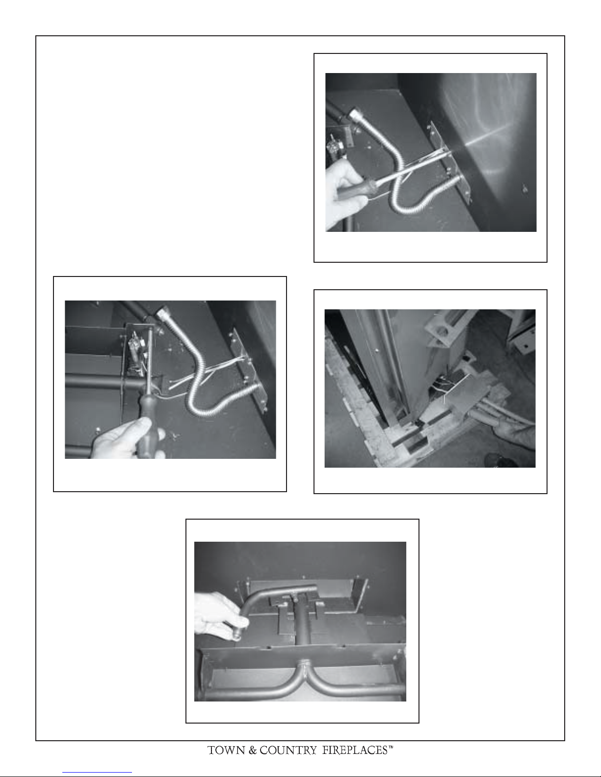
CONTROL BOX RELOCATION
1) Remove glass, logs; grate assembly and rebox panels
if installed.
2) Disconnect ex gas line from the manifold assembly.
3) Remove 2 screws holding pilot bracket to burner pan.
4) Remove 2 screws holding pilot assembly to pilot
bracket.
5) Remove 4 screws holding inlet box to rebox.
6) Pull pilot assembly and plumbing through rebox side,
taking care not to damage pilot, plumbing or wires.
Fig. # 14
Fig. # 15
REMOVE SCREWS HOLDING INLET BOX
Fig. # 16
REMOVE PILOT BRACKET
FROM BURNER ASSEMBLY
Fig. # 17
REPOSITION MANIFOLD
PULL OUT CONTROL ASSEMBLY
10 TC36_B 270904-40
7) Remove casing inlet cover and rebox inlet cover. (Retain
gaskets and screws for reuse). Reinstall both covers on
the opposite side of the unit.
8) Reinstall control assembly into opposite side of unit.
9) Reinstall pilot assembly onto bracket using 2 holes nearest
the bend.
VENTING
Before installing venting for this unit, the installer should read
these instructions to insure that the proper vent con guration
has been selected.
Use only Town and Country Termination kits #:
TCVT.WTA - Wall Termination Kit
TCVT.RTA - Roof Termination Kit
10) Reinstall pilot bracket onto burner pan using the 2 top
most holes.
11) Remove 2 screws holding manifold assembly and reposition it to the opposite side.
12) Reconnect ex gas line ensuring a tight connection.
13) Complete installation of related parts and unit.
Fig. # 18
Vent system components approved for use with the Town and
Country Fireplace are shown in Figure #20.
Various combinations of vertical and horizontal runs may be
used. Refer to #
24 and 25 for details. For optimum performance
and ame appearance, keep the vent length to a minimum and
limit the number of elbows. Connections between each vent
system component must be tightly joined, secured with sheet
metal screws and sealed. A horizontal run of vent should have
a 1/4" rise for every 1 ft. of run towards the termination.
CAUTION: UNDER NO CONDITION SHOULD COMBUSTIBLE MATERIAL BE CLOSER THAN 1 3/4 INCHES FROM
THE TOP AND 1 3/4 INCHES FROM THE SIDES OF A
HORIZONTAL SECTION AND 1 3/4 INCHES FROM THE
VERTICAL SECTIONS OF THE VENT PIPE.
Fig. # 19
REATTACH PILOT BRACKET TO
PILOT ASSEMBLY
REATTACH PILOT BRACKET TO
BURNER ASSEMBLY
Fig. # 20
Vent System Town &
Components Country
12" Pipe Length ........................... TCVT.811X12
18" Pipe Length ........................... TCVT.811X18
24" Pipe Length ........................... TCVT.811X24
48" Pipe Length ........................... TCVT.811X48
18" Adjustable Pipe Length ......... TCVT.811X12ADJ
45° Elbow .................................... TCVT.811XLB45
90° Elbow .................................... TCVT.811XLB90
Wall/Offset Support ..................... TCVT.811XOS
Wall Termination Kit .................... TCVT.WTA
Roof Termination Kit .................... TCVT.RTA
Wall Shield/Ceiling Firestop ......... TCVT.THIMA
Roof Flashing .............................. Any that ts 11" pipe
270904-40 TC36_B 11
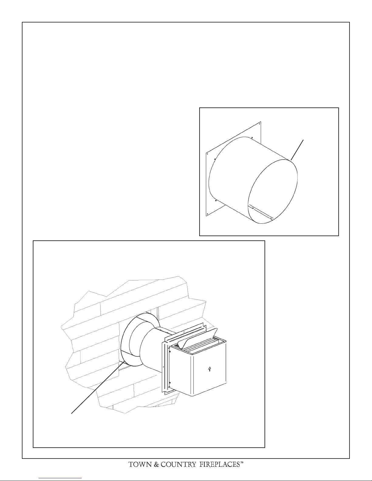
WALL TERMINATION VENTING
Wall thimble:
Exterior wall opening:
Determine the exact position of the replace so that the vent
pipe is centred (if possible) between two building framing
members. Consult your local building codes prior to proceeding. The vent kit will accommodate up to a maximum wall
thickness of 12 inches.
1) Having determined the position of the replace, cut and
frame a 14 1/2 inch opening centred at a minimum height
of
68 1/2 inches above the oor. The opening may be
round or square. Height of the opening will vary with each
installation. As the horizontal vent run increases, so does
the minimum vertical rise (see Fig. #24).
IMPORTANT: When locating the opening, it should be
noted that vent terminal clearances must be maintained.
See "Vent Terminal Clearances" section for proper clearances.
A minimum 2 foot length of pipe is required for any wall termination. With this minimum vertical rise in combination with a
90° elbow, a maximum horizontal run of 18 inches is permitted
(see Fig. #24 and 25). For longer horizontal runs greater than
18 inches, increase vertical rise appropriately.
The rise and run must be constrained to the boundaries of the
chart shown in gure #24. The horizontal run of vent must have
a 1/4" rise for every 1 ft. of run towards the termination.
Where a vent pipe passes through a combustible wall, a wall
thimble/shield must be used to retain insulation and maintain
proper clearances. The wall thimble may be cut to length for
various wall thicknesses up to 12" thick.
Measure the wall thickness including the siding. Trim the
shield to match the wall thickness. Position the wall thimble
from inside through the 14-1/2" opening. Properly adjusted,
the thimble should be ush with the outer wall surface.
Fig. # 22
TRIM TO LENGTH
Fig. # 21
WALL THIMBLE AND VENT
MUST NOT PROTRUDE
BEYOND SIDING
12 TC36_B 270904-40
 Loading...