

Town & Country Fireplaces TC30 SERIES C, TC30 Installation And Operating Instructions Manual
IMPORTANT:
THESE INSTRUCTIONS ARE TO REMAIN
WITH THE HOMEOWNER
FOR YOUR SAFETY
WARNING: If the information in this manual
is not followed exactly, a re or explosion
may result causing property damage,
personal injury or loss of life.
-- Do not store or use gasoline or other
ammable vapors and liquids in the vicinity
of this or any other appliance.
TC30
-- WHAT TO DO IF YOU SMELL GAS
• Do not try to light any appliance.
• Do not touch any electrical switch; do
not use any phone in your building.
• Immediately call your gas supplier
from a neighbour’s phone. Follow
the gas supplier’s instructions.
• If you cannot reach your gas supplier,
call the re department.
-- Installation and service must be
performed by a quali ed installer, service
agency or the gas supplier.
This appliance may be installed in an aftermarket permanently located, manufactured
home (USA only) or mobile home, where
not prohibited by local codes.
INSTALLATION
AND OPERATING
INSTRUCTIONS
This appliance is only for use with the
type of gas indicated on the rating plate.
This appliance is not convertible for use
with other gases, unless a certi ed kit is
used.
220906-40 TC30.CE 5056.429
MODEL TC30
SERIES C
MODULAR DIRECT VENT
FIREPLACE

Contents
CAUTION .............................................................................................................. 3
SAFETY .................................................................................................................3
MASSACHUSETTS RULES AND REGULATIONS ............................................... 4
INSTALLATION REQUIREMENTS ........................................................................ 5
LOCATING THE FIREPLACE ............................................................................... 5
TOP STANDOFFS .................................................................................................5
MANTEL CLEARANCES ....................................................................................... 6
FRAMING AND FINISHING ..................................................................................7
MAESTRO CONTROL SYSTEM ........................................................................... 9
HEARTH EXTENSION ........................................................................................ 18
VENTING ............................................................................................................. 18
WALL TERMINATION VENTING ......................................................................... 18
ROOF TERMINATION VENTING ........................................................................ 23
VENT TERMINAL CLEARANCE ......................................................................... 25
VENT PIPE SEALANT ......................................................................................... 26
VENT RESTRICTOR ADJUSTMENT ..................................................................27
MANUFACTURED (MOBILE) HOME .................................................................. 27
GAS SUPPLY ...................................................................................................... 28
WINDOW FRAME REMOVAL ............................................................................. 28
FIREBOX PANELS INSTALLATION ....................................................................29
FIRST FIRE ......................................................................................................... 30
LIGHTING INSTRUCTIONS ............................................................................... 30
APPENDIX A .......................................................................................................31
MAINTENANCE .................................................................................................. 31
REPLACEMENT PARTS .............................................................................. 32
REPLACEMENT PARTS - MAESTRO CONCEALED VALVE ...................... 33
POWER VENT WIRING DIAGRAM .............................................................. 34
WALL TERMINATION KIT ............................................................................. 35
WALL SHIELD/CEILING FIRESTOP THIMBLE ............................................ 35
ROOF TERMINATION KIT ............................................................................ 35
VENT PIPE DIMENSIONS ............................................................................ 36
VENT OFFSET CHART ................................................................................37
STEEL STUD FRAMING KIT ........................................................................ 38
SAFETY LABEL LOCATION ......................................................................... 39
2 TC30.CE 220906-40
CAUTION
SAFETY
FOR YOUR SAFETY - Do not install or operate your Town
& Country fi replace without fi rst reading and understanding
this manual. Any installation or operational deviation from the
following instructions voids the Town & Country Fireplaces
TM
Warranty and may prove hazardous.
This appliance and its individual shutoff valve must be disconnected from gas supply piping system during any pressure
testing of that system at test pressures in excess of 1/2 psig
(3.5 kPa).
This appliance must be isolated from the gas supply piping
system by closing its individual manual shutoff valve during
any pressure testing of the gas supply piping system at test
pressures equal to or less than 1/2 psig (3.5 kPa).
Note: When lit for the fi rst time, the appliance will emit a slight
odour for a couple of hours. This is due to the curing of paints,
sealants and lubricants used in the manufacturing process. This
condition is temporary. Open doors and windows to ventilate
area. Smoke and fumes caused by the curing process may
cause discomfort to some individuals.
Do not use the fi replace if any part has been under water.
Immediately call a qualifi ed service technician to inspect the
fi replace and to replace any part of the control system and
any gas control which has been under water.
For gas-fueled products we recommend that our gas hearth
products be installed and serviced by professionals who
are certifi ed in the United States by NFI (National Fireplace
Institute).
Due to high temperatures, this gas appliance should
be located out of traffi c and away from furniture and
draperies.
Children and adults should be alerted to the hazards of
high surface temperatures and should stay away to avoid
burns or clothing ignition.
Young children should be carefully supervised when they
are in the same room as the appliance.
Clothing or other fl ammable material should not be placed
on or near the appliance.
Any grill, panel or door removed for servicing the unit
must be replaced prior to operating. Failure to do so
may create a hazardous condition.
Installation and repair should be done by a qualifi ed service
person. The appliance should be inspected before use
and at least annually by a professional service person.
More frequent cleaning may be required due to excessive
lint from carpeting, bedding material, etc. It is imperative
that control compartments, burners and circulating air
passageways of the appliance be kept clean.
It is our policy that no responsibility is assumed by the
Company or by any of its employees or representatives
for any damages caused by an inoperable, inadequate,
or unsafe condition which is the result, either directly
or indirectly, of any improper operation or installation
procedures.
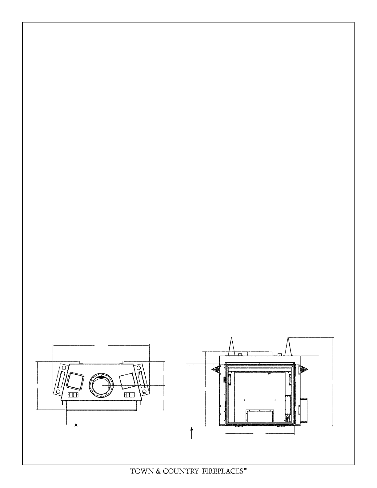
Fig # 1
21 3/4
FIREPLACE DIMENSIONS
43 1/2
31 1/2
LINTEL WIDTH LINTEL HEIGHT
10 3/4
11 9/16
This appliance must not be connected to a chimney fl ue
serving a separate solid fuel burning appliance.
34 1/16
28 3/16
31 1/2
40 1/4
32
220906-40 TC30.CE 3

Important Note for the Commonwealth of Massachusetts:
From Massachusetts Rules and Regulations 248 CMR 5.08:
(a) For all side wall horizontally vented gas fuelled equipment installed in every dwelling, building or structure used in whole or in
part for residential purposes, including those owned or operated by the Commonwealth and where the side wall exhaust vent termination
is less than seven (7) feet above fi nished grade in the area of the venting, including but not limited to decks and porches, the following
requirements shall be satisfi ed.
1. INSTALLATION OF CARBON MONOXIDE DETECTORS. At the time of installation of the side wall horizontal vented gas
fuelled equipment, the installing plumber or gasfi tter shall observe that a hard wired carbon monoxide detector with an alarm and battery
back-up is installed on the fl oor level where the gas equipment is to be installed, in addition, the installing plumber or gasfi tter shall observe
that a battery operated or hard-wired carbon monoxide detector with an alarm is installed on each additional level of the dwelling, building
or structure served by the side wall horizontal vented gas fuelled equipment. It shall be the responsibility of the property owner to secure
the services of qualifi ed licensed professionals for the installation of hard-wired carbon monoxide detectors.
a. In the event that the side wall horizontally vented gas fuelled equipment is installed in a crawl space or an attic, the hard-wired
carbon monoxide detector with alarm and battery back-up may be installed on the next adjacent fl oor level.
b. In the event that the requirements of this subdivision cannot be met at the time of completion of installation, the owner shall have
a period of thirty (30) days to comply with the above requirements; provided, however, that during said thirty (30) day period, a battery
operated carbon monoxide detector with an alarm shall be installed.
2. APPROVED CARBON MONOXIDE DETECTORS. Each carbon monoxide detector as required in accordance with the above
provisions shall comply with NFPA 720 and be ANSI/UL 2034 listed as IAS certifi ed.
3. SIGNAGE. A metal or plastic identifi cation plate shall be permanently mounted to the exterior of the building at a minimum
height of eight (8) feet above grade directly in line with the exhaust vent terminal for the horizontally vented gas fuelled heating appliance
or equipment. The sign shall read, in print size no less than one-half (1/2) inch in size, “GAS VENT DIRECTLY BELOW. KEEP CLEAR
OF ALL OBSTRUCTIONS”.
4. INSPECTION. The state or local gas inspector of the side wall horizontally vented gas fuelled equipment shall not approve the
installation unless, upon inspection, the inspector observes carbon monoxide detectors and signage installed in accordance with the provisions of 248 CMR 5.089(2)(a) 1 through 4.
(b) EXEMPTIONS. The following equipment is exempt from 248 CMR 5.089(2)(a) 1 through 4.
1. The equipment listed in Chapter 10 entitled “Equipment Not Required To Be Vented” in the most current edition of NFPA 54 as
adopted by the Board; and
2. Product Approved side wall horizontal vented gas fuelled equipment installed in a room or structure separate from the dwelling,
building or structure used in whole or in part for residential purposes.
(c) MANUFACTURER REQUIREMENTS – GAS EQUIPMENT VENTING SYSTEM PROVIDED. When the manufacturer of
Product Approved side wall horizontally vented gas equipment provides a venting system design or venting system components with the
equipment, the instructions provided by the manufacturer for installation of the equipment and the venting system shall include:
1. Detailed instructions for the installation of the venting system design or the venting system components; and
2. A complete parts list for the venting system design or venting system.
(d) MANUFACTURER REQUIREMENTS – GAS EQUIPMENT VENTING SYSTEM NOT PROVIDED. When the manufacturer
of a Product Approved side wall horizontally vented gas fuelled equipment does not provide the parts for venting the fuel gases, but identifi es “special venting systems”, the following requirements shall be satisfi ed by the manufacturer.
1. The referenced “special venting system” instructions shall be included with the appliance or equipment installation instructions;
and
2. The “special venting systems” shall be Product Approved by the Board, and the instructions for that system shall include a parts
list and detailed installation instructions.
(e) A copy of all installation instructions for all Product Approved side wall horizontally vented gas fuelled equipment, all venting
instructions, all parts lists for venting instructions, and/or all venting design instructions shall remain with the appliance or equipment at the
completion of the installation.
4 TC30.CE 220906-40
INSTALLATION REQUIREMENTS
TOP STANDOFFS
The Town & Country Fireplace installation and venting
must conform to the current CAN/CGA-B149 installation
code (in Canada) or the current National Fuel Gas Code,
ANSI Z223.1 (in the USA), and approved per local codes.
Only qualifi ed (licensed or trained) personnel should
install this product.
In the state of Massachusetts, only a licensed Plumber
and Gas Fitter may install this product.
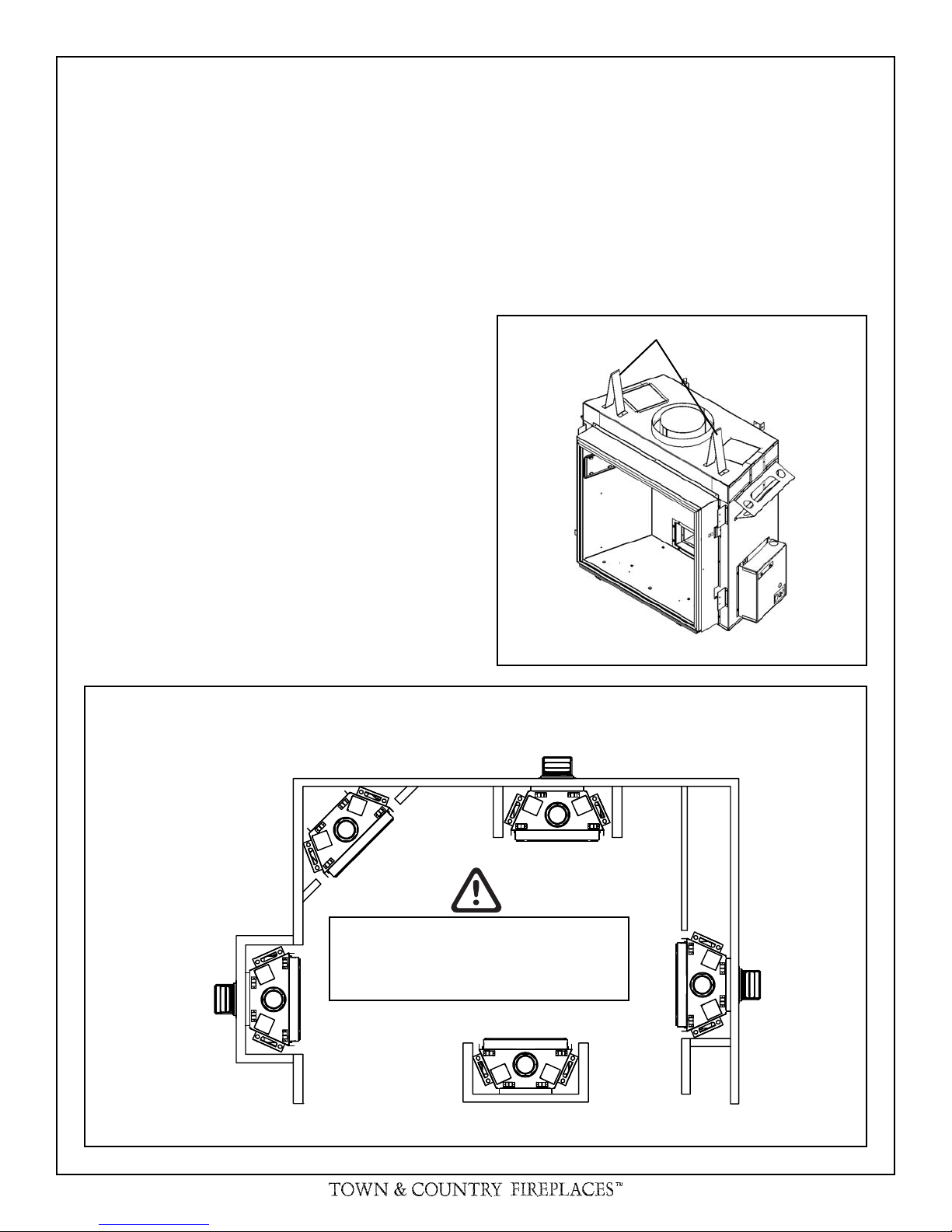
LOCATING THE FIREPLACE
In planning the installation for the fi replace, it is necessary
to determine where the unit is to be installed, location of
vent system and where gas supply piping may be plumbed.
Various installations are possible, such as, into an existing
wall, a corner, a built-in wall or a wall projection (Fig 5). Due
to high temperatures, do not locate this fi replace in areas of
high traffi c or near furniture or draperies.
The minimum clearances from the fi replace to combustible
surfaces must be adhered to and are shown in Fig 2 and
Fig 3.
The top standoffs are shipped loose inside the fi replace and
must be installed on top of the fi replace as shown in Fig 4. Do
this once the fi replace is on site and in position.
Fig. # 4
TOP STANDOFFS
Fig. # 5
SEE FIG #9 FOR
DIMENSIONS
Examples of Common Locations
CAUTION: When selecting a location, ensure
that there is adequate room on the right hand
or left hand side of the fi replace for the control
box.
220906-40 TC30.CE 5
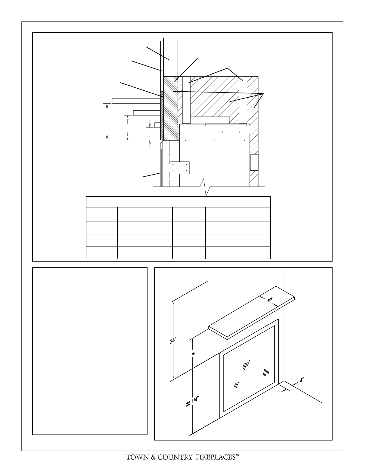
COMBUSTIBLE FRAMING AND
FINISH WALL ABOVE STANDOFFS
MAY USE COMBUSTIBLE FACING
MATERIAL IN THIS AREA
Fig. # 2
STEEL FRAMING
STANDOFFS
NON-COMBUSTIBLE
FINISH MATERIAL
SEE FIG #7
A
TOP OF LINTEL BAR
FIREPLACE FRONT
REF.
A 12" D 12"
B 9" E 6 3/4"
D
E
F
B
C
MANTEL CLEARANCE CHART
MANTEL
*
CLEARANCE
REF.
**
NON-COMBUSTIBLE ZONE.
DO NOT INSTALL ANY
COMBUSTIBLE MATERIAL,
ELECTRICAL WIRING OR
GAS PLUMBING IN THIS
AREA.
MANTEL
DEPTH
C 6" F 1 1/2"
Minimum Clearances to Combustibles:
Side standoffs ...................... 0 in. (0 mm)
Back standoffs ..................... 0 in. (0 mm)
Top standoffs ....................... 0 in. (0 mm)
Bottom of appliance ............. 0 in. (0 mm)
Adjacent sidewall ................. 4 in. (102 mm)
Ceiling to appliance ........... 24 in. (610 mm)
*Mantel to appliance ..........See Figure #2
**Maximum
Mantel extension ..........See Figure #2
Mantel support ..................... 4 in. (102 mm)
Vertical vent pipe ........... 1-3/4 in. (45 mm)
Horizontal vent pipe
Top ............................ 1-3/4 in. (45 mm)
Sides ........................ 1-3/4 in. (45 mm)
Bottom ...................... 1-3/4 in. (45 mm)
Fig. # 3
CEILING
MANTEL
ADJACENT
WALL OR
MANTEL
SUPPORT
UNIT MAY BE RECESSED UP TO
6" WITH NON-COMBUSTIBLE
MASONRY TYPE MATERIAL
6 TC30.CE 180506-40
FRAMING AND FINISHING
Note: The fi replace should be in place and venting in-
stalled before framing in or building an enclosure around
the unit.
The Town & Country fi replace must be framed in as described
below or totally enclosed with non-combustible material, such
as facing brick.
frame to the fi replace once the fi replace is in its fi nal position.
Secure the steel frame to the framing brackets on each side
of the unit. Ensure that the studs are set back far enough to
allow for thickness of fi nishing surface.
The sides, back and top of the fi replace can be framed in
up to the steel studs and the fi replace standoffs using con-
ventional lumber. Consult local building codes for specifi c
requirements.
Determine the total thickness of facing material to be used.
A thickness of 3/4" will allow the fi nishing surface to be fl ush
with the front of the unit. If preferred, additional masonry type
non-combustible material can be installed above and to the
sides up to 6 inches proud of the appliance. The fi nishing
material must not interfere with glass frame access.
A Steel Stud Framing Kit is supplied with the fi replace and
must be used unless the fi replace is totally enclosed with
non-combustible material. Assemble the framing kit as per
the instructions on page 38 of this manual. Attach the steel
Fig. # 6
NONCOMBUSTIBLE
ZONE. DO NOT INSTALL
ANY COMBUSTIBLE
MATERIAL, ELECTRICAL
WIRING, INSULATION,
PLASTIC VAPOUR
BARRIER OR GAS
PLUMBING WITHIN THE
STEEL STUD FRAMING
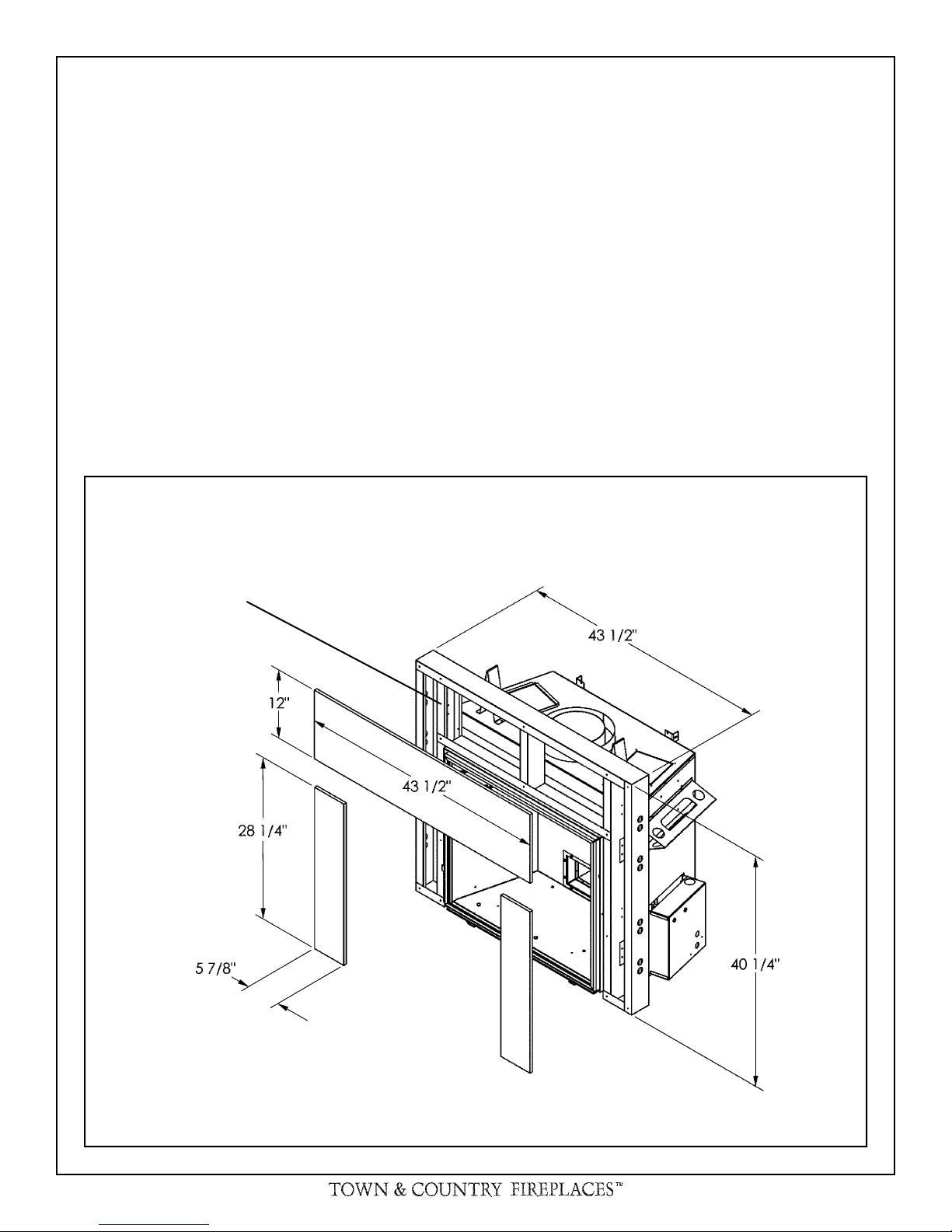
Due to high temperatures, concrete board is supplied with
the fi replace and must be used to sheet in the front of the
fi replace, extending 12" above and 5 7/8" to the side of the
framing edge bars. (Fig 7) Standard sheetrock (drywall) may
be used beyond this.
Chase Insulation: When installing this fi replace against a
non-insulated exterior wall or chase, it is recommended that the
outer walls be insulated to same degree as other exterior walls.
Do not place fi replace directly against the insulation. Cover the
insulation and plastic vapour barrier with a solid surface, such
as drywall (sheetrock). Consult local codes. Do not insulate
or use plastic vapour barrier within the framing kit.
STEEL STUD FRAMING KIT
DIMENSIONS
(Supplied with fi replace)
ALL OTHER FRAMING
CAN BE DONE WITH
CONVENTIONAL
LUMBER
220906-40 TC30.CE 7

Fig. # 7
CONCRETE
BOARD
CONCRETE BOARD
DETAIL
Fig. # 8
NON-COMBUSTIBLE RECESSED
INSTALLATION DETAIL
Concrete board (or other noncombustible material) must extend 12"
above and 5 7/8" to the sides of the
framing edges.
Fig. # 9
NON-COMBUSTIBLE
MASONRY TYPE
MATERIAL
CONCRETE
BOARD
STEEL
STUDS
MINIMUM COMBUSTIBLE FRAMING DIMENSIONS
Including Sheetrock
WARNING: Fireplace should be in its fi nal location before
framing.
8 TC30.CE 220906-40
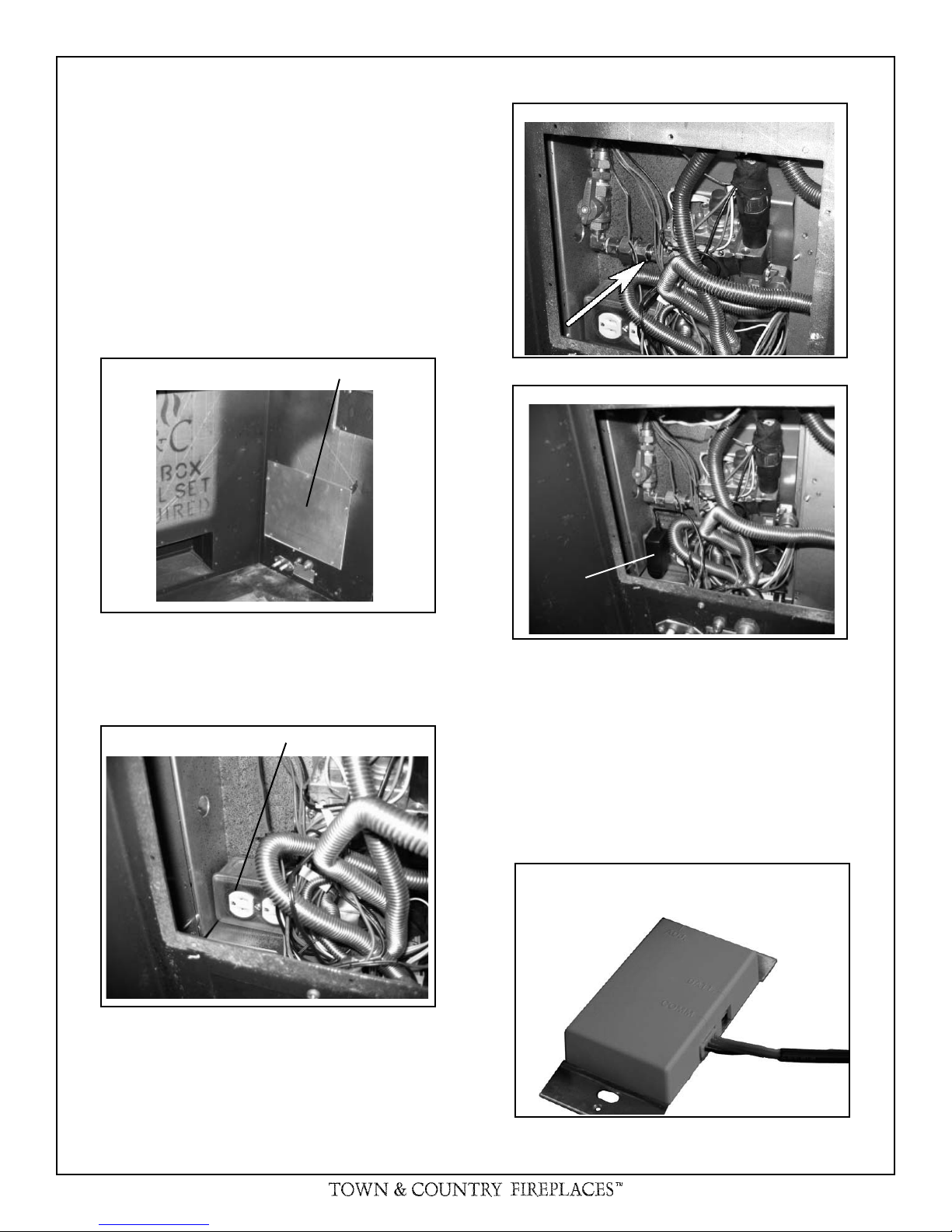
MAESTRO CONTROL SYSTEM
AC ADAPTER
The gas control system is located on the right hand side of
the fi rebox behind an access panel and the decorative brick
panel. The fi replace is operated via a wall switch that can be
located up to 25 ft away from the fi replace and also by a hand
held remote control unit.
Installation
1) Locate the fi replace in the desired location.
2) Remove access panel from right hand side of the fi rebox
(Fig 10)
Fig. # 12
Fig. # 10
ACCESS PANEL
3) Connect a 110v AC electrical supply to the outlet installed
inside the control box (Fig 11)
Fig. # 11
OUTLET
Fig. # 13
AC ADAPTER
7) Route the control cable as required to the wall control
electrical box.
8) Attach the control cable to the wall control. (Fig 14)
9) Insert the 4 supplied “AA” batteries into the battery pack
and connect to wall control. (Fig 15)
10) Fasten the wall switch to the electrical box.
11) Fasten the faceplate to switch
12) Turn on the gas supply and check that all connections are
tight and leak free.
4) Connect the gas supply to the valve (Fig 12)
5) Plug the A/C adaptor into the outlet (Fig 13)
6) Attach the electrical box for the supplied wall control to the
framing in the desired location (up to 25ft away).
220906-40 TC30.CE 9
Fig. # 14
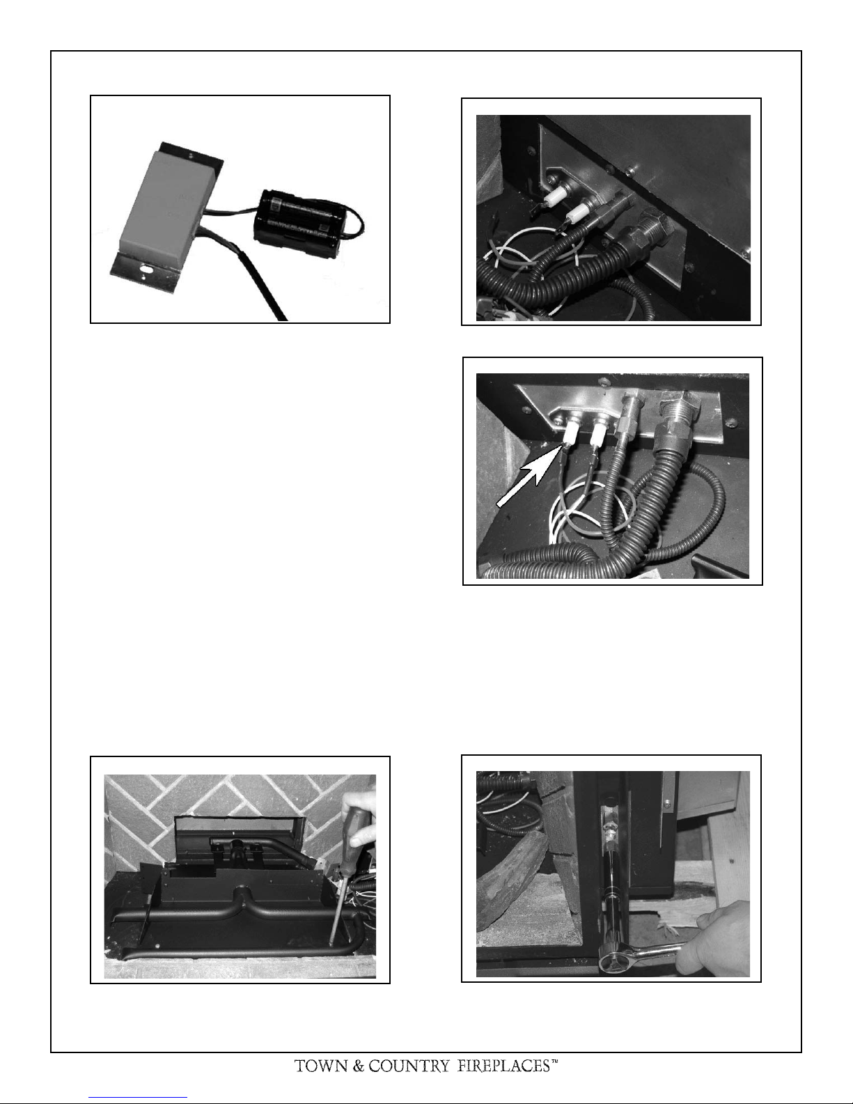
Fig. # 15 Fig. # 17
Burner installation
1) Remove the burner from the packaging and secure it to
the base of the fi replace with the 2 screws provided. (Fig
16)
2) Connect the fl ex hoses from the pilot and the main burner
supply to the bulkhead fi ttings on the fi rebox. (Fig 17)
3) Connect the electrical connections from the pilot assembly
to the connections in the fi rebox side. Ensure that the wire
from the spark electrode is connected to the rear of the
two connectors in the bulkhead. (Fig 18)
Fig. # 18
Note: If you need to test the supply pressure, turn off the gas
supply before removing the blanking plug from the supply
pressure test port.
Fig. # 16
4) Remove the pressure test point pipe plug from the manifold
test port. The plug is located between the right side lintel
and fi rebox side. (Fig 19)
Fig. # 19
10 TC30.CE 220906-40
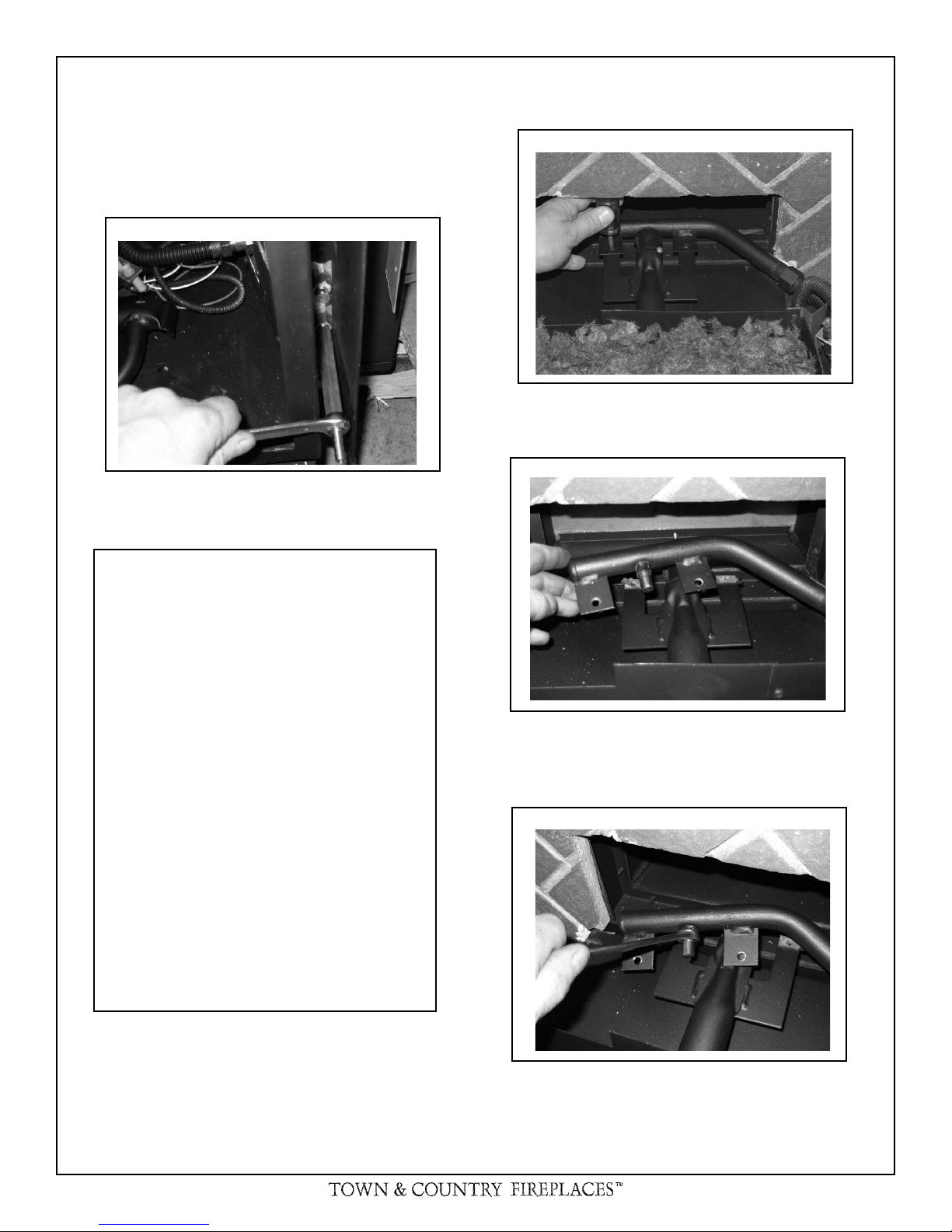
5) Thread the extension piece into the open test port.
(Fig 20)
6) Attach a pressure gauge onto the hose barb on the now
installed extension piece.
If this fi replace is to be used on natural gas go
to step 17.
Fig. # 20
If the unit is to be used on propane convert as
follows using the components supplied with
this fi replace:
7) Remove the two screws securing the manifold assembly
to the burner. (Fig 21)
Fig. # 21
8) Remove the manifold assembly from the burner.
(Fig 22)
Fig. # 22
Warning:
This conversion kit shall be installed
by a qualifi ed service agency in accor-
dance with the manufacturer's instructions and all applicable codes and
requirements of the authority having
jurisdiction. If the information in these
instructions is not followed exactly, a
fi re, explosion or prodcution of carbon
monoxide may result causing property
damage, personal injury or loss of life.
The qualifi ed service agency is respon-
sible for the proper installation of this
kit. The installation is not proper and
complete until the operation of the converted appliance is checked as specifi ed
in the maufacturer's instructions supplied with the kit.
9) With a ½” wrench remove the natural gas orifi ce (#32) and
replace with propane orifi ce (#48)(our part # 5021.3407)
(Fig 23)
Fig. # 23
Caution: The gas supply shall be shut
off prior to disconnecting the electrical power , before proceeding with the
conversion.
220906-40 TC30.CE 11
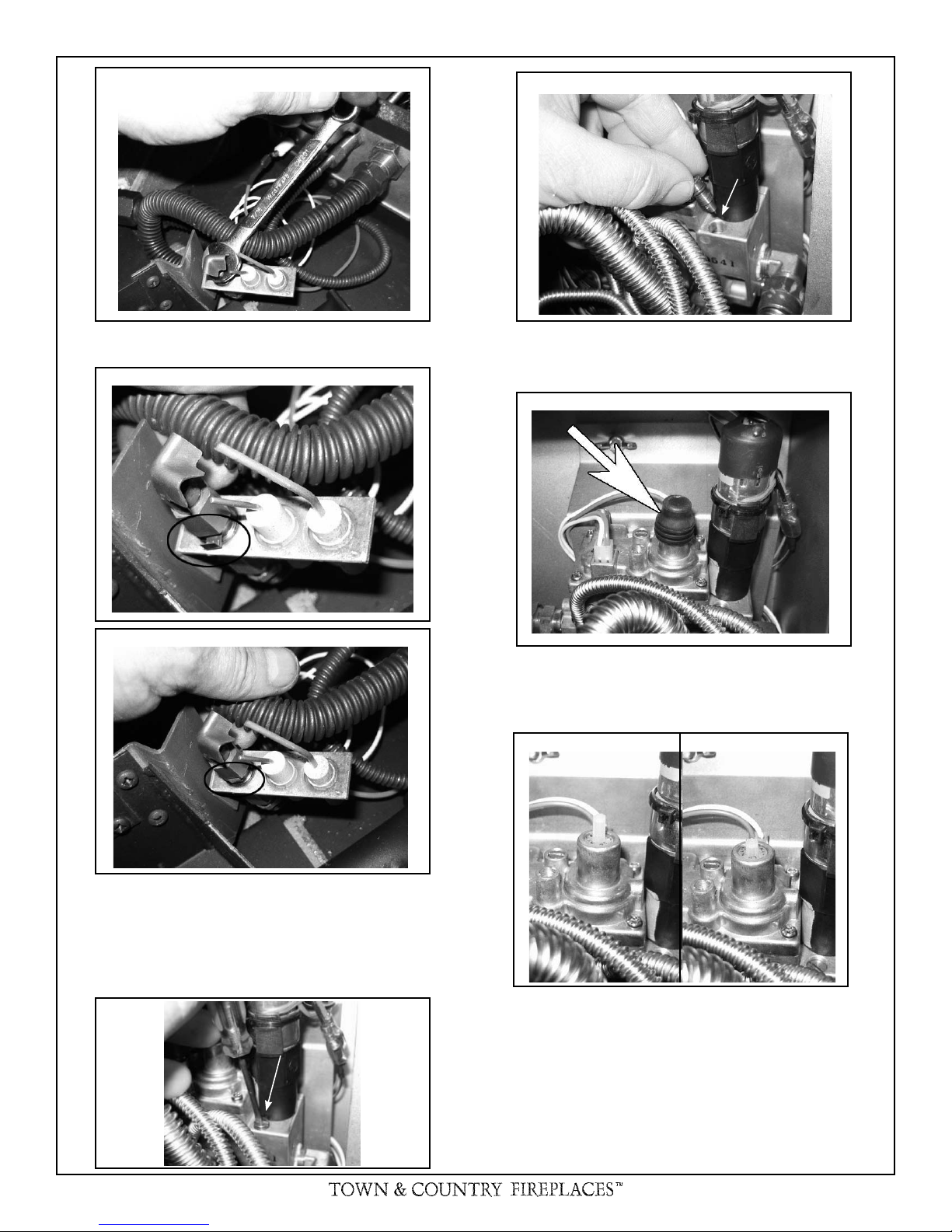
Fig. # 24
Fig. # 28
Minimum
rate screw
10) With a 7/16” wrench loosen the pilot head on the pilot assembly
by a half-turn (Fig 24)
Fig. # 25
Fig. # 26
13) Replace the minimum rate screw with the one provided
in the propane conversion kit supplied with this fi replace.
Ensure that the screw is fully installed. (Fig 28)
Fig. # 29
14) Pull off the rubber cap from the top of the pressure regulator. (Fig 29) The pressure regulator adjustment tube is
now accessible.
Fig. # 30
NG LP
11) Slide the pilot adjustment band over and ensure that the hole
in the orifi ce band is showing. (Fig 25 shows NG position,
Fig 26 shows LP position)
12) Remove the minimum rate screw located in the valve.
(Fig 27)
Fig. # 27
Minimum
rate screw
12 TC30.CE 220906-40
15) Press down on the center tube and rotate 90°. The center tube should stay down. (Fig 30). Replace the rubber
cap.
 Loading...