

Town & Country Fireplaces TC30.NG04D Instructions Manual

INSTALLER: Leave this manual with the appliance.
CONSUMER: Retain this manual for future reference.
These instructions are supplementary to the Installation
and Operating Instructions supplied with the replace
and should be kept together. Refer to the Installation
and Operating Instructions for proper gas supply, safety
requirements and operating instructions.
TC30
TRANQUILITY
BURNER KIT
INSTRUCTIONS
270315-16 TC30_NG04D 5056.42904D
PART#
TC30.NG04D
For TC30 Series D
Fireplaces
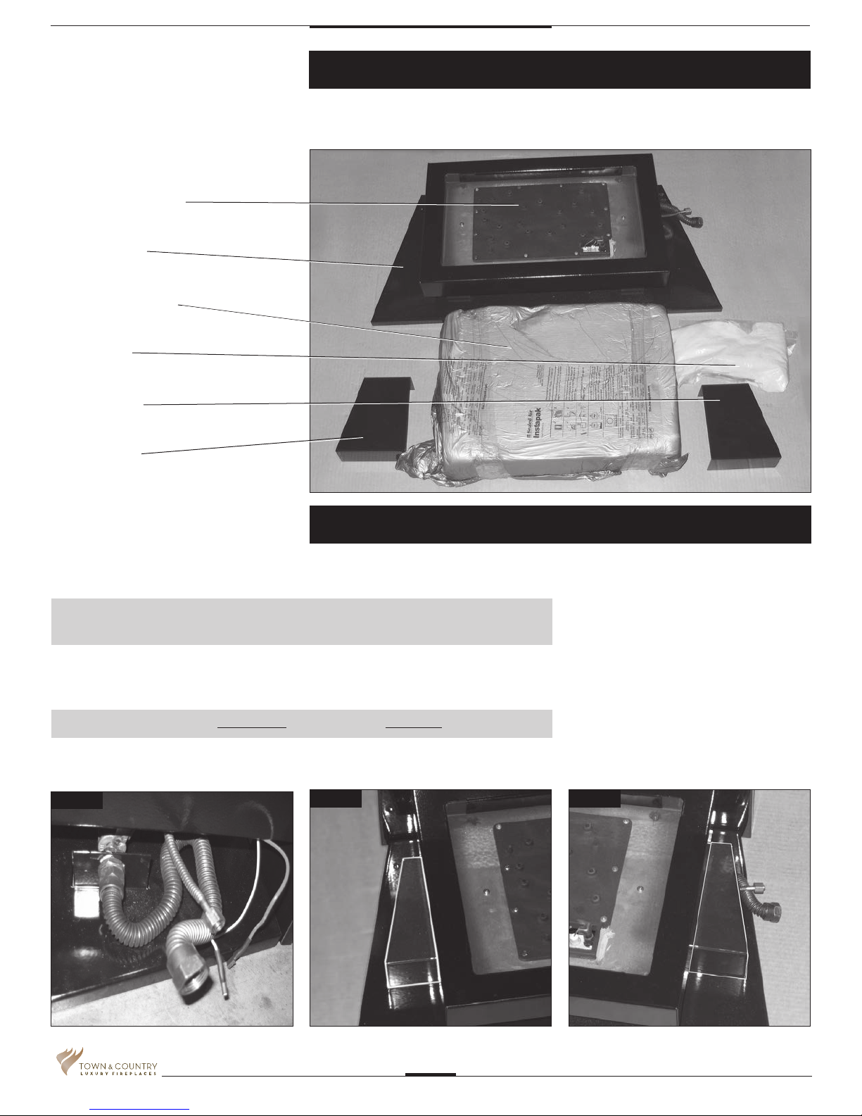
1 BURNER ASSEMBLY
1 PANEL, BASE
1 PEBBLE ASSEMBLY
2.2 LBS. SAND
1 COVER RHS
1 COVER LHS
Contents of Package
1 BAG TAPERED PLUGS (NOT SHOWN)
Tranquility Burner Installation
If converting to propane see conversion instructions on page #6
before proceeding.
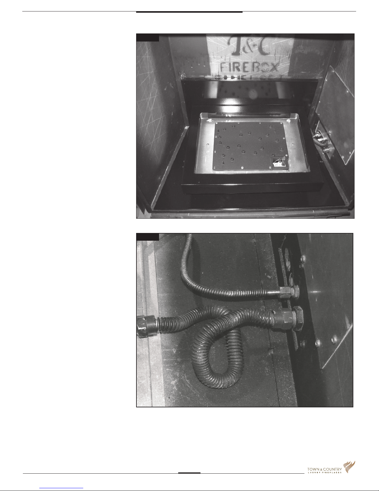
NOTE: Plug the 4 vacant holes in the bottom of the rebox with 1/2” screws,
as they are not required to attach this style of burner.
1. Bend ex lines into the approximate shape. (Fig #1)
2. Place covers under the burner tray. (Fig #2 & 3)
NOTE: Shutter must be fully closed for Natural gas, half open for Propane.
Fig #1
Fig #2
Fig #3
5056.42904D
TC30_ng04D_270315-16
2
3. Position lower rear porcelain panel
centered at the rear of the rebox. Place
burner assembly into the rebox against
the rear panel.
(Fig #4)
4. Attach the manifold supply tube and
the pilot supply tube to the bulk head
ttings and tighten. (Fig. #5) Ensure
that there are no leaks.
Fig #4
Fig #5
TC30_ng04D_270315-16
5056.42904D
3
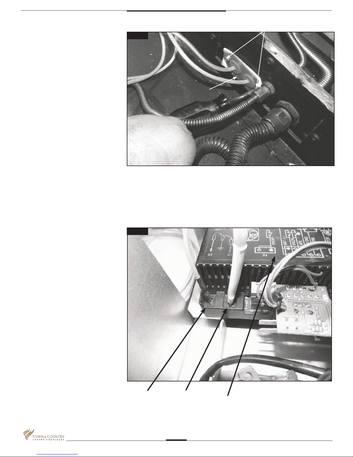
4. Secure the electrical bulkhead plate
(Fig.#6) and gasket to the rebox. (2
screws) Attach the ignition and sensor
wires to the module. (Fig.#7)
2 SCREWS
Fig #6
BULKHEAD PLATE
Fig #7
IGNITION
WIRE
(RED)
FLAME
SENSOR
WIRE
(WHITE)
INTERFACE
MODULE
5056.42904D
TC30_ng04D_270315-16
4
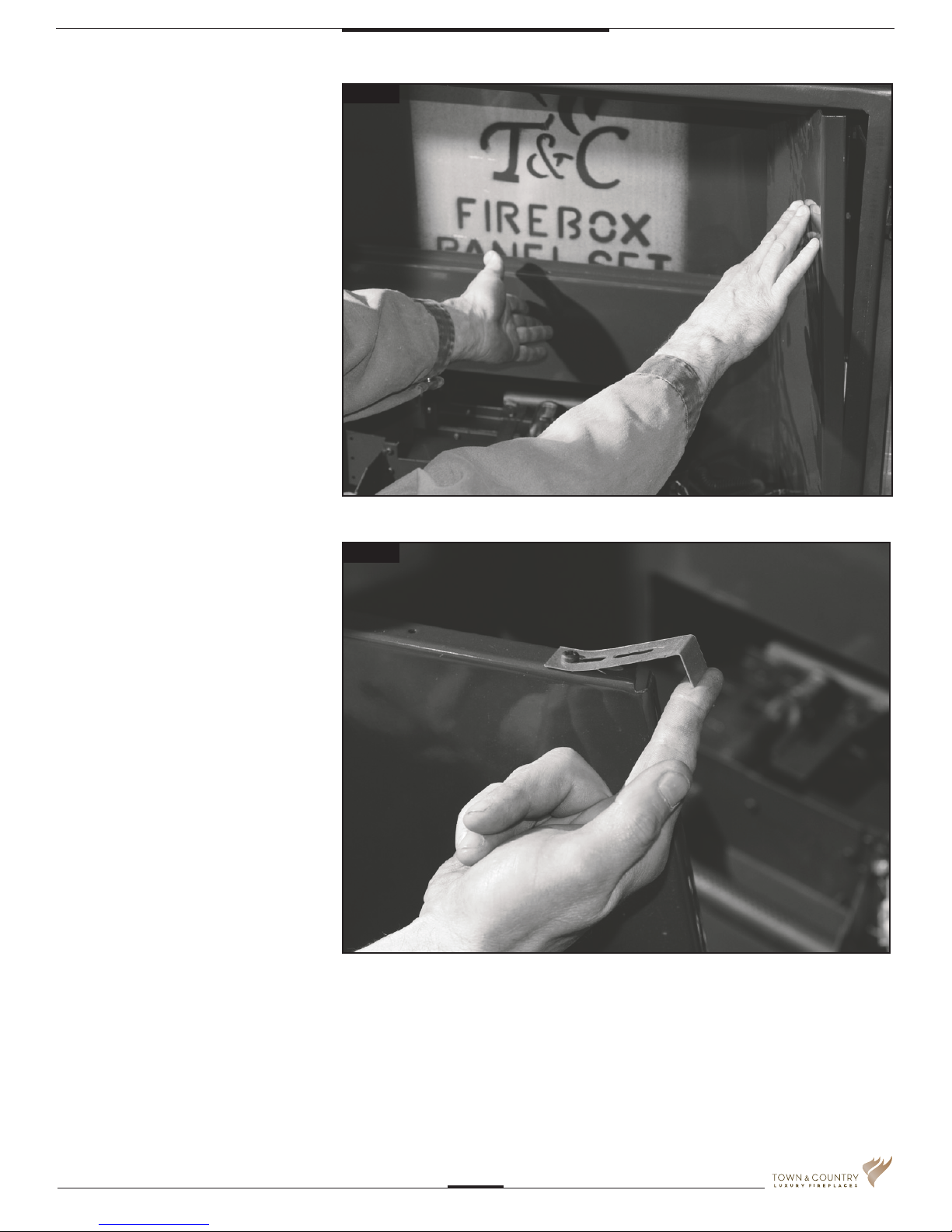
6. Remove panel retainer clips from upper
heat shield. Install right porcelain panel
tilting in from front corner. Secure the
right panel with one of the previously
removed panel retainer clips. (Fig #8)
Fig #8
7. Bend up retaining clip on the left panel.
Position upper rear panel on the top of
the lower rear panel and behind the right
panel. While supporting the upper rear
panel install and secure the left panel in
the same manner as the right panel.
(Fig #9)
Fig #9
TC30_ng04D_270315-16
5056.42904D
5
 Loading...