

Town & Country Fireplaces TC30, TC30.NG02.C Instructions Manual

INSTALLER: Leave this manual with the appliance.
CONSUMER: Retain this manual for future reference.
These instructions are supplementary to the Installation and
Operating Instructions supplied with the replace and should be
kept together. Refer to the Installation and Operating Instructions
for proper gas supply, safety requirements and operating
instructions
TC30
COUNTRY HOME
BURNER KIT
INSTRUCTIONS
100308-12 TC30.NG02.C 5056.429.02
PART#
TC30.NG02.C
For TC30 Series C
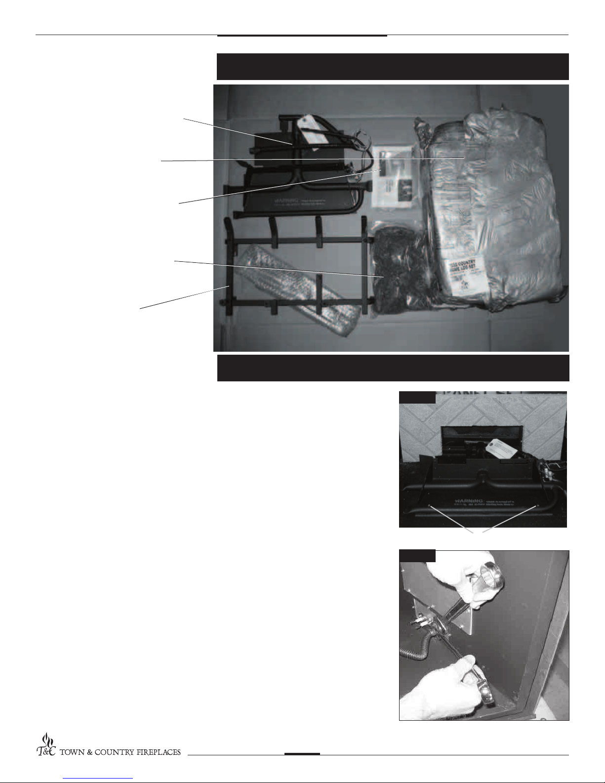
BURNER ASSEMBLY
7 PCS LOG SET
HARDWARE PACKAGE
EMBER MATERIAL
LOG GRATE
Contents of Package
Burner/Grate Installation
1. Attach the burner assembly to the oor of
the rebox with two screws. (Fig. # 1).
2. Attach the manifold supply tube to the
bulk head tting and tighten. (Fig. # 2)
Ensure that there are no leaks.
Fig #1
Fig #2
SCREWS
TC30.NG02.C 100308
2
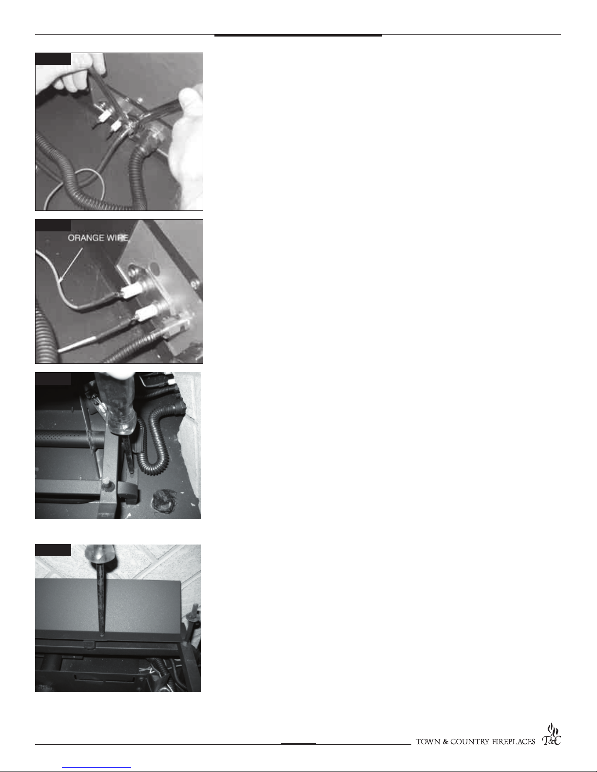
Fig #3
3. Attach the pilot supply tube to the bulk
head tting and tighten. (Fig. # 3)
Ensure there are no leaks.
Fig #4
Fig #5
4. Connect spark electrode wire
(ORANGE) to the rear electrical bulk
head tting. Connect the ame sensor
wire to the front electrical bulk head
tting. (Fig. # 4)
5. Position the grate over the burner tray
and attach to the oor with two screws
through holes located behind the front
legs of the grate.
(Fig. # 5)
Fig #6
TC30.NG02.C 100308
6. Attach air de ector to rear of grate with
two screws (Fig. # 6)
3
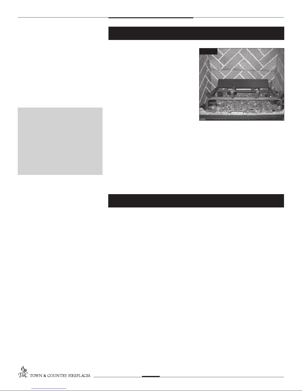
Ember Material
Note:
Ember material placement and
amount will affect ame appearance. More ember material results
in lower ame height. Add or
remove as needed until desired
ame affect is achieved.
Reduce the amount used on
Propane models, as too much will
create soot.
A large bag of ember material is shipped
with the replace and needs to be installed
to ensure optimum performance and ame
appearance.
1. Pull apart the material into ember size
pieces (approximately 1” squares) and
gently place them into the burner pan.
Do not compress, leave them loose for
best performance.
2. Fill the burner pan with embers until
level with the top of the pan at rear, and
gradually slope forward to the rebox
oor at the front, covering both burner
tubes.
3. Place remaining ember material outside
of the burner pan as desired to cover-up
gas lines and brackets.
Fig #7
Log Set Assembly
The logs are packaged in a foam pack inside the box. They are fragile and should be handled
with care. Unpack and inspect log set. There should be a total of 7 logs. Gas plumbing and
vent connections should be completed before proceeding.
Position the logs as indicated by the following pictures on page 5. The three main logs
have holes and /or pins. Engage each pin in the corresponding holes. The four smaller
logs do not have holes or pins. They rest in position. Locate as per the diagrams.
(Figs. #8 – #15)
TC30.NG02.C 100308
4
 Loading...