

Town & Country Fireplaces TC30 Black Diamond, TC30.NG03C Instructions For Use Manual

IMPORTANT:
THESE INSTRUCTIONS ARE TO REMAIN
WITH THE HOMEOWNER
These instructions are supplementary to the Installation
and Operating Instructions supplied with the replace
and should be kept together. Refer to the Installation
and Operating Instructions for proper gas supply, safety
requirements and operating instructions.
TC30
BLACK DIAMOND
BURNER KIT
INSTRUCTIONS
080411-20 TC30.NG03C 5056.42903
PART#
TC30.NG03C
For TC30 Series C
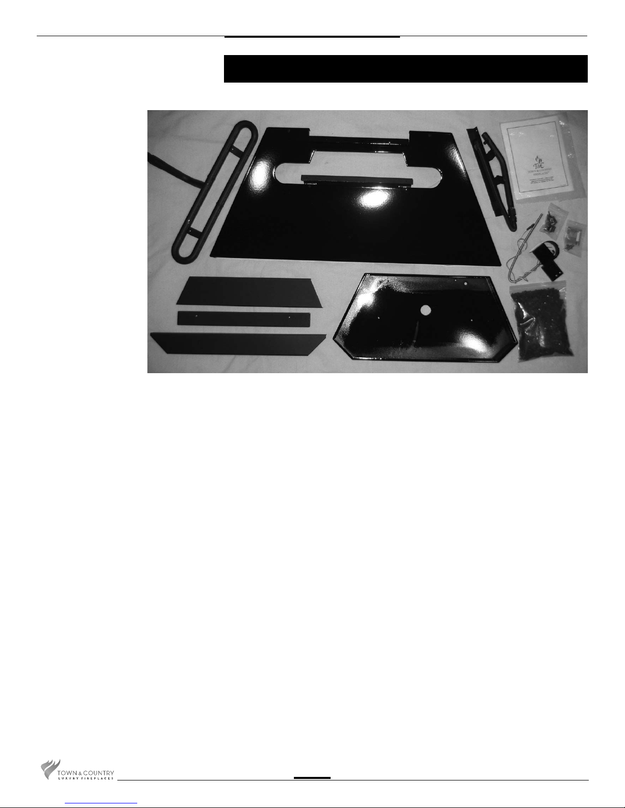
Contents of Package
A
B
C
F
D
E
NOTE:
MUST BE USED WITH PORCELAIN PANEL SET PART# TC30.PNLPBKB
A MANIFOLD ASSEMBLY
(including supply tube)
B BURNER TUBE
C BURNER SHIELD
D MEDIA SPACER, Center
E MEDIA SPACER, Front
F MEDIA SPACER, Rear
G HARDWARE PACKAGE
H 5 lbs. GLASS MEDIA
I BURNER TRAY
J PILOT SHIELD
(including pilot and pilot supply tube)
I
G
J
H
TC30.NGO3C 100308-20
2
Black Diamond Burner Installation
A porcelain panel set must be used
in conjunction with the installation of
the burner assembly. See Installation
and Operating Instructions manual for
details.
NOTE: Plug the 4 vacant holes in the
bottom of the rebox with 1/2” screws,
as they are not required to attach this
style of burner.
NOTE: If unit is to be converted to Propane,
see Propane conversion instructions on
page 7 before proceeding.
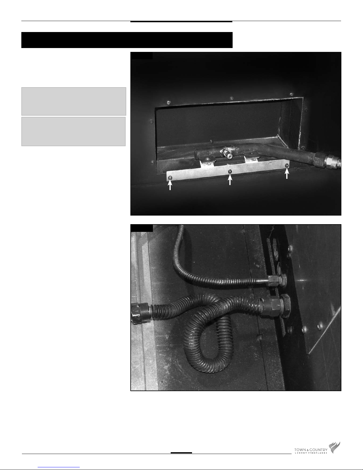
1. Remove three screws from the rear of
the rebox. Attach the manifold bracket
to the rear of the rebox with the three
screws previously removed. (Fig. #1)
Fig #1
2. Attach the manifold supply tube and the
pilot supply tube to the bulk head ttings
and tighten. (Fig. #2) Ensure that there
are no leaks.
Fig #2
TC30.NGO3C 100308-20
3
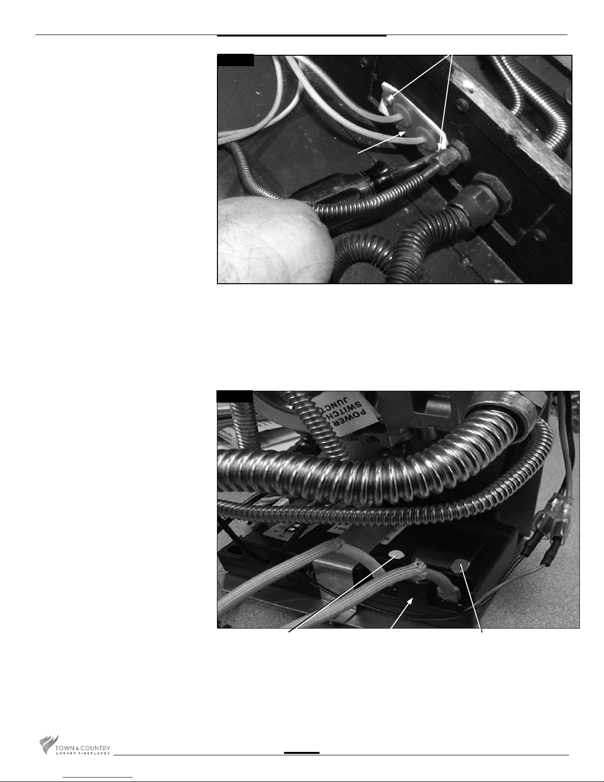
3. Secure the electrical bulkhead plate and
gasket to the rebox. (2 screws) Attach the
ignition and sensor wires to the module.
Red end to the connector marked by
the red dot, white end to the connector
marked by the white dot(Fig. #3 & 4)
2 SCREWS
Fig #3
BULKHEAD PLATE
Fig #4
WHITE END TO
WHITE DOT
MODULE
RED END TO
RED DOT
TC30.NGO3C 100308-20
4
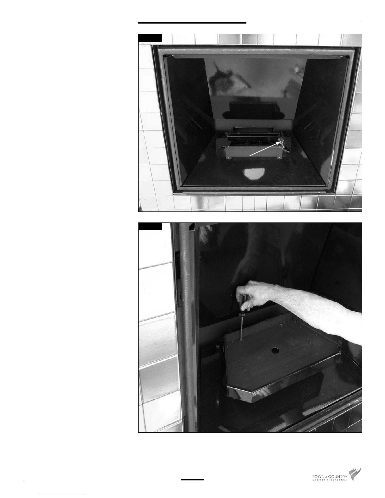
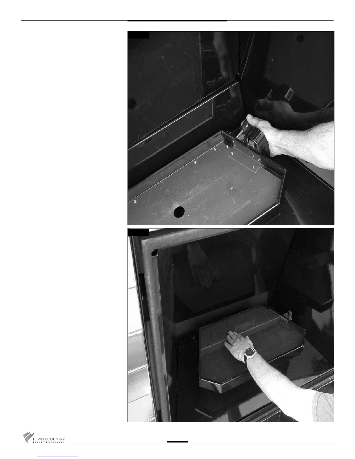
4. Install burner shield by tipping the shield
into the rebox. Route pilot up through
the opening in the burner shield.
(Fig. #5)
Fig #5
PILOT
5. Attach the burner tray to the burner shield
using two screws at the back of the tray.
(Fig. #6)
Fig #6
TC30.NGO3C 100308-20
5
6. Attach pilot shield to burner tray with two
screws. (Fig. #7)
Fig #7
7. Front and rear media spacers are now
installed. (Fig. #8 & 9)
Fig #8
TC30.NGO3C 100308-20
6
 Loading...