

Town & Country Fireplaces Model TC42SeriesC User Manual
Fireplace and Venting Speci cations
for
architects
designers
and
builders
IMPORTANT
This booklet is intended as a basic
speci cation guide for architects,
designers and builders. Please
refer to the Instruction Manual
supplied with the replace for
detailed information regarding
installation and operation.
Product installation manuals can
also be viewed at:
www.townandcountry replaces.net.
TC42
Series C
Model TC42 Series C
1 TC42.CE 080906-10
For reference only. Consult Manual before installation
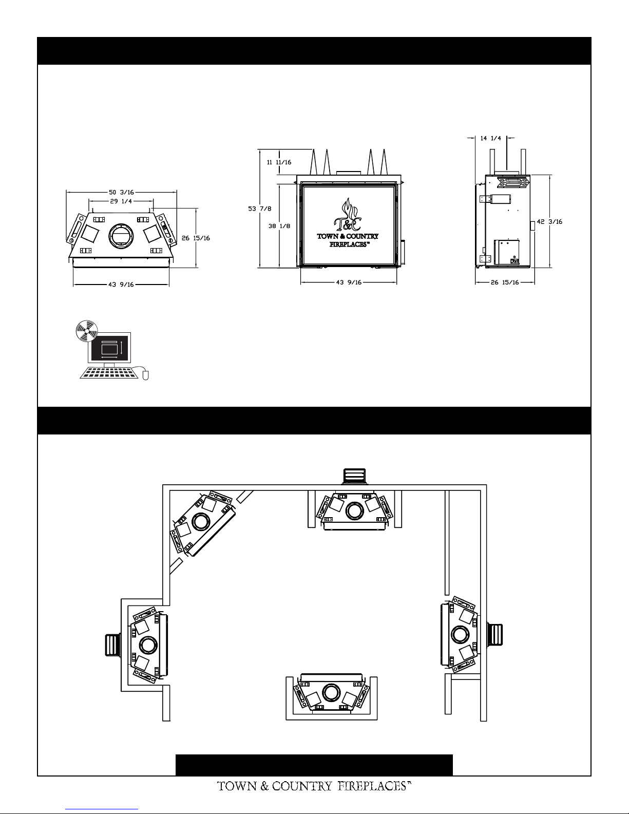
Fireplace Dimensions
TC42.CE Architect.dxf
Available on CD ROM and
www.townandcountry replaces.net
Examples of Common Locations
For reference only. Consult Manual before installation
2 TC42.CE 080906-10
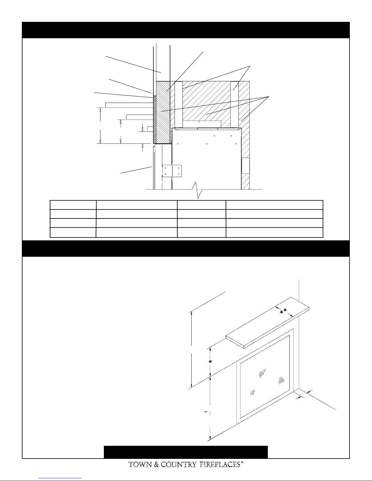
Mantel Clearance Chart
COMBUSTIBLE FRAMING
AND FINISH WALL ABOVE
STANDOFFS
MAY USE COMBUSTIBLE
FACING MATERIAL IN THIS
AREA
NON-COMBUSTIBLE
FINISH MATERIAL
A
TOP OF LINTEL BAR
FIREPLACE FRONT
REF. MANTLE CLEARANCE REF. MANTLE EXTENSION
A 9" D 12"
B 6" E 6 3/4"
C 3" F 1 1/2"
STEEL FRAMING
STANDOFFS
NON-COMBUSTIBLE ZONE.
D
E
F
B
DO NOT INSTALL ANY
COMBUSTIBLE MATERIAL,
ELECTRICAL WIRING,
INSULATION, PLASTIC
VAPOUR BARRIER OR
GAS PLUMBING IN THIS
AREA
C
Minimum Clearances to Combustibles
Side standoffs ...................... 0 in. (0 mm)
Back standoffs ..................... 0 in. (0 mm)
Top standoffs ....................... 0 in. (0 mm)
Bottom of appliance ............. 0 in. (0 mm)
Adjacent sidewall ................. 4 in. (102 mm)
Ceiling to appliance ........... 24 in. (610 mm)
Mantel to appliance .........................See above
*
**
Maximum mantel extension ..........See above
Horizontal vent pipe
Top ............................ 1-3/4 in. (45 mm)
Sides ........................ 1-3/4 in. (45 mm)
Bottom ...................... 1-3/4 in. (45 mm)
CEILING
24”
38 1/8”
MANTEL
UNIT MAY BE RECESSED UP TO
6" WITH NON-COMBUSTIBLE
MASONRY TYPE MATERIAL
ADJACENT
WALL OR
MANTEL
SUPPORT
4”
For reference only. Consult Manual before installation
3 TC42.CE 080906-10
 Loading...