

Town & Country Fireplaces HELIFIRE 360, HELIFIRE 360 SEE THRU Installation And Operating Instructions Manual

INSTALLER: Leave this manual with the appliance.
CONSUMER: Retain this manual for future reference.
WARNING: If the information in these
instructions is not followed exactly, a re or
explosion may result causing property damage,
personal injury or death.
HELIFIRE 360
FOR YOUR SAFETY
Installation and service must be performed
by a qualied installer, service agency or the
gas supplier.
WHAT TO DO IF YOU SMELL GAS
• Donottrytolightanyappliance.
• Donottouchanyelectricalswitch.
•Donotuseanyphoneinyourbuilding.
• Immediatelycallyourgassupplierfrom
a neighbour’s phone. Follow the gas
supplier’s instructions.
• Ifyoucannotreachyourgassuppliercall
the re department.
Do not store or use gasoline or other ammable
vapors and liquids in the vicinity of this or any
other appliance.
INSTALLATION
AND OPERATING
INSTRUCTIONS
This appliance may be installed in an aftermarket
permanently located, manufactured home (USA only)
or mobile home, where not prohibited by local codes.
This appliance is only for use with the type of gas
indicated on the rating plate. This appliance is
not convertible for use with other gases, unless a
certied kit is used.
This appliance is suitable for installation in a
bedroom or bed sitting room.
Visit www. townandcountryfireplaces.net for the most up-to-date version of this manual
280116-32 HELIFIRE 360 5055.64-A
MODEL: HELIFIRE 360
HELIFIRE 360 SEE THRU
POWER VENTED / DIRECT VENT
FIRE FEATURE - SERIES: A
NATURAL GAS ONLY

DANGER
Table of Contents
Caution ............................................................................3
Safety .............................................................................. 3
Owners Information
Important Note for the
Commonwealth of Massachusetts ................................ 4
Congratulations on your purchase
of a Town & Country Helifire 360 Feature .......................5
Helifire 360 Specifications .............................................5
Fire feature Dimensions ................................................. 6
Installation Requirements .............................................. 7
Door Frame Removal/Installation .................................. 7
Manufactured (Mobile) Homes ......................................7
First Fire .......................................................................... 8
Special Operator Note .................................................... 8
Locating the Helifire 360 ................................................ 8
Helifire 360 Orientation ................................................... 9
Installers Information
Framing and Finishing .................................................. 10
When using outdoor ashing .................................. 11
Framing Options ........................................................... 12
Gas Connection ............................................................ 14
Gas Supply ...................................................................14
Gas Pressure Testing Procedure .................................14
Gas Pressure Check ..................................................... 15
Burner and Igniter ........................................................ 15
Accessing / replacing the orice ............................. 15
Removing the Burner Control / Valve assembly ..... 16
Electrical Connection ...................................................18
Helire 360 electrical connection ............................ 18
Power vent electrical connection ............................ 18
Wall Switch .............................................................. 19
Electrical Diagram ........................................................ 20
Venting Requirements .................................................. 21
Exterior wall opening ............................................... 21
Vent Stand-Offs ....................................................... 22
Surface Mount Power Vent ..................................... 23
Combustion Air Intake Restrictor ............................ 23
Surface Mount Power Vent
(Vertical or horizontal termination). .......................... 24
Flush Mount Power Vent ......................................... 24
Stud Supports ......................................................... 25
Venting through combustible ceiling or oor .........25
Power venting - exible venting connection ........... 25
Exhuast venting options .......................................... 25
Vent Terminal Minimum Clearances ............................ 26
Power Venting
Clearances .............................................................. 26
Maintenance .................................................................27
Glass Panel ............................................................. 27
Periodically .............................................................. 27
Replaceable Parts ........................................................ 28
Lighting Instructions ..................................................... 29
Rating label ................................................................... 30
!
5055.64-A
HOT GLASS WILL CAUSE
BURNS.
DO NOT TOUCH GLASS UNTIL
COOLED.
NEVER ALLOW CHILDREN TO
TOUCH GLASS.
2
TCHF.22BODYA_ 151215-32
TCHF.22STBODYA

Owners Information
Caution
This appliance and its individual shut off valve must be disconnected
from gas supply piping system during any pressure testing of that
system at test pressures in excess of 1/2 psig (3.5 kPa).
This appliance must be isolated from the gas supply piping system by
closing its individual manual shut off valve during any pressure testing of
the gas supply piping system at test pressures equal to or less than 1/2
psig (3.5 kPa).
Owners Information
Note: When lit for the rst time, the appliance will emit a slight odour for
a couple of hours. This is due to the curing of paints, sealants and lubricants used in the manufacturing process. This condition is temporary.
Open doors and windows to ventilate area. Smoke and fumes caused
by the curing process may cause discomfort to some individuals.
Do not use the re feature if any part has been under water. Immediately
call a qualied service technician to inspect the re feature and to
replace any part of the control system and any gas control which has
been under water.
We recommend that our gas
hearth products be installed
and serviced by professionals who are certied in the
United States by the National
Fireplace Institute® (NFI) as
NFI Gas Specialists
Safety
Due to high temperatures, this gas appliance should be located out of trafc and away from furniture and
draperies.
Children and adults should be alerted to the hazards of high surface temperatures and should stay away to
avoid burns or clothing ignition.
Young children should be carefully supervised when they are in the same room as the appliance.
Toddlers, young children, and others may be susceptible to accidental contact burns. A physical barrier is
recommended if there are at-risk individuals in the house. To restrict access to a replace or stove, install
an adjustable safety gate to keep toddlers, young children, and other at-risk individuals out of the room and
away from hot surfaces. Clothing or other ammable material should not be placed on or near the appliance.
Any grill, panel or door removed for servicing the unit must be replaced prior to operating. Failure to do so
may create a hazardous condition.
Installation and repair should be done by a qualied service person. The appliance should be inspected
before use and at least annually by a professional service person. More frequent cleaning may be required
due to excessive lint from carpeting, bedding material, etc. It is imperative that control compartments, burners
and circulating air passageways of the appliance be kept clean.
It is our policy that no responsibility is assumed by the Company or by any of its employees or representatives
for any damages caused by an inoperable, inadequate, or unsafe condition which is the result, either directly
or indirectly, of any improper operation or installation procedures.
This appliance must not be connected to a chimney ue serving a separate solid fuel burning appliance.
TCHF.22BODYA_ 280116-32
TCHF.22STBODYA
3
5055.64-A

Owners Information
Important Note for the Commonwealth of Massachusetts
From Massachusetts Rules and Regulations 248 CMR 5.08:
(a) For all side wall horizontally vented gas fuelled equipment installed in every dwelling, building or structure used in whole or in part for residential
purposes, including those owned or operated by the Commonwealth and where the side wall exhaust vent termination is less than seven (7) feet
above nished grade in the area of the venting, including but not limited to decks and porches, the following requirements shall be satised.
1. INSTALLATION OF CARBON MONOXIDE DETECTORS. At the time of installation of the side wall horizontal vented gas fuelled equipment, the
installing plumber or gas tter shall observe that a hard wired carbon monoxide detector with an alarm and battery back-up is installed on the oor
level where the gas equipment is to be installed, in addition, the installing plumber or gas tter shall observe that a battery operated or hard-wired
carbon monoxide detector with an alarm is installed on each additional level of the dwelling, building or structure served by the side wall horizontal
vented gas fuelled equipment. It shall be the responsibility of the property owner to secure the services of qualied licensed professionals for the
installation of hard-wired carbon monoxide detectors.
a. In the event that the side wall horizontally vented gas fuelled equipment is installed in a crawl space or an attic, the hard-wired carbon monoxide
detector with alarm and battery back-up may be installed on the next adjacent oor level.
b. In the event that the requirements of this subdivision cannot be met at the time of completion of installation, the owner shall have a period of thirty
(30) days to comply with the above requirements; provided, however, that during said thirty (30) day period, a battery operated carbon monoxide
detector with an alarm shall be installed.
2. APPROVED CARBON MONOXIDE DETECTORS. Each carbon monoxide detector as required in accordance with the above provisions shall
comply with NFPA 720 and be ANSI/UL 2034 listed as IAS certied.
3. SIGNAGE. A metal or plastic identication plate shall be permanently mounted to the exterior of the building at a minimum height of eight (8) feet
above grade directly in line with the exhaust vent terminal for the horizontally vented gas fuelled heating appliance or equipment. The sign shall
read, in print size no less than one-half (1/2) inch in size, “GAS VENT DIRECTLY BELOW. KEEP CLEAR OF ALL OBSTRUCTIONS”.
4. INSPECTION. The state or local gas inspector of the side wall horizontally vented gas fuelled equipment shall not approve the installation unless,
upon inspection, the inspector observes carbon monoxide detectors and signage installed in accordance with the provisions of 248 CMR 5.089(2)
(a) 1 through 4.
(b) EXEMPTIONS. The following equipment is exempt from 248 CMR 5.089(2)(a) 1 through 4.
1. The equipment listed in Chapter 10 entitled “Equipment Not Required To Be Vented” in the most current edition of NFPA 54 as adopted by the
Board; and
2. Product Approved side wall horizontal vented gas fuelled equipment installed in a room or structure separate from the dwelling, building or structure
used in whole or in part for residential purposes.
(c) MANUFACTURER REQUIREMENTS – GAS EQUIPMENT VENTING SYSTEM PROVIDED. When the manufacturer of Product Approved side wall
horizontally vented gas equipment provides a venting system design or venting system components with the equipment, the instructions provided
by the manufacturer for installation of the equipment and the venting system shall include:
1. Detailed instructions for the installation of the venting system design or the venting system components; and
2. A complete parts list for the venting system design or venting system.
(d) MANUFACTURER REQUIREMENTS – GAS EQUIPMENT VENTING SYSTEM NOT PROVIDED. When the manufacturer of a Product Approved
side wall horizontally vented gas fuelled equipment does not provide the parts for venting the fuel gases, but identies “special venting systems”, the
following requirements shall be satised by the manufacturer.
1. The referenced “special venting system” instructions shall be included with the appliance or equipment installation instructions; and
2. The “special venting systems” shall be Product Approved by the Board, and the instructions for that system shall include a parts list and detailed
installation instructions.
(e) A copy of all installation instructions for all Product Approved side wall horizontally vented gas fuelled equipment, all venting instructions, all parts
lists for venting instructions, and/or all venting design instructions shall remain with the appliance or equipment at the completion of the installation.
5055.64-A
4
TCHF.22BODYA_ 280116-32
TCHF.22STBODYA
Owners Information
Congratulations on your purchase
of a Town & Country Helifi re 360 Feature
Your zero-clearance Heli re 360 re feature has been professionally installed by:
Dealer name: _____________________________________________
Phone Number: ___________________________________________
If you discover any problems with your Heli re 360 re feature contact your dealer immediately to have the
unit repaired.
Caution: Do not attempt to repair the Heli re 360 re feature because you may cause injury to yourself or others, and risk causing damage to the unit.
Before operating your Heli re 360 re feature carefully read this manual and pay close attention to all Safety
Warnings. The manual contains important information on the unit’s safe operation and maintenance.
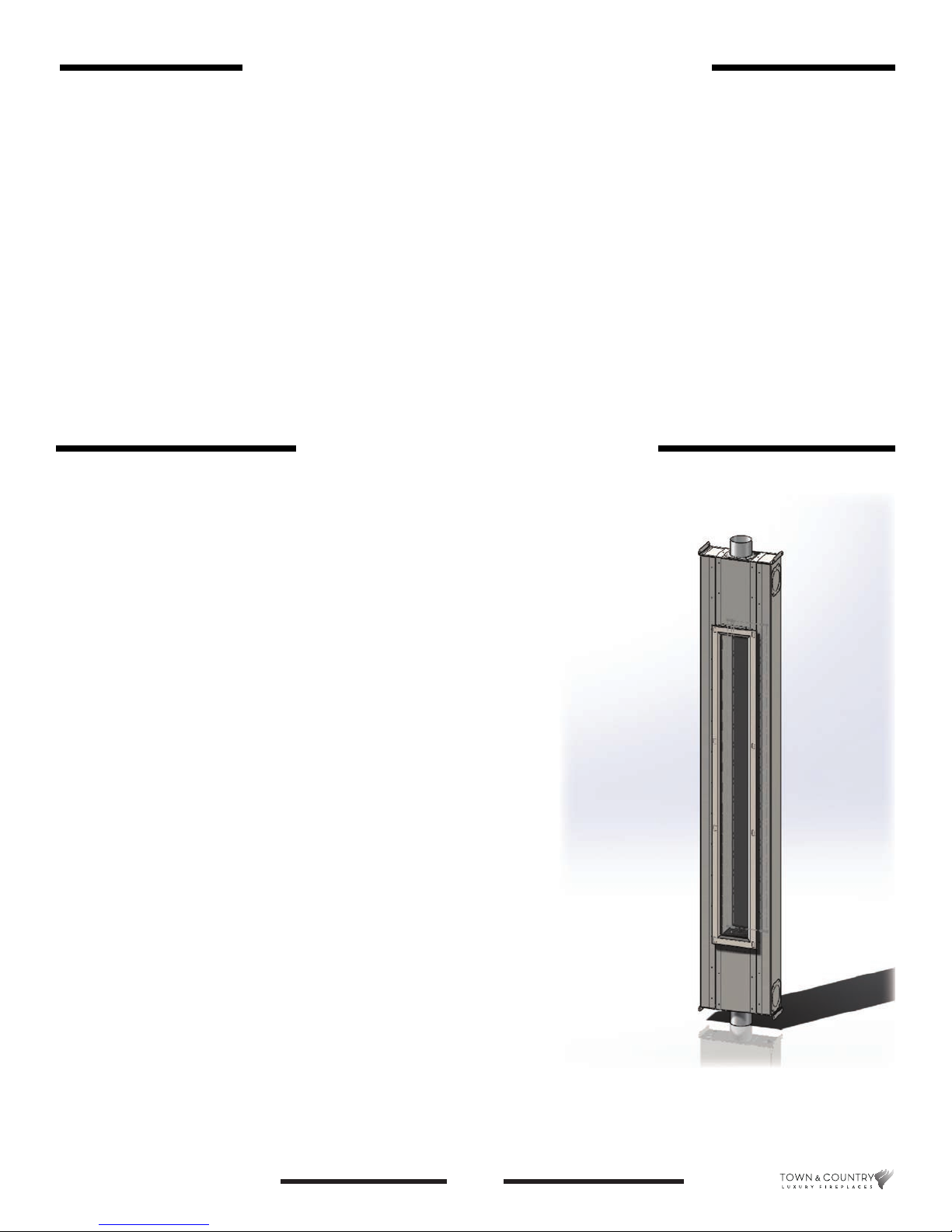
Helifi re 360 Specifi cations
Helifi re 360 multi orientational helical fl ame fi re feature.
Specifi cations
• 22,000 BTU/hr input ( xed input).
• Natural gas only.
• 24VAC honeywell direct ignition valve system.
• Power vented only. Either ush mounted power vent
(TCVT.PVFMA) or Surface mounted power vent (TCVT.
PVSMA) must be used. Vent extension kit (TCVT.PVEXTA)
contains 2 lengths of 25 foot exible venting pipe plus
adaptors. All of the above items are sold separately.
• 4” co-linear ex venting (1/4” clearance required).
• Multi exhaust position venting adaptors (1 position intake, 3
position exhaust).
• Heli re 360 unit is all 304 stainless steel construction.
• Zero clearance unit (no non-combustible board required).
• One sided and two sided (see through) units available.
• Units t within a 2” x 6” stud wall.
• Two sided unit has outdoor ashing option.
TCHF.22BODYA_ 280116-32
TCHF.22STBODYA
Figure 1: Heli re 360.
5
5055.64-A
Owners Information
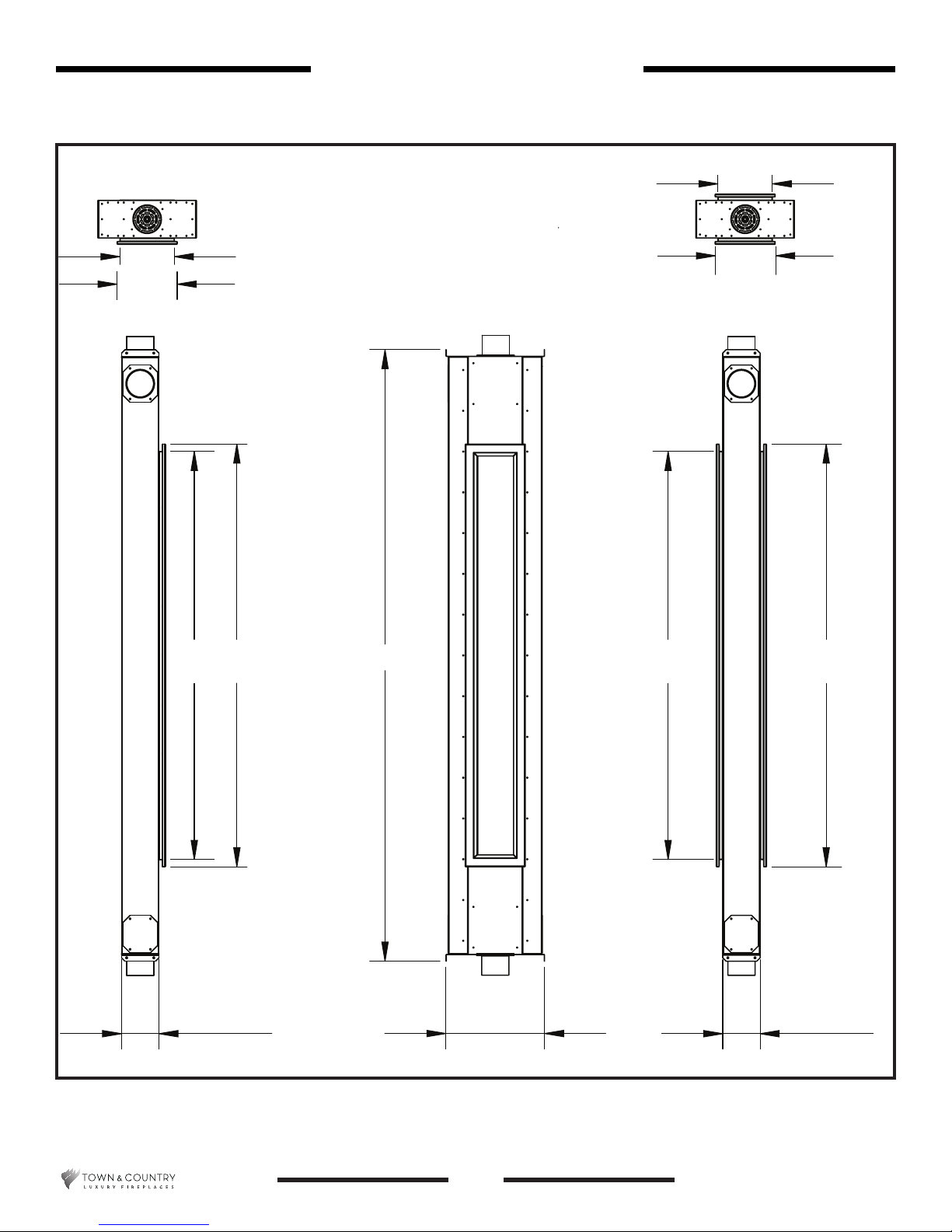
Fire feature Dimensions
One sided version Two sided version
8”
8”
8 7/8”
Side view
Top down view
60 1/8” 62 1/4”
90”
Top down view
8 7/8”
Front view Side view
60 1/8”
62 1/4”
5 1/2”
Figure 2: Helire 360 dimensions.
5055.64-A
14 1/2”
6
5 1/2”
TCHF.22BODYA_ 280116-32
TCHF.22STBODYA

Owners Information
Installation Requirements
The Helire 360 installation and venting must conform to the current CAN/CGA-B149 installation code (in
Canada) or the current National Fuel Gs Code, ANSI Z223.1 (in the USA), and approved per local codes.
Only qualied (licensed or trained) personnel should install this product.
In the state of Massachusetts, only a licensed Plumber and Gas Fitter may install this product.
Manufactured (Mobile) Homes
In some jurisdictions, the Helire 360 may be installed in Manufactured Homes after the “rst sale”. Consult
local codes for approval. The Heater must be fastened in place.
Install in accordance with the current standard Mobile Homes, CAN/CSA Z240 MH (in CANADA), and the
Manufacturer’s Home Construction and Safety Standard, Title 24 CFR, Part 3280 or the current Standard
for Fire Safety Criteria for Manufactured Home Installations, Sites and Communities ANSI/NFPA 501A (in the
USA).
Door Frame Removal/Installation
Warning: Turn off the Helire 360, and allow ample time for the unit to cool before proceeding.
Caution: The tempered glass is very fragile, and should be handled with care.
The Helire 360 door comes with a silicone seal and metal frame pre-assembled for easy mounting.
To replace a damaged door:
1. Remove the decorative trim from its magnetic holder.
2. Remove all 18 bolts from the door frame using the provided 5/32 Allen key. Be aware that the last bolt to
come out will allow the door frame to fall and keeping control of the door frame is crucial at this point.
3. Remove broken glass (if any) from the inside of the Helire 360.
4. Carefully position the replacement door frame against the Helire 360 and align the bolt holes.
5. Insert one bolt and then a second bolt on the opposite side of the frame in order to stabilize the frame.
Tighten them only nger tight at this point.
6. Insert the remaining bolts into the door frame. Tighten them only nger tight at this point.
7. Using the provided 5/32 Allen key (do not use a power driver), tighten the bolts so that the door frame
silicone seal is slightly compressed against the Helire 360 (about 1 1/2 turns past nger tight). Visually
inspect the door frame upon completion.
8. Return the decorative trim to its place on the Helire 360.
TCHF.22BODYA_ 280116-32
TCHF.22STBODYA
7
5055.64-A
Owners Information
First Fire
When lit for the rst time, the re feature may emit a slight odor for a couple of hours. This is due to the curing
of paints, sealants and lubricants used in the manufacturing process. This condition is temporary. Open
doors and windows to ventilate area. Odors caused by the curing process may cause discomfort to some
individuals. It is normal for replaces fabricated of steel to give off some expansion and/or contraction noises
during the start up or cool down cycle. Similar noises are heard from your furnace, heat exchanger or cook
stove oven.
Special Operator Note
NOTE: Fire feature may
take up to 30 seconds
to ignite each time the
“ON” button has been
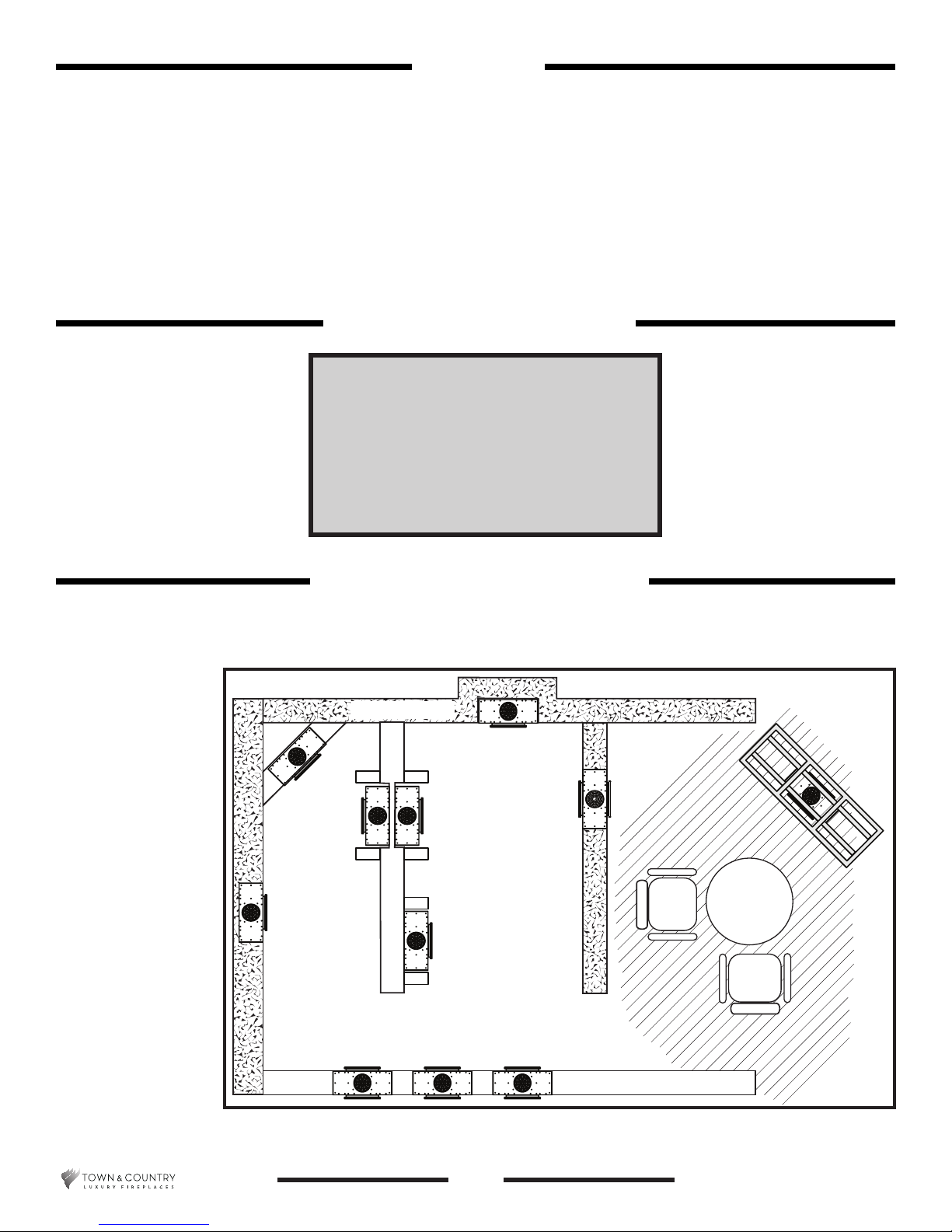
In planning for
the installation of
the Helire 360,
it is necessary to
determine where the
unit is to be installed,
location of vent
system and where gas
supply piping may be
plumbed.
Various types of installations are possible,
such as, a penisula
wall, island, and
between two interior
walls.
selected
Locating the Helifire 360
INSULATION
Figure 3: Locating the Helire 360.
5055.64-A
8
TCHF.22BODYA_ 280116-32
TCHF.22STBODYA
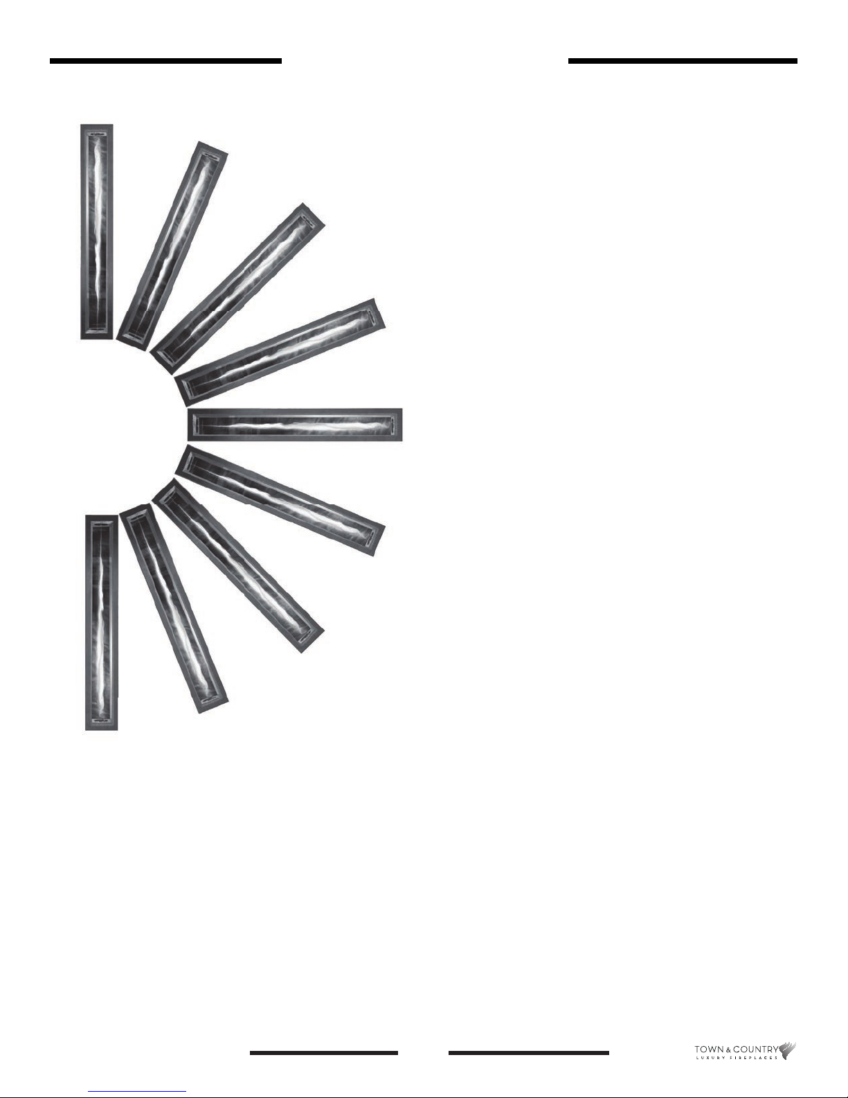
Helifi re 360 Orientation
The Heli re 360 is unique in that it can
be oriented in any position but must be
mounted so that the glass door is in a
vertical plane. The exception being that
the Heli re 360 cannot be installed at in
a oor or ceiling. The following should
be considered before deciding on a nal
position.
Owners Information
Figure 4: Orientation options.
• Flame length may vary by up to 30% due
to vent length and orientation.
• Vent exhaust pipe and air intake pipe
routing.
• Power vent terminal location.
TCHF.22BODYA_ 280116-32
TCHF.22STBODYA
9
5055.64-A

Installers Information
Installers Information
Framing and Finishing
Note: The Helifire 360 should be in place and venting installed before framing in or building an
enclosure around the unit.
Because of the relatively low temperatures radiating from the Helire 360, clearances from combustible
framing and facing materials are not such an issue as it would be if a traditional replace were being installed.
For this reason, combustible materials can be installed up to and ush with the decorative trim. Only a total
thickness of 1/2 inch facing material may be used. If preferred, 1/2 inch drywall can be used when using the
ashing option (Figure 10).
The finishing material must not interfere with glass frame access.
NOTE:
The chase must be properly sealed at the ceiling level or
between floors in a multilevel installation. This is for firestop purposes. See local building codes.
Vent Stand-offs
Vent stand-offs are used to maintain a 1/4 inch space between combustible surfaces and the exhaust
portion of the exible venting material. The exible venting material may come into direct contact with noncombustible material such as rockwool or cement board. See “Vent Stand-Offs” on page 22 for details.
Stud Supports
Stud supports for 2x6 studs are used to guide the exible venting from the re feature venting collar to the
power venting exhaust. See “Stud Supports” on page 25 for details
5055.64-A
10
TCHF.22BODYA_ 280116-32
TCHF.22STBODYA
 Loading...