

Town & Country Fireplaces Architectural Series, Architectural Peninsula, Architectural Panorama Installation Manual
INSTALLATION MANUAL
PENINSULA
INSTALLATION
MANUAL
FOR YOUR SAFETY
Installation and service must be performed by
a qualified installer, service agency or the gas
supplier.
WHAT TO DO IF YOU SMELL GAS
• Do not try to light any appliance.
• Do not touch any electrical switch.
• Do not use any phone in your building.
• Immediately call your gas supplier from a
neighbour’s phone. Follow the gas supplier’s
instructions.
• If you cannot reach your gas supplier call
the fire department.
Do not store or use gasoline or other
flammable vapors and liquids in the vicinity of
this or any other appliance.
This is a decorative product and is not intended
to be used as a heating appliance.
This appliance is suitable for installation in a
bedroom or bed sitting room.
This appliance may be installed in an aftermarket
permanently located, manufactured home (USA only)
or mobile home, where not prohibited by local codes.
This appliance is only for use with the type of
gas indicated on the rating plate. This appliance
is not convertible for use with other gases,
unless a certified kit is used.
WARNING: If the information in these instructions is
not followed exactly, a fire or explosion may result
causing property damage, personal injury or death.
INSTALLER: Leave this manual with the appliance.
CONSUMER: Retain this manual for future reference.
Architectural Series
100000847-50160819-52

Table of Contents
Caution ................................................................................. 3
Safety ................................................................................... 3
Important Note for the Commonwealth of Massachusetts .. 4
Congratulations on your Town & Country purchase ............. 5
Installation Requirements/Appliance Specications ............ 5
Installation Requirements ..................................................... 6
Vent Terminal Minimum Clearances ..................................... 6
Minimum Clearances to Combustible Material .................... 6
Appliance Dimensions ...........................................................7
Peninsula Dimensions using 16 inch High Glass ..............7
Peninsula Dimensions using 24 inch High Glass ............. 8
Btu Values and Weights ........................................................ 9
Minimum Clearances to Combustible Material .................... 9
Locating the Unit ................................................................ 10
Upper Support for Light Framed Units ................................11
Removing Vertical Supports ............................................... 12
Framing and Finishing ........................................................ 13
Framing .......................................................................... 14
Facing Material .............................................................. 15
Venting Conguration ......................................................... 16
Venting plenum .............................................................. 16
NOTE: Plenum must not be shared with
other appliances. .......................................................... 16
Venting Specications .........................................................17
Air Intake ............................................................................ 18
Optional Motorized Damper ............................................... 19
Power Vent ......................................................................... 20
Power Vent Dimensions ......................................................21
Vertical Installation ..............................................................21
Horizontal Installation ......................................................... 22
Vent Terminal Clearance ..................................................... 23
Power Vent Wiring .............................................................. 24
Flush Mount Power Vent Details ........................................ 25
Flush Mount Power Vent Dimensions ................................ 25
Mounting the Flush Mount Power Vent .............................. 26
Removing the grill .......................................................... 26
Installing the fan unit ...................................................... 26
Minimum Clearances to Combustibles .............................. 26
Framing the Flush Mount Power Vent .................................27
Flush Mount Electrical Connection .................................... 28
Bafe Adjustment ............................................................... 29
Glass Burner Tray and Media Installation ........................... 30
Burner tray installation ................................................... 30
Applying glass media ......................................................31
Window Frame Installation/Removal .................................. 32
LED Strip Replacement ...................................................... 34
Removing an LED section ............................................. 34
Electrical Connection ......................................................... 36
Electrical Diagram ...............................................................37
Control Panel Installation ................................................... 38
Installation instructions .................................................. 38
Gas Connection .................................................................. 43
Gas Pressure Requirements ............................................... 43
Lighting Instructions ........................................................... 44
Maintenance ....................................................................... 45
GLASS PANEL: .............................................................. 45
ANNUAL INSPECTION: ................................................. 45
Periodically: .................................................................. 45
Rating Labels ...................................................................... 46
2
100000847 160819-52Architectural Series

Caution
This appliance and its individual shut off valve must be disconnected from gas supply piping system
during any pressure testing of that system at test pressures in excess of 1/2 psig (3.5 kPa).
This appliance must be isolated from the gas supply piping system by closing its individual manual
shut off valve during any pressure testing of the gas supply piping system at test pressures equal to or
less than 1/2 psig (3.5 kPa).
Do not use the fire feature if any part has been under water. Immediately call a qualified service techni-
cian to inspect the fire feature and to replace any part of the control system and any gas control which
has been under water.
Power supply to the fireplace must be shut off before connecting or disconnecting the CAT5e cable to
the touch screen/toggle switch wall receptacle. This also applies to the touch screen charging cable.
We recommend that our gas hearth
products be installed and serviced
by professionals who are certified
in the United States by the National
Fireplace Institute® (NFI) as NFI Gas
Specialists
Safety
Any grill, panel or door removed for servicing the unit must be replaced prior to operating. Failure to do so
may create a hazardous condition.
Installation and repair should be done by a qualied service person. The appliance should be inspected
before use and at least annually by a professional service person. More frequent cleaning may be required
due to excessive lint from carpeting, bedding material, etc. It is imperative that control compartments,
burners and circulating air passageways of the appliance be kept clean.
It is our policy that no responsibility is assumed by the Company or by any of its employees or
representatives for any damages caused by an inoperable, inadequate, or unsafe condition which is the result,
either directly or indirectly, of any improper operation or installation procedures.
This appliance must not be connected to a chimney ue serving a separate solid fuel burning appliance.
160819-52 100000847
3
Architectural Series

Important Note for the Commonwealth of Massachusetts
From Massachusetts Rules and Regulations 248 CMR 5.08:
(a) For all side wall horizontally vented gas fueled equipment installed in every dwelling, building or structure used in whole or in part for residential
purposes, including those owned or operated by the Commonwealth and where the side wall exhaust vent termination is less than seven (7) feet
above nished grade in the area of the venting, including but not limited to decks and porches, the following requirements shall be satised.
1. INSTALLATION OF CARBON MONOXIDE DETECTORS. At the time of installation of the side wall horizontal vented gas fueled equipment, the
installing plumber or gas tter shall observe that a hard wired carbon monoxide detector with an alarm and battery back-up is installed on the oor
level where the gas equipment is to be installed, in addition, the installing plumber or gas tter shall observe that a battery operated or hard-wired
carbon monoxide detector with an alarm is installed on each additional level of the dwelling, building or structure served by the side wall horizontal
vented gas fueled equipment. It shall be the responsibility of the property owner to secure the services of qualied licensed professionals for the
installation of hard-wired carbon monoxide detectors.
a. In the event that the side wall horizontally vented gas fueled equipment is installed in a crawl space or an attic, the hard-wired carbon monoxide
detector with alarm and battery back-up may be installed on the next adjacent oor level.
b. In the event that the requirements of this subdivision cannot be met at the time of completion of installation, the owner shall have a period of thirty
(30) days to comply with the above requirements; provided, however, that during said thirty (30) day period, a battery operated carbon monoxide
detector with an alarm shall be installed.
2. APPROVED CARBON MONOXIDE DETECTORS. Each carbon monoxide detector as required in accordance with the above provisions shall
comply with NFPA 720 and be ANSI/UL 2034 listed as IAS certied.
3. SIGNAGE. A metal or plastic identication plate shall be permanently mounted to the exterior of the building at a minimum height of eight (8) feet
above grade directly in line with the exhaust vent terminal for the horizontally vented gas fueled heating appliance or equipment. The sign shall
read, in print size no less than one-half (1/2) inch in size, “GAS VENT DIRECTLY BELOW. KEEP CLEAR OF ALL OBSTRUCTIONS”.
4. INSPECTION. The state or local gas inspector of the side wall horizontally vented gas fueled equipment shall not approve the installation unless,
upon inspection, the inspector observes carbon monoxide detectors and signage installed in accordance with the provisions of 248 CMR 5.089(2)
(a) 1 through 4.
(b) EXEMPTIONS. The following equipment is exempt from 248 CMR 5.089(2)(a) 1 through 4.
1. The equipment listed in Chapter 10 entitled “Equipment Not Required To Be Vented” in the most current edition of NFPA 54 as adopted by the
Board; and
2. Product Approved side wall horizontal vented gas fueled equipment installed in a room or structure separate from the dwelling, building or structure
used in whole or in part for residential purposes.
(c) MANUFACTURER REQUIREMENTS – GAS EQUIPMENT VENTING SYSTEM PROVIDED. When the manufacturer of Product Approved side wall
horizontally vented gas equipment provides a venting system design or venting system components with the equipment, the instructions provided
by the manufacturer for installation of the equipment and the venting system shall include:
1. Detailed instructions for the installation of the venting system design or the venting system components; and
2. A complete parts list for the venting system design or venting system.
(d) MANUFACTURER REQUIREMENTS – GAS EQUIPMENT VENTING SYSTEM NOT PROVIDED. When the manufacturer of a Product Approved
side wall horizontally vented gas fueled equipment does not provide the parts for venting the fuel gases, but identies “special venting systems”, the
following requirements shall be satised by the manufacturer.
1. The referenced “special venting system” instructions shall be included with the appliance or equipment installation instructions; and
2. The “special venting systems” shall be Product Approved by the Board, and the instructions for that system shall include a parts list and detailed
installation instructions.
(e) A copy of all installation instructions for all Product Approved side wall horizontally vented gas fueled equipment, all venting instructions, all parts
lists for venting instructions, and/or all venting design instructions shall remain with the appliance or equipment at the completion of the installation.
4
100000847 160819-52Architectural Series

Congratulations on your Town & Country purchase
Your Architectural Series Zero Clearance linear appliance has been professionally installed by:
Dealer name: _____________________________________________
Phone Number: ___________________________________________
If you discover any problems with your linear appliance, contact your dealer immediately to have the unit
repaired.
Caution: Do not attempt to repair the linear appliance because you may cause injury to yourself or others,
and risk causing damage to the unit.
Before operating your linear appliance carefully read this manual and pay close attention to all Safety
Warnings. The manual contains important information on the unit’s safe operation and maintenance.
Installation Requirements/Appliance Specifications
Town and Country Architectural Series linear appliance.
Specifications
• This unit has been tested to ANSI Z21.50 and CSA P.4.1 specications.
• Single wall (min. 26 ga) galvanized venting. (Zero clearance)
• 120VAC / single phase.
• 24VAC Honeywell direct ignition valve system.
• Power vented only. Programmed with pre and post-purge safety functioning. Certied to use provided
Town & Country power vent only.
• Horizontal or Vertical Termination.
• Zero clearance unit (no non-combustible board required).
• 12” rigid exhaust - 150ft max length plus up to 6 elbows. (Zero clearance)
• 7” rigid intakes - ( All bottom intake models) 150ft max length plus up to 6 elbows. (Zero clearance)
•
• 12” or 14” rigid intakes - (All top intake models) 150ft max length plus up to 6 elbows. (Zero clearance)
160819-52 100000847
5
Architectural Series

Installation Requirements
The replace installation and venting must conform to the current CAN/CGA-B149 installation code
(in Canada) or the current National Fuel Gas Code, ANSI Z223.1 (in the USA), and approved per
local codes. Only qualied (licensed or trained) personnel should install this product.
In the state of Massachusetts, only a licensed Plumber and Gas Fitter may install this product.
Vent Terminal Minimum Clearances
Refer to the Power Vent installation instructions which are included with the power vent.
Minimum Clearances to Combustible Material
This appliance is a zero clearance re feature. Combustible material may be use to frame the unit in.
Venting for this unit is also zero clearance. Combustible material is permitted to come into direct
contact with venting material.
6
100000847 160819-52Architectural Series
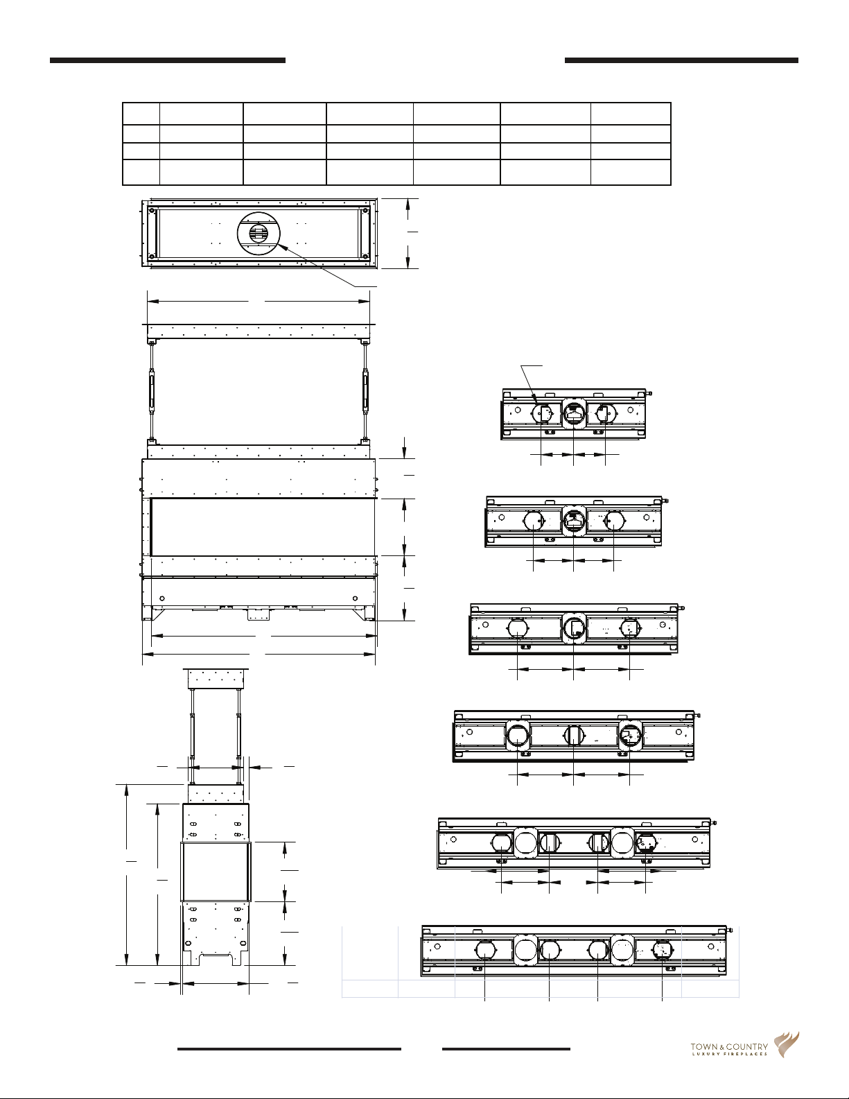
Appliance Dimensions
3’ 4’ 5’ 6’ 7’ 8’
A 51 1/2” 63 1/2” 75 1/2” 87 1/2” 99 1/2” 111 1/2”
B 53 1/4” 65 1/4” 77 1/4” 89 1/4” 101 1/4” 113 1/4”
C 50 1/4” 62 1/4” 74 1/4” 86 1/4” 98 1/4” 110 1/4”
Top view of replace
C
3
19
"
4
Ø11 7/8”
1
"
11
8
16"
1
" 18
8
Peninsula Dimensions using 16 inch
High Glass
Ø6 15/16”
12" 12"
15" 15"
505"
8
151"
2
1
4
5
"
8
A
B
21" 21"
1
1
"
2
9
" 16
" 45
16
13
16
" 17
1
" 18
2
21" 21"
18" 18" 18"
18" 24"
24"
160819-52 100000847
7
Architectural Series
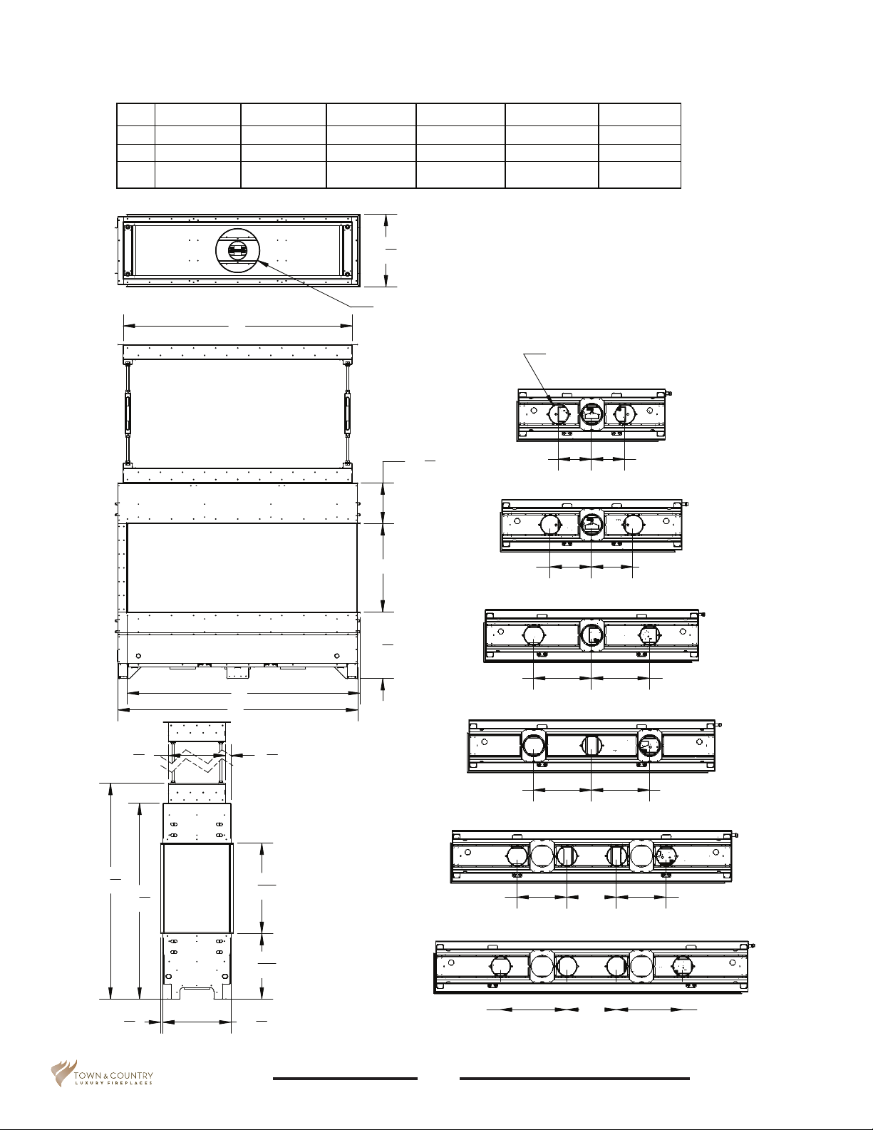
3’ 4’ 5’ 6’ 7’ 8’
A 51 1/2” 63 1/2” 75 1/2” 87 1/2” 99 1/2” 111 1/2”
B 53 1/4” 65 1/4” 77 1/4” 89 1/4” 101 1/4” 113 1/4”
C 50 1/4” 62 1/4” 74 1/4” 86 1/4” 98 1/4” 110 1/4”
Peninsula Dimensions using 24 inch
19
3
"
4
High Glass
Top view of replace
C
A
B
Ø11 7/8”
24"
1
18
8
"
11
Ø6 15/16”
1
"
8
12" 12"
15" 15"
21" 21"
58
1 1
"
15
2
5
"
8
1
"
53
4
5
"
8
24
17
18
"
1
2
21" 21"
9
"
16
13
16
1
2
"
24"
"
8
18" 18" 18"
18" 24"
100000847 160819-52Architectural Series
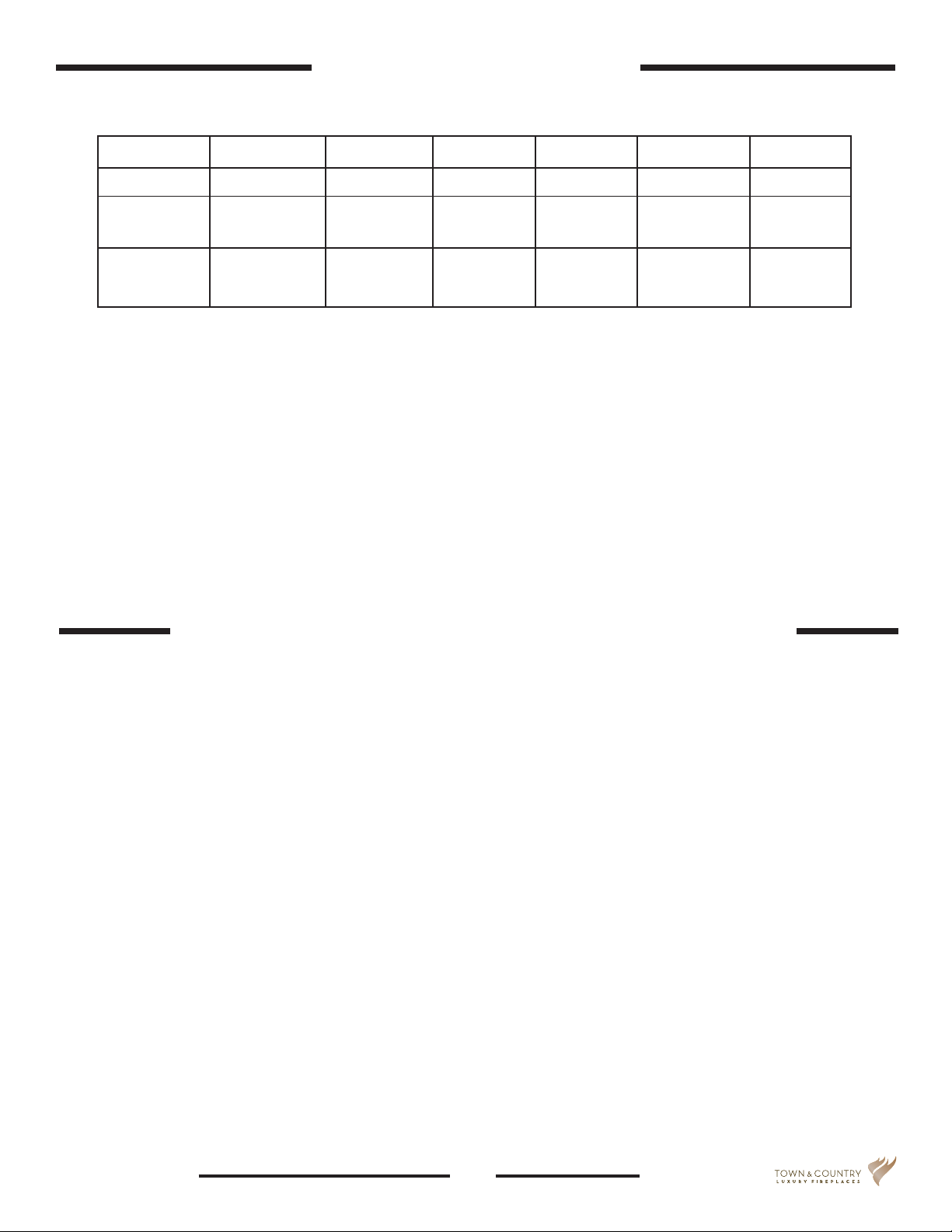
Btu Values and Weights
Peninsula 3FT 4FT 5FT 6FT 7FT 8FT
BTR/HR 48000 64000 80000 96000 112000 128000
24” Glass 470 540 610 680 750 820
16” Glass 500 570 640 710 780 850
Weight lbs
Weight lbs
Minimum Clearances to Combustible Material
This appliance is a zero clearance re feature.
Combustible material may be used to frame this unit in.
Venting for this unit is also zero clearance.
Combustible material is permitted to come into direct contact with venting material.
160819-52 100000847
9
Architectural Series
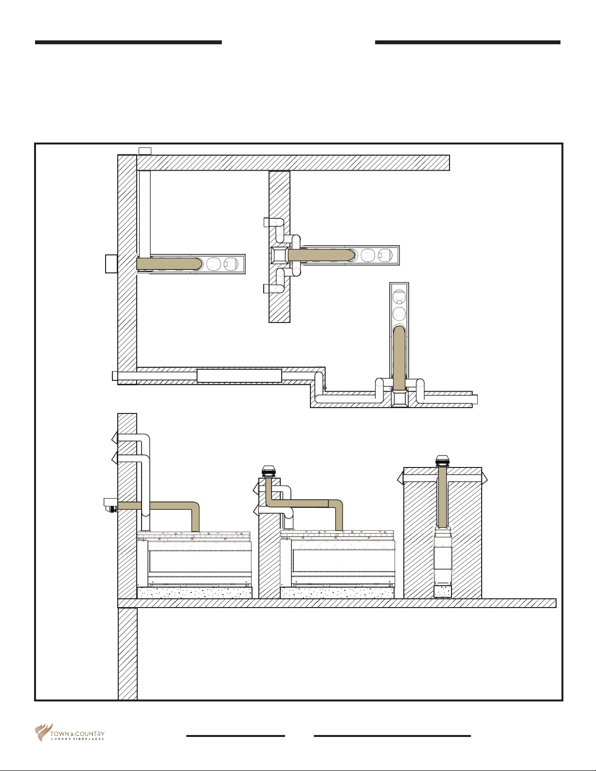
Locating the Unit
The Architectural Series Linear Appliances are power vent only, and because of this, they can be
located in a variety of places. Consideration must be taken for the location of the fresh air intake and
the power vent unit venting. A site fabricated platform capable of supporting the appliances weight
may be constructed to elevate the viewing area to the desired height, as well as accommodate the
fresh air intake - (if bottom vented), gas supply and electrical supply.
Power Vent
Air Intakes
Power Vent
Horizontal
Termination
Supporting wall
Vertical Termination
Vertical
Termination
Figure 1: Linear appliance location options.
10
100000847 160819-52Architectural Series
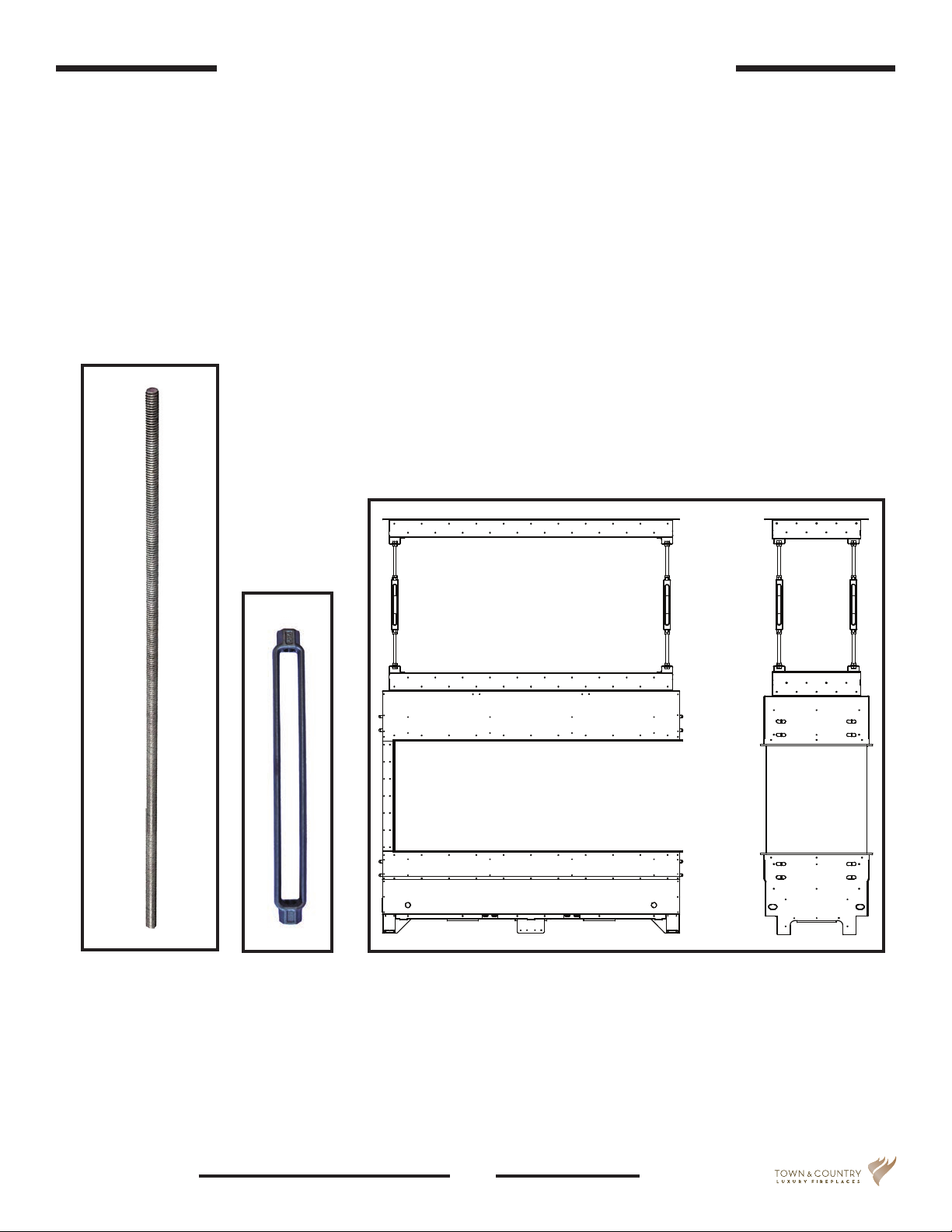
Upper Support for Light Framed Units
The Peninsula is built using either a light weight material or heavy weight material. The difference
between the two is determined by the weight of the facing material to be used. The lighter Peninsula
uses adjustable supports to support the upper section of the Peninsula so that its’ weight does not
distort the upper section of the Peninsula.
Materials included for this support include:
• Eight 6’ threaded rods - four right hand thread and four left hand thread (Figure 2).
• Four Turnbuckles (Figure 3).
Figure 2:
Threaded rod.
160819-52 100000847
Figure 3:
Turnbuckle.
Figure 4: Upper support frame and adjustable rods.
11
Architectural Series
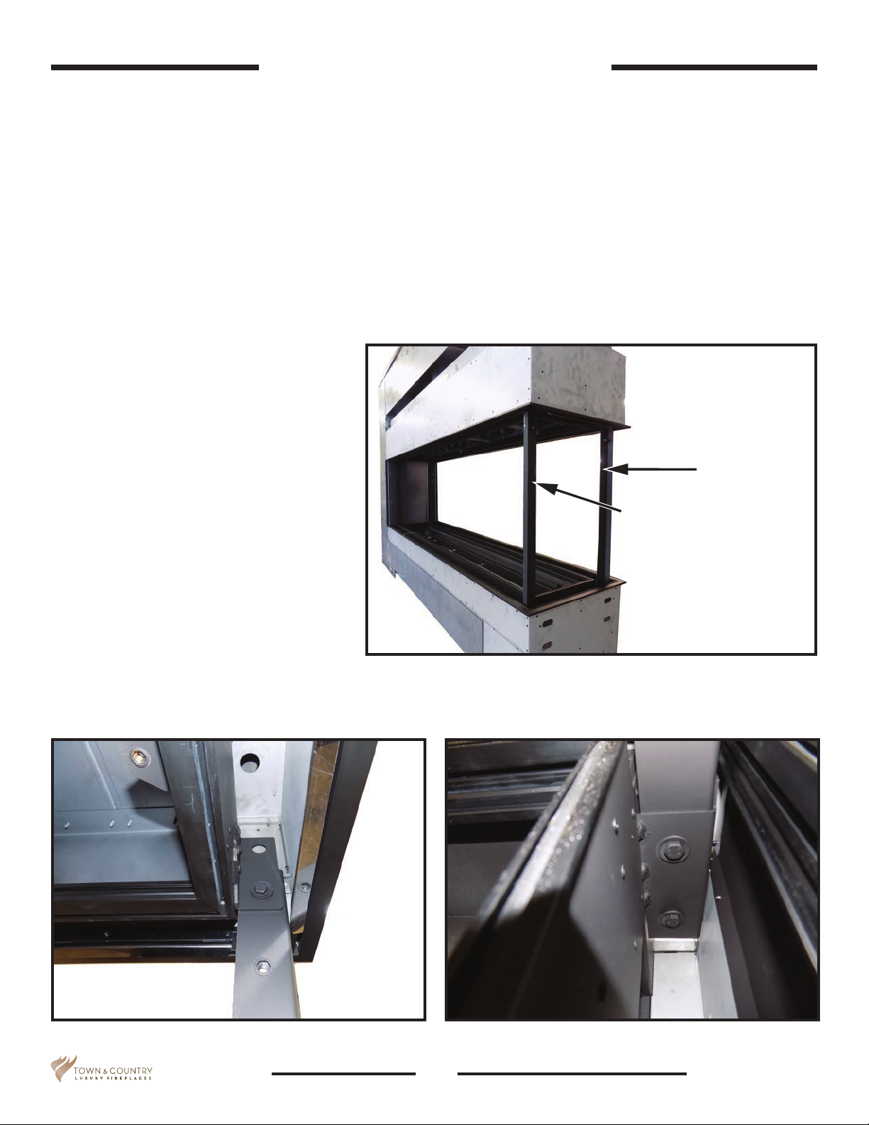
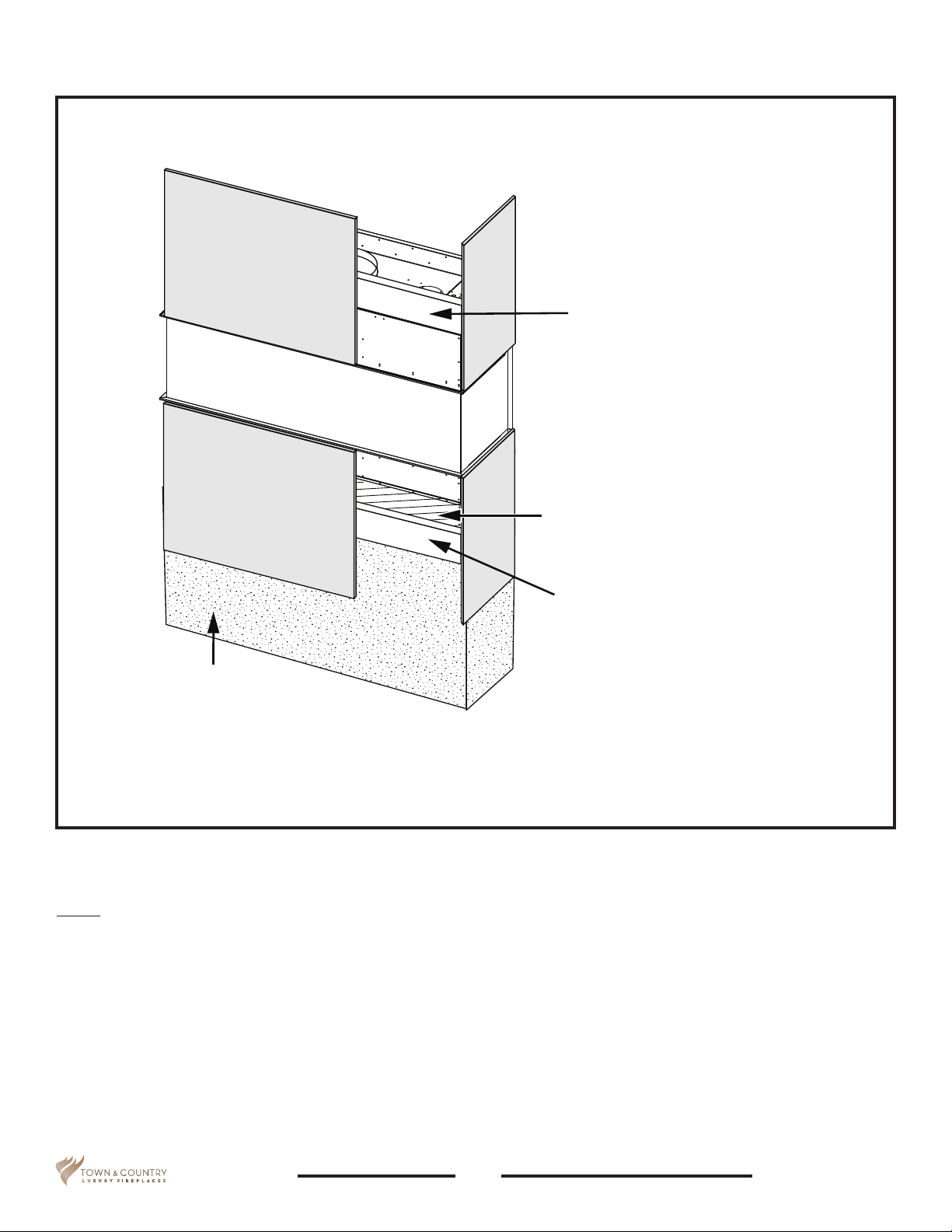
Removing Vertical Supports
Peninsulas built with a light frame ship with two vertical supports attached to the open end as
shown in Figure 5 so that the weight of the upper section of the replace does not distort the upper
section. These supports must remain in place until:
• The Peninsula is in its nal location.
• The Upper Support Frame is in its nal location.
• The adjustable turnbuckles and their threaded support rods have been set so that the upper
section of the Peninsula is no longer exerting weight on the vertical supports.
Once the weight of the upper section is fully supported by the adjustable support rods, the vertical
supports can be removed.
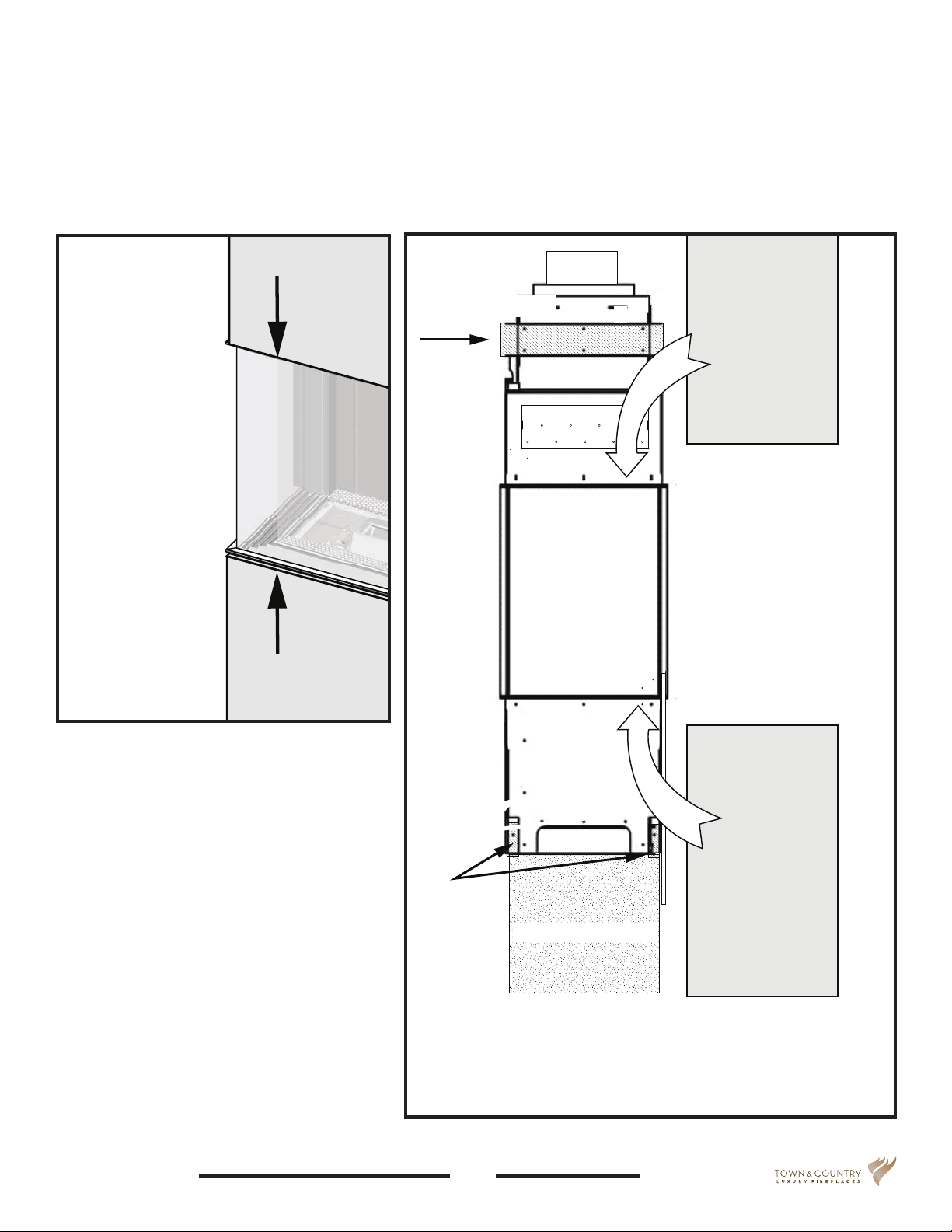
To remove:
Locate the bolts securing the vertical
supports to both the upper and lower
sections of the Peninsula (Figure 6
and Figure 7) .
Use a 9/16” socket wrench to remove.
Discard vertical supports once they
have been removed.
Vertical supports to be removed
once unit is in its nal position
Figure 5: Vertical supports to be removed.
Figure 6: Vertical support upper bolt to be removed. Figure 7: Lower support bolts to be removed.
12
100000847 160819-52Architectural Series
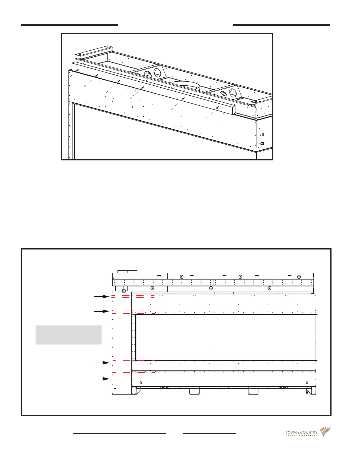
Framing and Finishing
2x4 framing lumber can be fastened to the
channel surrounding the top of the unit.
Figure 8: Stud securing points.
Before framing and nishing, there are two important points to keep in mind:
1. When securing wooden studs to the top of the unit, the screws can be secured through any part of
the upper fastening area surface (Figure 8).
2. Facing material can be secured directly to the front and sides of the unit except in the areas
indicated in this example in (Figure 9). Each model will have its own specic areas in which screws
must not be driven into.
Facing material may be screwed directly into the body of the
appliance with the exception of areas indicated.
1in. below rivets
3in. above trim
Do not use screws
in these areas
3in. below trim
Recessed area
(Long sides)
Figure 9: Facing attachment area.
160819-52 100000847
13
Architectural Series
Site fabricated platform
(must support 1200 lbs approx).
(Platform shown is for demonstration purposes only and
does not indicate how the structure should be constructed)
(Studs shown are for demonstration purposes
only and do not indicate how the nished
structure should be constructed)
Drywall or Facing
Material
2X4” Stud
Recessed Area (front & rear)
Drywall or Facing
Material
2X4” Stud
Figure 10: Framing and facing.
Framing
Note: To reduce vent noise, it is recommended to insulate the chase above the replace with soundproof
insulation.
Framing in the unit begins with determining how high from the oor the unit will sit. A platform capable of
supporting the weight of the unit and, if bottom air intake style, housing the fresh air intake venting must be
built. Standard 2X4”s or 2X6”s can be used for building the frame at the bottom of the unit and 2X4”s can be
used for building the frame at the top of the unit (Figure 10).
On the top of the unit, a pony wall can be built to the ceiling if desired. This pony wall will also accommodate
the exhaust venting material. Both supporting structure and pony wall must be tied into wall framing.
The building of the supporting structure and the pony wall must be built to local building codes.
14
100000847 160819-52Architectural Series
Facing Material
Because the appliance requires no clearance to combustible material, drywall or other facing mate-
rial can be afxed directly to the surface of the unit. Using standard 2x4’s and 2x6’s in the framing
process allows for the edge of 1/2” drywall or other facing material to t into the channels which
make up the perimeter of the exterior glass sheets (Figure 11 and Figure 12).
To Power Vent
Channels will
accommodate
1/2” Drywall or
Facing Material
Figure 11: Leading edge of drywall.
2X4” Studs
1/2” Drywall or
Facing Material
160819-52 100000847
2X4” Studs
Site fabricated platform
Figure 12: Left side framing and facing view.
15
Architectural Series
1/2” Drywall or
Facing Material
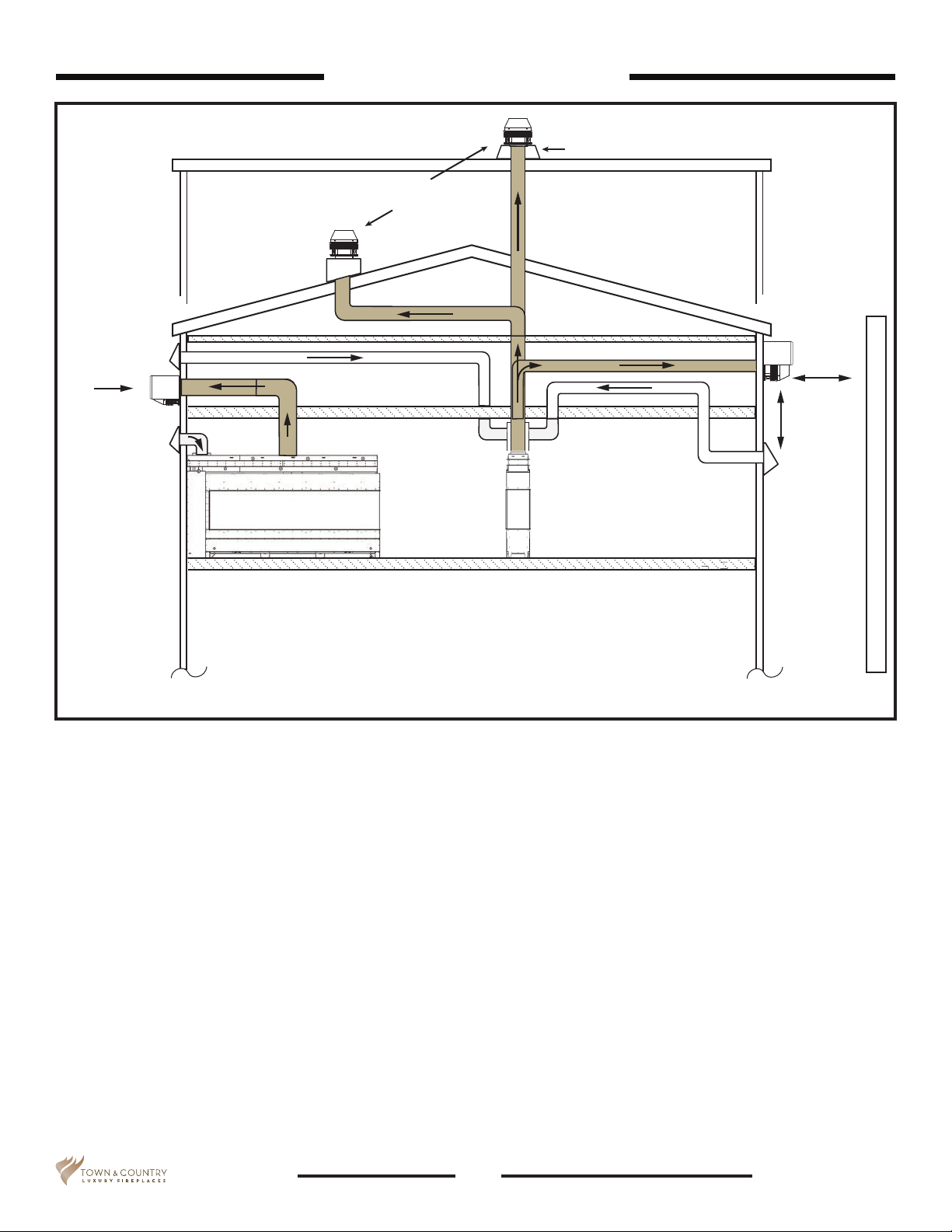
Surface mount
power vent
Flat roof conguration
Surface mount power vent
Peaked roof
conguration
Venting Configuration
Riser required
(Min. 12” high. Check local codes).
Direction of air ow
36 “ Min.
clearance
from
outlet
36 “ Min.
clearance
from intake
to outlet
Adjacent structure
Maximum ue outlet pipe length is 150 feet plus 6 elbows.
Maximum combustion air inlet pipe is 150 feet plus 6 elbows.
Figure 13: Venting congurations.
Venting plenum
NOTE: Plenum must not be shared with other appliances.
Some installations - particularly in new renovations or with pre-existing constraints /
obstacles may require the construction of a plenum in order to accommodate multiple air
intakes.
The plenum must be made of furnace ducting (Minimum 26 gauge) or other material
impervious to moisture. The constructed plenum must have a minimum cross-section of 150
square inches and be sealed to the air-intake collars on the appliance. The plenum may be
transitioned to a single intake as long as the 150 square inch cross-section is maintained.
For a single air intake, the rule of a maximum of 150 feet plus 6 elbows still applies.
16
100000847 160819-52Architectural Series
 Loading...