

Technical Data
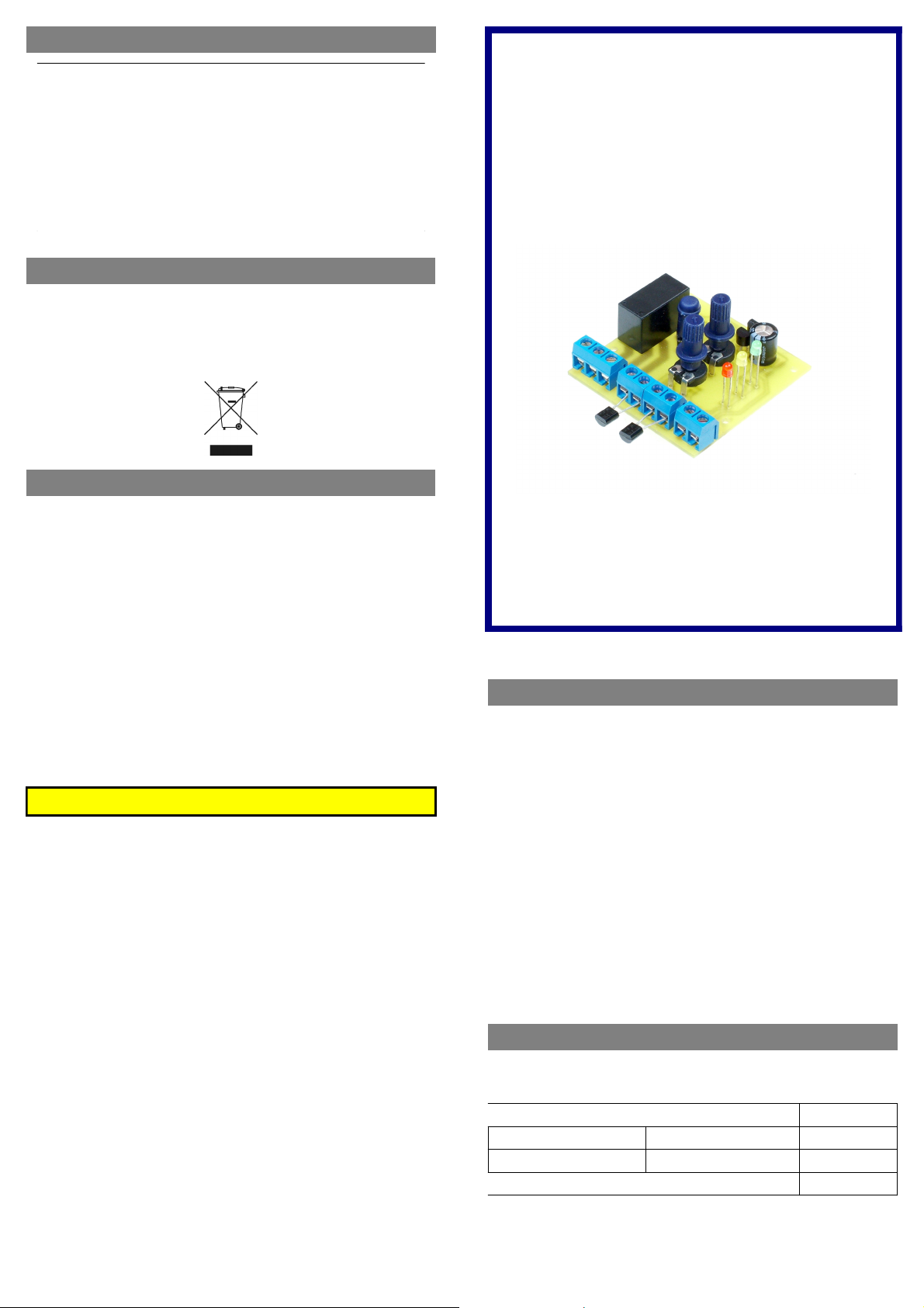
TowiTek differential temperature control module
Dimensions: 50 x 51 x 22 mm
Stromversorgung: 9-12V~(AC) or
@ 60mA max.
Rating for relay contact: 250VAC / 5A
Allowed environment temp.: 0°C .... 40°C (no condensing water)
Sensor specification: 2 x NTC 5kOhm @ 25°C B
Limit range for Sensor 1 min. 0...100°C
Limit range for t1-t2 0...20°C
12-15V= (DC)
25/85
= 3500
Disposal after end of using life for this product
Electronic devices of all kinds must not be disposed thru regular
household waste disposal but should be turned in to a collection
point for proper recycling. Please check with your local
requirements.
Limited Warranty
This product was designed and manufactured with great care and comes with a
warranty against material or manufacturing defects at time of purchase. This
warranty is valid for 24 months starting with the day of purchase and can be claimed
with original sales receipt. The warraty of TowiTek is limited to cost free repairing or
replacement of the defective unit. Expenses and risk of transportation; compensation
for installation and de-installation and all other expenses which may be related to the
repair or exchange of this product are not refunded by TowiTek. The liability for
consequential damages resulting from the use of this product – no matter of which
exact kind – is generally ruled out.
TowiTek
differential temperature
control module
Nr. 19 12 53
User Guide
www.conrad.com
Thank you for purchasing this product of TowiTek!
This user guide contains many important instructions on
safe and proper use of this product. The purpose of this
user guide is to make sure you always will get best
performance andan reliable operation of your new product.
PLEASE FULLY READ THIS USER GUIDE!
The handling of products operating with electric current requires you to
follow the rules from VDE such as VDE 0100, VDE0550/0551, VDE 0700,
VDE 0711 and VDE 0860 or other local rules in your country.
•
TowiTek modules are not designed and authorized for use in life support
or life saving applications! Do not use the product for applications in
which a temporary or permanent failure or malfunction could cause
damage to persons or propery.
•
If the module is used to switch currents greater 24V it is necessary to
have the installation done with no voltage applied and performed by a
trained professional authorized for such work. The module may only be
used in such application if it was installed in a safe to touch enclosure.
•
The module must only be used in dry and clean environment. The use
near water, heavy dirt and/or high humidity is dangerous and not
permitted.
•
The product must not be used in conjunction with any type of flammable
liquid or gas or other environment with risk of spark triggered
explosions.
•
Never exceed the limits or ratings listed in the 'Technical Data' section at
the end of this user guide.
•
If the module is used in schools or educational facilities or similar
institutions the operation must be supervised by trained and authorized
staff.
•
The product itself and all parts thereof (including packing material) are
not suitable toys for childern! (choking hazard, risk of electric shock, ...)
Intended of use for this product
The TowiTek differential temperature control module can be used for
many regulating applications for heating systems. Typical use for this
product is controlling circulation pump in various kinds of heating systems,
including solar heating systems.
Features of the
•
Connection of two temperature sensors (included with the product)
•
Two conditional rules for activating the output:
Condition #1: minimum temperature on Sensor 1 must be above
specified Limit (0...100°C)
Condition #2: temperature on Sensor 1 must exceed temperature on
Sensor 2 by at least specified Limit (0..20°C)
•
Manual mode for controlling the output without need to change limits
•
Easy adjustment of limits using rotary knobs
•
Digital signal processing with microcontroller using analog/digital
conversion for measuring signal inputs.
differential temperature control module
Operational instructions
Manual control of the relay output
button 'Manual Override' LED activity function
press about 0.5 sec. yellow on / red on override ON
again press about 0.5 sec. yellow on / red off override OFF
again press about 0.5 sec. yellow off or blinking normal mode
The manual override mode can be recognized by the yellow LED being
permanently lit and the red LED shoing the state of the output.
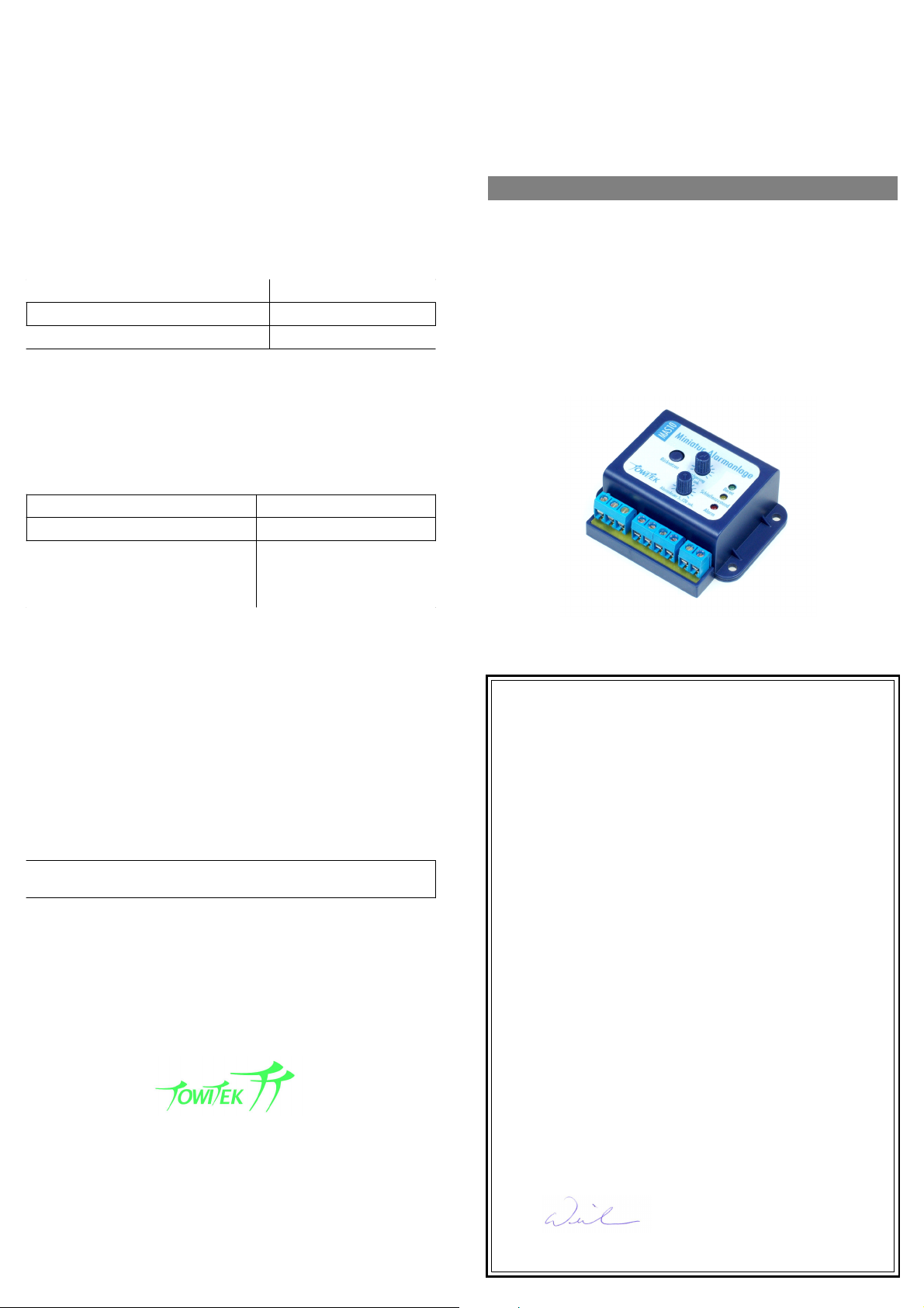
Normal operation mode
Picture with optional modular case order code 19 12 92
In normal operation mode two conditions are continuosly checked:
–
does the temperature on sensor 1 exceed the preset limit
–
does the difference of the temperatures on both sensors exceed the
preset limit (sensor 1 needs to be warmer than sensor 2)
If both conditions are met, the relay output is activated
Deactivation of condition checking
For both conditions to be checked it is possible to deactivate the limit
checking by setting the dial all the way to the left (0°C position).
In this case the limit is not set ot 0°C but this condition considered true
without checking the sensor readings
If both knobs are set to the left limit, both conditions are considered true
without reading the sensors and the relay will be activated
Temperature limit on Sensor 1
The upper dial is used to set a temperature limit from 0...100°C for
minimum temperature on Sensor 1. In normal mode it can be seen thru
LED status if the condition is met or not
mimimum temperature on Sensor 1 yellow LED activity
temperature does not exceed limit led blinking
temperature does exceed limit led off
Temperature difference between Sensor 1 / 2
The lower dial is used to set a minimum limit for the temperature
difference between both sensors in 0...20° range. In normal operation
mode the LED status will show if the condition is met or not
temperature difference T1-T2 red LED activity
difference smaller than preset limit red LED blinking
difference is greater than preset limit red LED off, yellow blinking
OR
red LED on, yellow LED off,
relay active
Assembly and mounting instructions
Assembly of the rotary knobs on the module
To to install the rotary knobs on the module with correct orientation of the
arrows it is recommended to first turn both potentiometers all the way to
the left firstly, removing the knobs again and re-insert with arrow pointing
at 'zero' position as shown on the printed front panel.
The differential temperature control module is designed to fit perfectly into
the TowiTek modular casing available with order number 19 12 92.
A printed and cut to shape front panel to fit on the case is supplied with
this product.
For use of this module with the modular casing a special knob to fit on the
switch plunger is included with this product.
The modular casing grants the touch safe enclosure which is required if
the module is to be used with mains current.
The modular casing comes with mounting clips to attach the case on
standardized DIN-mounting rails with 30 mm width.
The connection to the sensors can be extended as needed but the
maximum cable length should not exceed 15 meters for reliable operation.
The input terminals for the temperature sensors must not be
connected with any other voltage source!
FIND MORE PRODUCTS FROM
AVAILABLE AT
EU-Declaration of conformity
The company
TowiTek GmbH
Helenenstr. 21a
81825 München
declairs in solely own responsibility that the product
Differential temperatur control module 19 12 53
complies to the standards
EN 55022 (EMV emission)
EN 61000-6-1 (EMV tolerance)
The above named company keeps records
with confirm the compliance to the standards
www.conrad.com
19 12 53 ENG - REV 1.00 / 06.07
Tobias Wieler Munich, 11
th
of May 2007
 Loading...