

Page 1
INSTRUCTION MANUAL
®
WINGSPAN
100 in [2540 mm]
LENGTH
49.5 in [ 1257mm ]
Tower Hobbies® guarantees this kit to be free
from defects in both material and workmanship
at the date of purchase. This warranty does not
cover any component parts damaged by use or
modication. In no case shall Tower Hobbies’ liability
exceed the original cost of the purchased kit. Further, Tower
Hobbies reserves the right to change or modify this warranty
WARRANT Y
without notice.
In that Tower Hobbies has no control over the nal assembly or
material used for nal assembly, no liability shall be assumed nor accepted for any damage resulting from the use by the user of the nal user-assembled product. By the act of using the user-assembled product, the user accepts
all resulting liability.
If the buyer is not prepared to accept the liability associated with the use of this
product, the buyer is advised to return this kit immediately in new and unused condition
to the place of purchase.
To make a warranty claim, contact: airsupport @hobbico.com
14.1– 15.7 oz/ ft2 [43.0– 47.9 g/dm2]
READ THROUGH THIS MANUAL
WING AREA
616 sq in [39.7 dm2]
WING LOADING
BEFORE STARTING CONSTRUCTION.
INSTRUCTIONS AND WARNINGS
WEIGHT
3.8– 4.2 lb [1724–1905g]
RADIO
4+ Channel
IT CONTAINS IMPORTANT
CONCERNING THE ASSEMBLY
AND USE OF THIS MODEL.
TOWER HOBBIES
®
WARNING! This product may use a lithium polymer (LiPo) battery. Improper handling may result in FIRE! You are responsible for
following all safety precautions as outlined in this instruction manual.
© 2018 Tower Hobbies .® A subsidiary of Hobbico, Inc.
TOWA2045 v1.1
1
Page 2

TABLE OF CONTENTS
INTRODUCTION . . . . . . . . . . . . . . . . . . . . . . . . . . . . . . . . 2
AMA . . . . . . . . . . . . . . . . . . . . . . . . . . . . . . . . . . . . . . . . . . 2
SAFETY PRECAUTIONS . . . . . . . . . . . . . . . . . . . . . . . . . 2
ELECTRIC MOTOR SAFETY PRECAUTIONS . . . . . . . . 3
LITHIUM BATTERY WARNING!. . . . . . . . . . . . . . . . . . . . 3
REQUIRED ITEMS . . . . . . . . . . . . . . . . . . . . . . . . . . . . . . 4
Radio Components . . . . . . . . . . . . . . . . . . . . . . . . . . . 4
Battery and Charger . . . . . . . . . . . . . . . . . . . . . . . . . . 4
Adhesives and Building Supplies . . . . . . . . . . . . . . . .4
Optional Supplies and Tools . . . . . . . . . . . . . . . . . . . . 4
Covering Material. . . . . . . . . . . . . . . . . . . . . . . . . . . . . 4
Building Stand . . . . . . . . . . . . . . . . . . . . . . . . . . . . . . .5
ORDERING REPLACEMENT PARTS . . . . . . . . . . . . . . . 5
KIT INSPECTION . . . . . . . . . . . . . . . . . . . . . . . . . . . . . . .5
CONTENTS . . . . . . . . . . . . . . . . . . . . . . . . . . . . . . . . . . . . 5
PREPARATION . . . . . . . . . . . . . . . . . . . . . . . . . . . . . . . . . 6
WING ASSEMBLY. . . . . . . . . . . . . . . . . . . . . . . . . . . . . . . 6
As a new owner of an unmanned aircraft system (UAS), you
are responsible for the operation of this vehicle and the safety
of those around you. Please contact your local authorities
to nd out the latest rules and regulations.
In the United States, please visit:
knowbeforeyou y.org faa.gov/uas
INTRODUCTION
Congratulations on your purchase of the TOWER HOBBIES
Vista Grande powered glider! The Vista Grande is the largest
of the Tower Hobbies Vista sailplane series. The Grande
boasts a long 100" wingspan with a dedicated spoiler and
comes equipped with the powerful RimFire .32 (42-50-800)
brushless outrunner motor, 13.5 x 7 folding propeller and
capable 70A ESC that will get your glider to soaring altitude in
seconds! No need to bring along any launching equipment…
all you need is a charged up LiPo battery and you’re ready
for some thermal hunting. The huge wing area of the Vista
Grande will collect the rising air and your glider will coast
effortlessly for long ying sessions. When you’re ready to
land, ip a switch on your transmitter to raise the spoiler and
make the perfect touch down right on your target!
FUSELAGE ASSEMBLY . . . . . . . . . . . . . . . . . . . . . . . . . 10
GET THE MODEL READY TO FLY. . . . . . . . . . . . . . . . . 15
Check the Control Directions . . . . . . . . . . . . . . . . . . 15
Set the Control Throws . . . . . . . . . . . . . . . . . . . . . . . 15
Preparing to Balance the Model . . . . . . . . . . . . . . . . 16
Balance the Model Laterally . . . . . . . . . . . . . . . . . . . 17
Balance the Model (C.G.). . . . . . . . . . . . . . . . . . . . . . 17
PREFLIGHT . . . . . . . . . . . . . . . . . . . . . . . . . . . . . . . . . . . 18
Identify Your Model . . . . . . . . . . . . . . . . . . . . . . . . . . 18
Charge the Batteries . . . . . . . . . . . . . . . . . . . . . . . . . 18
Ground Check and Range Check . . . . . . . . . . . . . . . 18
SAFETY PRECAUTIONS . . . . . . . . . . . . . . . . . . . . . . . . 18
FLYING. . . . . . . . . . . . . . . . . . . . . . . . . . . . . . . . . . . . . . . 19
Mount the Wing . . . . . . . . . . . . . . . . . . . . . . . . . . . . . 19
Takeoff . . . . . . . . . . . . . . . . . . . . . . . . . . . . . . . . . . . . 19
Flight . . . . . . . . . . . . . . . . . . . . . . . . . . . . . . . . . . . . . 20
Landing . . . . . . . . . . . . . . . . . . . . . . . . . . . . . . . . . . . 20
way. There are over 2,500 AMA chartered clubs across the
country. Contact the AMA at the address or toll-free phone
number below.
Academy of Model Aeronautics
5151 East Memorial Drive
Muncie, IN 47302-9252
Tele. (800) 435-9262
Fax (765) 741-0057
Or via the Internet at: www.modelaircraft.org
IMPORTANT: Two of the most important things you can do
to preserve the radio controlled aircraft hobby are to avoid
ying near full-scale aircraft and avoid ying near or over
groups of people.
SAFETY PRECAUTIONS
Protect Your Model, Yourself & Others…
Follow These Important Safety Precautions
1. Your Vista Grande should not be considered a toy, but rather
a sophisticated, working model that functions very much like
a full-size airplane. Because of its performance capabilities,
this model, if not assembled and operated correctly, could
possibly cause injury to yourself or spectators and damage
to property.
AMA
We urge you to join the AMA (Academy of Model Aeronautics)
and a local R/C club. The AMA is the governing body of model
aviation and membership is required to y at AMA clubs.
Though joining the AMA provides many bene ts, one of the
primary reasons to join is liability protection. Coverage is not
limited to ying at contests or on the club eld. It even applies
to ying at public demonstrations and air shows. Failure
to comply with the Safety Code may endanger insurance
coverage. Additionally, training programs and instructors are
available at AMA club sites to help you get started the right
2. You must assemble the model according to the instructions.
Do not alter or modify the model, as doing so may result in
an unsafe or un yable model. In a few cases the instructions
may differ slightly from the photos. In those instances the
written instructions should be considered as correct.
3. You must take time to build straight, true and strong.
4. You must use an R/C radio system that is in rst-class
condition.
5. You must correctly install all R/C and other components
so that the model operates correctly on the ground and in
the air.
2
Page 3
6. You must check the operation of the model before every
ight to ensure that all equipment is operating and that the
model has remained structurally sound. Be sure to check
clevises or other connectors often and replace them if they
show any signs of wear or fatigue.
7. If you are not an experienced pilot or have not own this
type of model before, we recommend that you get the
assistance of an experienced pilot in your R/C club for
your rst ights. If you’re not a member of a club, your
local hobby shop has information about clubs in your area
whose membership includes experienced pilots.
8. While this model has been ight tested to exceed normal
use, if a motor larger than the one recommended is used,
the modeler is responsible for taking steps to reinforce the
high stress points and/or substituting hardware more
suitable for the increased stress.
WARNING: Drilling, sawing, sanding, or machining
wood products can expose you to wood dust, a
substance known to the State of California to cause cancer.
Avoid inhaling wood dust or use a dust mask or other
safeguards for personal protection. For more information
go to www.P65Warnings.ca.gov/wood
We, as the ARF manufacturer, provide you with a top quality,
thoroughly tested plane and instructions, but ultimately
the quality and yability of your nished model depends
on how you build it; therefore, we cannot in any way
guarantee the performance of your completed model,
and no representations are expressed or implied as to the
performance or safety of your completed model.
REMEMBER: Take your time and follow the instructions
to end up with a well-built model that is straight and true.
ELECTRIC MOTOR
SAFETY PRECAUTIONS
WARNING! A spinning propeller has the potential to cause
serious and permanent injury.
WARNING! Once the motor batteries are connected, the
propeller can start spinning at any time. Make sure the fail
safe is set on your radio to prevent the motor from starting
if the signal is lost.
WARNING! Stand clear of the propeller when handling
the aircraft. Make sure the aircraft is held securely until the
battery has been disconnected.
ALWAYS remove the propeller if the motor batteries will be
connected while working on your plane.
ALWAYS remove the motor batteries from the plane
when charging.
ALWAYS switch on the transmitter rst, then the receiver.
ALWAYS unplug the motor batteries rst before switching
off the receiver then transmitter.
NEVER touch the motor during or right after operation. The
motor gets HOT!
NEVER switch off the transmitter with the motor batteries
plugged in.
NEVER reach through the arc of the propeller when plugging
the battery into the ESC.
LITHIUM BATTERY WARNING!
This product requires the use of a lithium polymer
(LiPo) battery. Improper handling of a LiPo battery
could result in FIRE! A lithium battery re has the
potential to ignite surrounding areas and may cause property
damage or cause personal injury.
For safe LiPo handling, follow ALL of these guidelines:
MOST IMPORTANT! Never leave the battery or charger
unattended during charging or discharging.
WARNING: Read the entire instruction sheet included with
your motor batteries. Failure to follow the instructions could
cause permanent damage to the battery and its surroundings
and cause bodily harm!
ALWAYS follow the charging instructions included with your
charger for charging LiPo batteries. LiPo batteries can cause
serious damage or re if misused.
ALWAYS use a LiPo-approved charger.
ALWAYS set the charger’s output volts to match the
battery volts.
ALWAYS charge a LiPo battery in a reproof location.
ALWAYS balance charge the battery.
ALWAYS store and transport LiPo batteries in a reproof
container away from combustible materials.
ALWAYS KEEP OUT OF THE REACH OF CHILDREN.
ALWAYS keep LiPo batteries out of the reach of animals. A
punctured battery may cause a re.
ALWAYS disconnect the battery and unplug the charger
after the charge is complete.
ALWAYS keep a supply of sand accessible when charging
a LiPo battery. Dumping sand on the battery will assist in
extinguishing a LiPo chemical re.
ALWAYS remove the batteries from the plane after a crash.
Set them aside in a safe location for at least 20 minutes. If
the batteries are damaged in the crash, they could catch
re. If the battery starts to swell, quickly move the battery to
a safe location, preferably outside away from combustible
material. Place it in a bucket, covering the battery with sand.
NEVER use water to try and extinguish a LiPo re.
NEVER charge or use a battery that is deformed, bent,
crushed, swollen, or has any type of visible damage.
3
Page 4

NEVER use a NiCd/NiMH peak charger to charge a
LiPo battery.
NEVER charge in excess of 4.20V per cell unless the battery
is rated for a higher voltage.
NEVER charge at currents greater than 1C unless the battery
is rated for a higher charge rate.
NEVER trickle-charge a LiPo battery.
NEVER allow the battery temperature to exceed 140°F (60°C).
NEVER disassemble or modify the pack wiring in any way
or puncture the cells, as this may result in a re.
NEVER discharge below 3.2V per cell.
NEVER charge the battery or set the charger on combustible
materials.
NEVER charge the battery inside a vehicle or in a location
that could be damaged in the event of a LiPo re.
NEVER put a LiPo battery in the pocket of any clothing.
NEVER charge the batteries in the plane. Disconnect the
batteries and remove them from the plane immediately
after landing.
NEVER allow the battery to short circuit by touching exposed
wires together. This may cause a re.
NEVER operate or store batteries below 40˚F (4˚C) or above
110˚F (43˚C) ambient temperature.
Battery and Charger
The Vista Grande can use a 4S 14.8V 2200-3600mAh
LiPo battery. A smaller capacity battery will bene t you by
being lighter weight and the Vista will balance close to the
recommended C.G. without the need for ballast. A larger
battery will give you more motor power time but the glider will
y heavier with a more forward C.G. NOTE: There are many
other batteries that will t. Provided here are two batteries
with acceptable capacity and discharge rate.
❍ ONXP2269 LiPo 4S 14.8V 2200mAh 30C
❍ ONXP3363 LiPo 4S 14.8V 3600mAh 50C
A charger capable of charging LiPo batteries is required.
The Triton EQ (GPMM3155) is a suitable charger as it has
plenty of power for charging the LiPos recommended for the
Vista Grande (and larger LiPos as well). The Triton EQ is also
recommended for its versatility in charging all other types of
batteries used in RC and may be powered by either a 12V DC
power source or 110V AC. For an inexpensive alternative we
recommend the Onyx 225 (DTXP4225) charger. It is not as
feature packed as the Triton EQ but we like its easy-to-use
programming and digital display.
Adhesives and Building Supplies
REQUIRED ITEMS
Radio Components
At least 4 channels are needed to operate the Vista Grande
controls. Because the spoiler needs to be operated by a
switch, dial, or slider, we recommend the Tactic TTX610
transmitter as a capable, inexpensive radio system suitable
for this type of model. If it’s likely you will grow your radio
control interest beyond the Vista Grande in the future, we
recommend the TTX660. This is a computerized transmitter
which has a 30 model memory and several built-in mixing
functions along with programmable mixes and many other
convenient features. These functions will suf ce for most
types of radio control models in addition to the Vista Grande.
NOTE: The TTX610 includes the 6-channel receiver but it is
a separate purchase with the TTX660.
You’ll also need (2) 36mm long mini servos for the elevator
and rudder and (1) 23mm long micro servo for the spoiler.
NOTE: The opening in the plywood servo tray for the tail
servos can be lengthened some if the servos of your choice
are slightly longer than 36mm. A nylon servo tray for the
spoiler servo is included and will not accommodate a micro
servo longer than 23mm.
❍ TACJ2610 Tactic TTX610 6-Channel SLT System
(includes TR625 receiver)
❍ TACJ2660 Tactic TTX660 6-Channel Computer
Transmitter (does not include receiver)
❍ TACL0625 Tactic TR625 6-Channel SLT Receiver
❍ TACM0220 Tactic TSX20 Mini High-Speed 2BB Servo
❍ TACM0205 Tactic TSX5 Micro High-Speed Servo
❍ FUTM0004 Futaba S3004 Standard Ball Bearing Servo
❍ FUTM0414 Futaba S3114 Micro High-Torque Servo
❍ Tower Hobbies 6-minute Epoxy (TOWR3806)
❍ Tower Hobbies 30-minute Epoxy (TOWR3810)
❍ Mixing Sticks (50, GPMR8055)
❍ Mixing Cups (GPMR8056)
❍ Epoxy Brushes (GPMR8060)
❍ Tower Hobbies Build-It CA Thin Glue (TOWR3800)
❍ Tower Hobbies Build-It CA Medium Glue (TOWR3801)
❍ Denatured Alcohol (for epoxy clean-up)
❍ Masking Tape
❍ 1/16" [1.5mm], 5/64" [2mm], 3/32" [2.5mm] drill bits
❍ Drill
❍ Phillips Head Screwdriver
❍ Wire Cutters
❍ Pliers
❍ Stick-on Segmented Weights (GPMQ4485)
❍ CG Machine (GPMR2400)
❍ Paper Towels
❍ #1 Hobby Knife (RMXR6903)
❍ #11 Blades (5-pack, RMXR6930)
❍ Clamp
Covering tools
❍ Top Flite MonoKote Sealing Iron (TOPR2100)
❍ Top Flite Hot Sock Iron Cover (TOPR2175)
❍ Top Flite MonoKote Trim Seal Iron (TOPR2200)
❍ Top Flite MonoKote Heat Gun (TOPR2000)
❍ Coverite 21st Century Sealing Iron (COVR2700)
❍ Coverite 21st Century Cover Sock (COVR2702)
❍ Coverite 21st Century Trim Sealing Iron (COVR2750)
4
Page 5
Optional Supplies and Tools
IMPORTANT BUILDING NOTES
Here is a list of optional tools that will help you build the
Vista Grande.
❍ CA Applicator Tips (HCAR3780)
❍ CA Debonder (GPMR6039)
❍ Servo Horn Drill (HCAR0698)
❍ AccuThrow De ection Gauge (GPMR2405)
❍ Precision Magnetic Prop Balancer (TOPQ5700)
Covering Material
The lm covering on this model is not a product that is
packaged and sold separately. Fortunately, if you need to
repair the covering on your Vista Grande, TopFlite MonoKote
offers colors that are a close match and are readily available
from Tower Hobbies or your local R/C hobby supplier. The
rolls are sold in either 6' or 25' lengths (part numbers for
the 6’ lengths are provided below) and are great to keep on
hand for quick repairs. Please note: These colors are not a
perfect match. We recommend replacing damaged covering
in complete “panels” so the slight difference in color shades
between the original covering and the MonoKote cannot be
seen. For example, if the red wing tip becomes damaged,
replace all of the red covering on that wing tip.
Missile Red 6' (TOPQ0201)
Jet White 6' (TOPQ0204)
Aluminum 6' (TOPQ0205)
Sky Blue 6' (TOPQ0206)
● Anytime a sheet metal screw is installed in wood, rst
install the screw, remove the screw and apply a couple of
drops of thin CA in the hole to harden the threads. After
the CA has cured, reinstall the screw.
● Photos and sketches are placed before the step they
refer to. Frequently you can study photos in following steps
to get another view of the same parts.
● You will see this symbol anytime cyanoacrylate
glue is required.
.
● You will see this symbol anytime a threaded
screw or nut is installed.
● You will see this symbol anytime
epoxy is recommended.
● Anytime a hole needs to be drilled you will see
this symbol with the recommended size drill bit.
● When you see this symbol, use a glue of your
choice.
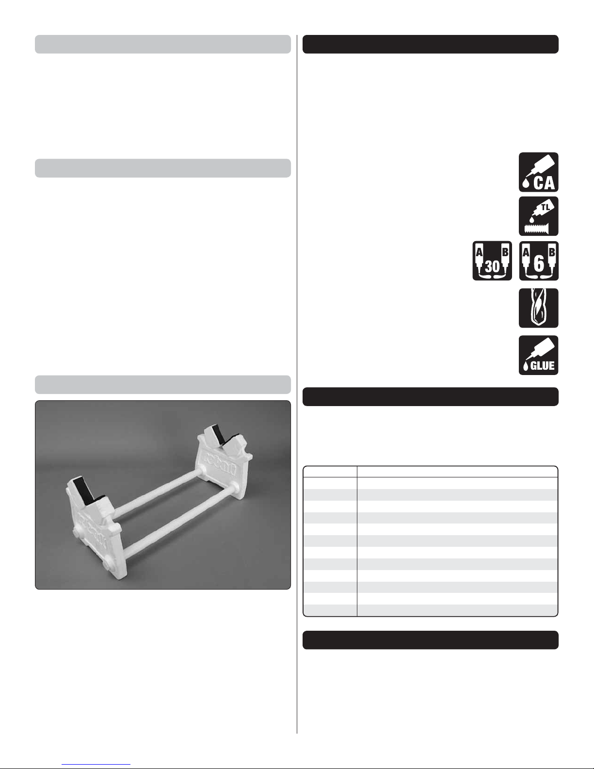
Building Stand
A building stand or cradle comes in handy during the build.
We use the Robart Super Stand II (ROBP1402).
ORDERING REPLACEMENT PARTS
Replacement parts are available from Tower Hobbies for
your Vista Grande. Our order assistance representatives are
ready to answer your questions or to place your order. Call
us at (800) 637-6050.
Order No. Description
TOWA2081
TOWA2082
TOWA2083
TOWA2084
TOWA2085
TOWA2086
GPMA5307
GPMA5308
GPMA5310
GPMA5311
GPMG4700
GPMM2160
Wing
Fuselage
Tail Surface Set
Canopy
Decals
Spoiler Hardware Set
Propeller Adapter
Spinner Set
Complete Folding Propeller Set
Folding Propeller Blade Set 13.5" x 7
Great Planes RimFire .32 42-50-800 Outrunner Brushless
60A 2S-6S Programmable 5V BEC ESC
KIT INSPECTION
If any parts are missing or damaged, consult Tower Hobbies
Order Assistance.
Note: All parts are one per kit unless otherwise stated.
Toll Free Order Assistance . . . . .800 637-6050
or airsupport@hobbico.com
5
Page 6
CONTENTS
1
1. Center Wing w/ Spoiler
2. Outer Wing Panels
3. Fuselage
4. Canopy Hatch
5. Horz. Stab w/Elevator
6. Vert. Fin w/Rudder
7. Wing Joiners
2
8. ESC
9. Spinner Cone
12
3
11
5
6
14
13
15
7
17
8
4
10. Folding Prop Blades
11. Spoiler Servo Tray
12. Wing Dowels, Bolt
9
Plate, Alignment Pins
13. Vert. Fin Gussets
14. Hook & Loop Material
10
15. Hinge Tape
16. Tail Pushrods
16
PREPARATION
WING ASSEMBLY
17. Hardware Bag
Use a model airplane covering iron with a protective covering
sock to remove any wrinkles present in the covering. The
best temperature setting, with a covering sock on the iron,
is approximately 300° F. If this doesn’t seem to be enough
heat to shrink the wrinkles, increase iron temperature in small
increments until the wrinkles disappear.
1. You will need to make two wing joiners. Each joiner
❏
should be made from one piece of plywood and one piece
of aluminum. Look at the pieces and notice that they can
only match up one way (be sure you will be joining the layers
together correctly). Coat one side of one of the pieces with
epoxy (6-minute or 30-minute) and sandwich them together.
6
Page 7

Any epoxy that squeezes out can be wiped away with a paper
towel dampened with denatured alcohol. Use a few clamps
to hold the pieces together while the epoxy hardens. Note:
Make sure the pieces are carefully aligned with each other!
to con rm the anti-rotation pins t properly into the holes
in the outer panels. If necessary, make adjustments to the
holes so they t.
4. It is not necessary to permanently epoxy the outer
❏
panels to the center section. All of our test ying was done
with the outer panels attached to center section with regular,
clear of ce tape. This allows the outer panels to be removed
from the center section for easier transport and storage. At
this time you can remove the outer panels and wing joiners
and set them aside until it is time to balance the plane. Only
the center section is needed to continue assembly.
2. Test t the wing joiners into the wing sections. The
❏
larger end of each joiner ts into the wing center section. You
may need to make adjustments to the joiners for them to t
properly. NOTE: If you need to sand the joiners some to t,
remove only small amounts of material at a time while testing
the t frequently. Do not over-sand the joiners, resulting in a
loose t. When satis ed with the t of the joiners in the wing
sections, slide the outer wing sections on and con rm the
panel ends mate up ush. Make adjustments to the ribs by
sanding them at if the panels do not mate up ush.
5. Align the wing bolt plate on the top of the wing over the
❏
wing bolt hole. Use a ne, felt-tip pen to trace around the
plate onto the wing. Remove the plate and follow the Expert
Tip below or use a sharp hobby knife with a straightedge to
remove the covering within the lines. If using a hobby knife
to cut the covering, take great care not to cut into the wood.
Cutting into the wood will weaken the wing in that area.
EXPERT TIP
How to cut covering from balsa.
3. Remove the outer wing sections and glue a nylon anti-
❏
rotation pin into each hole at the ends of the center wing
section. Test t the outer panels to the center section again
Rather than using a hobby knife which could inadvertently
cut into the balsa, use a heated soldering iron. Move the
iron at a pace that will just melt the covering without burning
into the wood–the hotter the soldering iron, the faster you
will have to move it. A sharp tip isn’t necessary, but a nepoint does work best.
7
Page 8

6. Peel the covering from the wing. Glue the wing bolt
❏
plate onto the wing.
8. Use sand paper to roughen the underside of the spoiler
❏
servo tray (180 or 220 grit is ne). Glue the servo tray with
medium (or thick) CA or epoxy into the center wing section
at the location shown. The tray should be approximately
centered between the servo lead exit hole and the wing rib.
Use a hobby knife or rotary tool to cut away the wood from
the spoiler framework just above the servo tray screw hole.
Remove as little wood as possible.
7. Choose a spoiler servo arm that has a hole approximately
❏
5/8" [16mm] from the servo spline center. The other arms
can be cut off. Enlarge that hole with a 3/32" [2.4mm] drill
bit. Use a nut to install the 2-56 x 3/8" [9.5mm] screw into
the arm as shown. Temporarily connect the servo to your
radio system. Set up the switch or dial that you plan to use
to operate the spoiler. Use the control to rotate the servo
all the way in the “spoiler up” direction, and then install the
servo arm as shown. This will get you close for having the
spoiler operate correctly. You can ne tune the throw and
arm position after it’s been tested.
9. Use CA glue to attach the spoiler control bracket onto
❏
the underside of the spoiler. Take care not to put pressure
in the middle of the bracket when pushing it into the slot in
the spoiler. Your best bet would be to slide the bracket into
place rather than pushing down on it.
8
Page 9

10. A roll of clear tape is included to hinge the spoiler to
❏
the wing center section (if you ever need to replace the hinge
tape, regular, clear of ce tape will work ne). Center the
spoiler in the opening on the wing and con rm the t. The
spoiler should lay at in the opening and the leading edge
must be tight to the sheeting. If you see any warping, remove
the spoiler from the wing and use your covering iron or heat
gun to heat the warped end while bending the spoiler gently
in the opposite direction of the warp. Let the covering cool
before releasing the spoiler. Check your results and repeat
if necessary.
7/8" [ 22 mm]
12. The simplest way to get the screw on the servo arm
❏
into the spoiler bracket slot is to use pliers to ex the servo
arm as shown. You can also loosen the screw and nut from
the servo arm. Now would be a good time to temporarily hook
up the spoiler servo to your receiver and test it using your
transmitter. Use your end point adjustments in the transmitter
to ensure the servo isn’t binding when the spoiler is moved
from down to up. If your transmitter does not have end point
adjustment, you will need to adjust the servo arm position
on the output spline and/or the hole position of the bracket
screw on the servo arm.
11. Place the spoiler servo into the servo tray. Install the
❏
top plate over the servo using the two 2.5 x 10mm selftapping screws.
9
Page 10

13. Use sand paper to round one end of each wing dowel.
Equal DistanceEqual Distance
❏
Glue the dowels into the holes in the leading edge of the
wing center section. The dowels should protrude beyond the
leading edge approximately 1/2" [13mm]. The dowels should
be perpendicular to the leading edge of the wing. adjust the
holes accordingly if needed.
FUSELAGE ASSEMBLY
1. Use a sharp hobby knife to cut off 1" [25mm] from the
❏
10-24 x 2" [51mm] nylon wing bolt.
2. Use the wing bolt to mount the wing center section to
❏
the fuselage. The wing will be used to align the horizontal
stabilizer in the next step.
3. Fit the horizontal stab over the alignment tabs without
❏
using any glue. A clamp is useful in this step. If you don’t
have a clamp to secure the stab to the fuse then tape can
also be used. We used another clamp to hold the elevator
in the center position. Stand back several feet behind the
model and con rm that the stab is parallel with the wing. If
it isn’t, remove the stab and lightly sand the stab saddle on
the high side (for a stab just slightly out of level, try adding
some weight to the high side). Check the stab again and
repeat this process until the stab and wing are parallel.
We recommend also con rming
the stab is square with the fuse
centerline. Measure from the
centerline of the fuselage just
above the slot for the front
canopy hatch wire to each aft
stab corner. These distances
should be equal. If not, make
any necessary adjustments to
the slots in the stab until they are.
When satis ed, use 30-minute
epoxy to glue the stab in place. When applying the epoxy,
brush a coat onto both the saddle and the stab. This will
ensure a strong bond. Excess epoxy can be wiped away with
a paper towel dampened with denatured alcohol. Allow the
epoxy to cure completely before moving on to the next step.
10
Page 11

beneath the gussets like you did with the wing bolt plate.
Hinge Line Hinge Line
Correct Incorrect
The short gusset should be installed on the left side toward
the aft end of the n.
4. Use 30-minute epoxy to glue the vertical n in place.
❏
Ensure the n is perpendicular to the stab while the epoxy
cures. Use masking tape as shown to hold the n square to
the stab and allow the epoxy to cure undisturbed. After this
step is completed, the center wing section can be removed
and set aside until it’s time to balance the model.
6. Insert one of the 36" [914mm] pushrods into the rudder
❏
pushrod tube in the fuselage. The aft end of the pushrod
should be used to align and mark the screw holes onto the
rudder for the rudder control horn. The clevis holes in the
control horn should be aligned over the rudder hinge line. Use
a felt-tip pen to mark the control horn screw hole locations.
5. Two vertical n gussets are included and should be
❏
glued in place as shown here. Trim away the covering from
11
Page 12

BUILDER TIP
MUST-HAVE ACCESSORY
Installing clevises onto pushrods can be tedious using pliers
and your ngers. Using a wrench is a little easier but it has
a tendency to slip off the hexagonal base and is awkward
to use. Picking up a clevis installation tool will make short
work of getting clevises threaded onto pushrods and is way
easier on your ngers. We keep one within reach during
every ARF and kit build we do. Our favorite version is the
Great Planes Clevis Tool GPMR8030.
7. Drill 5/64" [2mm] holes at the marks you made. Install the
❏
rudder control horn using two 2-56 x 1/2" [13mm] machine
screws and a control horn backplate. Trim off the part of the
backplate that overhangs the rudder hinge line.
9. Prepare your rudder servo by rst using your radio
❏
system to electronically center it. Choose a servo arm that
has a hole 1/2" [13mm] from the servo arm center. Enlarge
that hole with a 5/64" [2mm] drill bit and cut off the unused
arms. Install the servo arm onto the servo as shown. Install
the servo grommets and eyelets.
8. Remove the pushrod from the rudder pushrod tube.
❏
Thread a nylon clevis 20 complete turns onto the pushrod.
Slip a silicone clevis retainer onto the clevis. Reinstall the
pushrod into the pushrod tube and clip the clevis into the
second outer hole in the rudder control horn.
10. Place the servo in the tray as shown and position it so
❏
that the rudder pushrod passes over the enlarged servo arm
hole. Mark and drill holes in the tray to mount the servo. If
12
Page 13

installing the recommended Tactic servo, drill the holes with
90 Degree
Pushrod Connector
2-56 (.074") Pushrod Wire
Servo Horn
1/16"
a 1/16" [1.6mm] drill bit. Threading a servo mounting screw
into each hole and then removing it, followed by a drop of
thin CA in the hole, will harden the surrounding wood for a
very secure servo installation. When the CA glue is dry, install
the servo with the screws included with the servo.
bend at your mark. Cut off the excess pushrod 1/4" [6mm]
beyond the bend. Fit the bent end of the pushrod wire into
the servo arm hole and secure it with a 90 degree pushrod
connector. Reinstall the clevis into the second outer hole in
the rudder control horn. Slide the silicone clevis retainer up
to the end of the clevis and you can now remove the clamp
or tape holding the rudder centered.
11. Use a small clamp or tape to hold the rudder in the
❏
neutral position. Mark the pushrod where it crosses the hole
in the servo arm. Temporarily disconnect the clevis from the
control horn, turn the pushrod sideways and make a 90 degree
12. The elevator pushrod should be installed into the hole
❏
in the servo arm closest to 13/32" [10.3mm] from the center
of the servo arm. Install the elevator servo and pushrod and
elevator control horn in the same manner that you did the
rudder servo.
13. Apply a couple drops of CA glue to the tail skid barbs
❏
before you press it into place to secure it.
13
Page 14

14. Mix up a small batch of epoxy (6-minute is ne) and
❏
apply a thin coating in the dashed areas shown here. This
will provide a smooth surface for the self-adhesive hook and
loop material. Allow the epoxy to completely cure before
moving on.
1" [25mm]. Be sure the strap will be long enough to wrap
through the slots in the battery tray and around your battery.
Apply the hook side from the self-adhesive hook and loop
material to the battery tray.
17. Feed the ESC motor leads underneath the battery tray
❏
up to the motor. Connect the motor leads to the motor and
the ESC to the receiver. There is no need to secure the ESC
down. It will stay in place beneath the battery tray. Route the
battery connector up through the cutout in the battery tray.
15. Connect the tail surface servos and a 6" servo extension
❏
(for the spoiler servo) to the appropriate channels on your
receiver. Because this model doesn’t have ailerons, we
recommend connecting the rudder servo to the aileron
channel on the receiver. Use some of the included selfadhesive hook and loop material to attach the receiver in
the fuselage. We taped the receiver antennas to the sides
of the fuselage.
18. Now is a good time to test the operation of the motor
❏
without the propeller attached. If you are using a Tactic or
Futaba transmitter, you will need to move the servo reversing
to the REVERSE position for your throttle channel. With the
throttle stick in the lowest position, turn on your transmitter
and plug in the ight battery to the ESC. Move the throttle
stick to full throttle. The ESC will beep twice con rming the
full throttle position. Lower the throttle stick and the ESC will
beep 4 times. The ESC is now armed. Advance the throttle
and check the rotation of the motor. When looking at the
motor from the front, it should rotate COUNTER-CLOCK WISE.
If rotating the wrong direction, swap any two of the three
motor lead connectors.
16. Make a battery strap from the non-adhesive hook and
❏
loop strap by overlapping two mating pieces by approximately
14
Page 15

FAIL SAFE AND BRAKE FUNCTION
FULL THROTTLE ELEVATOR MOVES DOWN
RUDDER MOVES RIGHT
While you have your radio operational and
without the propeller mounted, set and check
the Fail Safe function in your transmitter. Refer to
the instructions that came with your radio control system
to set Fail Safe on the throttle channel so that, in the event
of signal loss, the motor will stop. To test the Fail Safe, with
the propeller removed and the radio control system turned
on, advance the throttle slightly (just enough to make the
motor turn) and turn off the transmitter. If the Fail Safe is
correctly set the motor will stop when the transmitter is
turned off.
While you still have your radio system powered up, check
the motor brake: Advance the throttle stick to run the motor,
then move the throttle stick all the way down to stop the
motor. The motor should stop abruptly (not coast gradually
to a stop). If the motor does not come to an abrupt stop
and the brake in the ESC is not activated, activate the
brake as described below:
A. Disconnect the ESC from the battery so it will not
receive power.
B. With the transmitter turned on, advance the throttle
stick to full throttle.
C. With the prop removed, connect the battery to the ESC
to power the motor and listen for the beeps:
GET THE MODEL READY TO FLY
Check the Control Directions
DO NOT INSTALL THE PROPELLER UNTIL
INSTRUCTED TO.
1. Switch on the transmitter with the throttle stick in the
❏
lowest position and connect the ight battery to the ESC.
2. Center the control surfaces.
❏
BEEP SEQUENCE FUNCTION
Beep <pause> Beep Brake OFF
Beep Beep <pause> Beep Beep Brake ON
To change the brake operation, lower the throttle stick
during the <pause> of the beep sequence of the desired
brake function. The ESC will con rm the setting with a
higher pitched beep. There will be another pause, then a
single beep indicating the ESC is ready to be armed.
To arm the ESC, move the throttle stick to full throttle. The
ESC will beep twice con rming the full throttle position.
Lower the throttle stick and the ESC will beep 4 times.
CAUTION! The ESC is now armed and the motor will
rotate when the throttle stick is advanced. Always be alert
whenever working on or preparing to y the Vista Grande
when the battery is connected to the ESC. Stay safe by
keeping everything clear of the front of the plane.
3. Make certain that the control surfaces and throttle
❏
respond in the correct direction as shown in the diagram.
If any of the controls respond in the wrong direction, use
the servo reversing in the transmitter to reverse the servos
connected to those controls. Be certain the control surfaces
have remained centered. Adjust if necessary.
Set the Control Throws
1. Hold a ruler against the control surface and measure
❏
the high rate throw rst.
15
Page 16

Pushrod Farther Out
Pushrod Farther Out
LESS
THROW
Pushrod Closer In
MORE
THROW
MORE THROW
Pushrod Closer In
LESS THROW
Preparing to Balance the Model
1. Assemble the folding propeller as shown. Fit the propeller
❏
blades into the hub and then install the pins. The locknuts
should be just tight enough so the blades still rotate freely
on the pins.
2. If needed, adjust the location of the pushrod on the
❏
servo arm or on the control horn rst. Then, use the endpoint
adjustment in your transmitter to ne tune the throws.
3. Measure and set the low rate throws using the dual rates
❏
on the transmitter. Next, measure and set the high and low
rate throws for the rest of the control surfaces the same way.
If your radio does not have dual rates, we recommend setting
the throws at the high rate settings.
These are the recommended control surface throws:
HIGH RATE LOW RATE
ELEVATOR
RUDDER
[13mm]
1-3 /8"
[35mm]
SPOILER
Up
1/2 "
17°
Right
22°
7/8" [ 2 2 mm ]
Down
1/2 "
[13mm]
17°
Left
1-3 /8"
[35mm]
22°
Full
Up
3/8"
[10mm]
12°
Right
7/8"
[22mm]
13°
Half
7/16" [ 11mm ]
Down
3/8"
[10mm]
12°
Left
7/8"
[22mm]
13°
2. Fit the collet prop adapter onto the motor shaft. Slide it
❏
fully onto the motor. Fit the hexagonal collar onto the collet
adapter.
3. Put the spinner backplate onto the collet and tighten
❏
it down with the nylon spinner washer and prop nut. Install
16
Page 17

the spinner cone using the included 2.5 x 22mm at head
Forward C.G.
2-3/4" [70mm]
Aft C.G.
4" [102 mm]
Recommended C.G
3-1/2" [89mm]
from wing leading edge
Recommended C.G
3-1/2" [89mm]
from wing leading edge
machine screw. Con rm that the spinner backplate does
not contact the rewall. If it does, remove the assembly and
back the collet prop adapter away from the rewall slightly.
Reinstall the assembly and check the backplate spacing again.
4. Install the wing center section onto the fuselage. Use
❏
the wing joiners to attach the outer panels. You do not need
to tape the panels in place right now. Only when you are
ready to y should you tape the outer panels on.
Balance the Model Laterally
1. With the wing level, have an assistant help you lift the
❏
model by the spinner and the bottom of the fuse under the
TE of the n. Do this several times.
2. If one wing always drops when you lift the model, it
❏
means that side is heavy. Balance the airplane by adding
weight to the other wing tip. An airplane that has been
laterally balanced will track better.
Balance the Model (C.G.)
DO NOT OVERLOOK THIS IMPORTANT PROCEDURE.
A model that is not properly balanced may be unstable and
possibly un yable.
2. With the plane ready to y, and with motor batteries
❏
installed, use a Great Planes C.G. Machine or apply narrow
(1/16" [2mm]) strips of tape at the front and rear C.G. locations
so you will be able to feel them when lifting the model with
your ngers to check the C.G. location. Do not at any time
balance the model outside this C.G. range.
3. First, move the motor battery forward or aft to balance
❏
the plane. If needed, use Great Planes “stick-on” weight
(GPMQ4485) to balance the plane. Place incrementally
increasing amounts of weight on the bottom of the fuselage
over the location where it would be mounted inside until
the model balances. A good place to add stick-on nose
weight is to the side of the battery compartment. Once you
have determined if additional weight needs to be installed,
permanently attach the weight with glue or screws.
4. IMPORTANT: If you found it necessary to add any
❏
weight, recheck the C.G. after the weight has been installed.
1. Mark the C.G location on the underside of the wing at
❏
3-1/2" [89 mm] from the wing’s leading edge.
PREFLIGHT
Identify Your Model
You should always have your name, address, telephone
number and AMA number on or inside your model. It is
required at all AMA R/C club ying sites and AMA sanctioned
ying events. Fill out the identi cation tag on page 20 and
place it on or inside your model. You must also have your
FAA number on your plane and accessible without any tools.
Charge the Batteries
Always charge your transmitter batteries the night before
you go ying, and at other times as recommended by the
radio manufacturer.
17
Page 18

CAUTION: Unless the instructions that came with your radio
system state differently, the initial charge on new NiMH
transmitter batteries should be done for 15 hours using
the slow-charger that came with the radio system.
This will “condition” the batteries so that the next charge
may be done using the fast-charger of your choice. If the
initial charge is done with a fast-charger the batteries may
not reach their full capacity and you may be ying with
batteries that are only partially charged.
If the transmitter comes with LiFe batteries, be sure to
follow the instructions included with the transmitter and
use the correct charger designed to charge LiFe batteries.
Ground Check and Range Check
Follow the radio manufacturer’s instructions to ground check
the operational range of your radio, before the rst ight of
the day. This should be done once with the motor off and
once with the motor operating at various speeds. If the control
surfaces do not respond correctly, do not y! Find and correct
the problem rst. Look for loose servo connections or broken
wires, corroded wires on old servo connectors, loose motor
connectors or try relocating the receiver antennas away from
the motor battery.
SAFETY PRECAUTIONS
ELECTRIC MOTOR SAFETY PRECAUTIONS
WARNING: Once the motor batteries are connected the
electric motor can start at any time. Make sure the fail safe
is set on your radio to prevent the motor from starting if the
signal is lost.
WARNING: Read the entire instruction sheet included with
your motor batteries. Failure to follow the instructions could
cause permanent damage to the battery and its surroundings
and cause bodily harm!
WARNING: Get help from an experienced pilot when learning
to operate electric motors.
ALWAYS switch on the transmitter rst. Then, connect the
motor battery. After ying, unplug the motor battery rst, then
switch off the transmitter.
ALWAYS keep these items away from the prop: loose clothing,
shirt sleeves, ties, scarfs, long hair or loose objects such
as pencils or screwdrivers that may fall out of shirt or jacket
pockets into the prop.
ALWAYS keep your face and body as well as all spectators
away from the plane of rotation of the propeller as you run
the motor.
ALWAYS wear safety glasses when operating the motor.
ALWAYS remove the propeller if the motor batteries will be
connected when working on your plane.
ALWAYS remove the batteries when charging.
ALWAYS follow the charging instructions included with your
charger for charging LiPo batteries. LiPo batteries can cause
serious damage if misused.
ALWAYS unplug the motor batteries rst.
ALWAYS use a LiPo approved charger.
ALWAYS set the charger’s output volts to match the battery
volts.
ALWAYS charge a LiPo battery in a reproof location.
ALWAYS charge through the “charge” lead.
ALWAYS KEEP OUT OF THE REACH OF CHILDREN.
ALWAYS remove the batteries from the plane after a crash.
Set them aside in a safe location for at least 20 minutes. If
the batteries are damaged in the crash they could catch
re. If the battery starts to swell, quickly move the battery
to a safe location, preferably outside. Place it in a bucket,
covering the battery with sand. Never use water to try and
put out a LiPo re.
NEVER operate the motor in an area of loose gravel or sand;
the propeller may throw such material in your face or eyes.
NEVER touch the motor during or right after operation. The
motor may be HOT!
NEVER switch off the transmitter with the motor batteries
plugged in.
NEVER use a NiCd/NiMH peak charger to charge a LiPo
battery.
NEVER charge in excess of 4.20V per cell unless the battery
is rated for a higher voltage.
NEVER charge through the “discharge” lead.
NEVER charge at currents greater than 1C unless the battery
is rated for a higher charge rate.
NEVER trickle charge a LiPo battery.
NEVER allow the battery temperature to exceed 150 degrees
F [65 C].
NEVER disassemble or modify the pack wiring in any way
or puncture the cells.
NEVER discharge below 3.2 V per cell.
NEVER place the battery or charger on combustible materials
or leave it unattended during charge or discharge.
NEVER charge the batteries in the plane.
18
Page 19

FLYING
CAUTION: (THIS APPLIES TO ALL R/C AIRPLANES): If,
while ying, you notice an alarming or unusual sound such
as a low-pitched “buzz,” this may indicate control surface
utter. Flutter occurs when a control surface (such as an
aileron or elevator) or a ying surface (such as a wing or
stab) rapidly vibrates up and down (thus causing the noise).
In extreme cases, if not detected immediately, utter can
actually cause the control surface to detach or the ying
surface to fail, thus causing loss of control followed by
an impending crash. If utter is detected, slow the model
immediately and land as soon as safely possible. Identify
which surface uttered (so the problem may be resolved) by
checking all the servo grommets for deterioration or signs
of vibration. Make certain all pushrod linkages are secure
and free of play. If it uttered once, under similar circumstances it will probably utter again unless the problem is
xed. Some things which can cause utter are; Excessive
hinge gap; Not mounting control horns solidly; Poor t of
clevis pin in horn; Side-play of wire pushrods caused by
large bends; Excessive free play in servo gears; Insecure
servo mounting; and one of the most prevalent causes of
utter; Flying an over-powered model at excessive speeds.
Mount the Wing
Clear Tape
AND to teach you how to y. No matter how stable or “forgiving”
the Vista Grande is, attempting to learn to y on your own
is dangerous and may result in destruction of your model
or even injury to yourself and others. Therefore, nd an
instructor and y only under their guidance and supervision
until you have acquired the skills necessary for safe and fully
controlled operation of your model.
Pilot
WIND
Launch
Assistant
The Vista Grande may be self-launched by the pilot, but
if you are a beginner it will be easier to have an assistant
launch the Vista Grande for you. Switch on the transmitter
with the throttle stick in the bottom position, then plug the
motor battery into the ESC. Be careful of the propeller!
Before ying any model, always check to be certain that all
the controls are operating and in the correct direction by
moving the control sticks on the transmitter and observing
their response. Once you have con rmed that the controls
are operating correctly, arm the motor and point the nose into
the wind and apply full power. Toss the model into the air at
a nose-level or slightly nose-up attitude. The model should
climb aggressively and at a steep angle. Be ready to apply
down elevator to prevent the Vista from looping. If possible,
set up a mix of some down elevator with full throttle. Once
at a comfortable altitude, cut the throttle and trim the Vista
for a straight and level glide path.
Install the center wing section onto the fuselage with the wing
bolt. Insert the wing joiners into the center section and then
install the wing outer panels. Being sure the outer panels are
pushed snugly up against the wing center section, use two
pieces of clear tape, one for the top and one for the underside,
to secure the outer panels to the wing center section. When
you are done ying for the day, you can carefully peel the tape
off or just run a hobby knife along the seam to cut the tape.
Takeoff
IMPORTANT: If you are an inexperienced modeler we
strongly urge you to seek the assistance of a competent,
experienced R/C pilot to check your model for airworthiness
Flight
Use your rst ight to get a feel for the controls. The purpose
of the motor is only for gaining altitude so you should have
the motor off for most of your ight. Some elevator input is
needed when rudder is applied to keep the Vista level during
turns. You will nd that the Vista Grande will be able to glide
for a while. Once you become an experienced pilot, you will
learn how to search for rising air currents where motor power
will no longer be necessary to remain aloft for ten, twenty,
thirty minutes or more.
19
Page 20

Depending on the size battery you are using, you can expect
anywhere from 6 to 12 climbs to gliding and thermal hunting
altitude. We recommend using a ight timer connected to
your throttle stick so the timer only counts while the motor is
operating. Set the timer to sound an alarm at a conservatively
low ight time (3 minutes) for your rst ight. When you
recharge your pack, make a note about how much capacity
is put back into the battery by the charger. Ideally, your ight
timer should be set so that the timer alarm will go off when
you have used 80% of the battery capacity. Use your rst
couple ights and recharge amounts to determine how long
your timer should be set for. We also recommend testing
the spoiler at altitude to see how the glider responds. The
nose will drop some when the spoiler is rst raised and you
will need to compensate for this with elevator when landing.
Landing
Prepare for your nal landing approach by ying the Vista
downwind and coming around into the wind toward your
landing area. At this time, raise the spoiler to provide
additional sink so the Vista doesn’t glide beyond your landing
area. Gauge how far you think the Vista will glide until touch
down. If it looks like you will come up short, blip the throttle
some to get the needed glide speed to reach your landing
area. If you are sure to go long and you have the space and
battery charge to do so, lower the spoiler and throttle up to
make another circuit and come around again to land, making
the necessary altitude adjustments on your approach to hit
your landing area (avoid using motor power with the spoiler
up). Be sure you have the motor off before the Vista is near
the ground.
When the Vista is nearing touch-down (a foot or two above
the ground), increasingly add some “up” elevator to slow
the model without allowing it to climb. When the model
makes contact, expect it to skid some along the grass before
coming to a stop. Make a note of the elapsed time on your
ight timer. Unplug the battery from the Vista and then turn
off your transmitter. Congratulations! You have made your
rst successful ight with your Vista Grande. Allow the motor
to cool and charge up your battery after checking the pack
voltage. Make adjustments to your ight timer if necessary.
Also, now that you know how the Vista responds to the
spoiler, we recommend doing an elevator-spoiler mix if your
radio is capable of programmable mixing which will apply a
little up elevator when the spoiler is raised to compensate
for the drop of the nose.
One nal note about ying your Vista Grande. Have a goal
or a ight plan in mind for each ight. Rather than taking
to the air without knowing what you are going to do, take a
minute to think about the next ight–whether it’s searching
for rising air currents (thermals) or learning how to control
the model in different orientations. A little planning ahead
should keep you from executing an impulsive maneuver you
weren’t actually ready for, possibly resulting in a crash.
Have a ball! But always stay in control
and y in a safe manner.
GOOD LUCK AND GREAT FLYING!
© 2018 Tower Hobbies .® A subsidiary of Hobbico, Inc.
Name
Address
City, State, Zip
Phone Number
FAA Number
AMA Number
TOWA2045 v1.1
This model belongs to:
20
 Loading...