

Page 1
WARRANTY
Tower Hobbies
®
guarantees this kit to be free from defects in both material and workmanship at the date of purchase. This warranty
does not cover any component parts damaged by use or modification. In no case shall Tower Hobbies' liability exceed the original
cost of the purchased kit. Further, Tower Hobbies reserves the right to change or modify this warranty without notice.
In that Tower Hobbies has no control over the final assembly or material used for final assembly, no liability shall be assumed nor
accepted for any damage resulting from the use by the user of the final user-assembled product. By the act of using the user-assembled
product, the user accepts all resulting liability.
If the buyer is not prepared to accept the liability associated with the use of this product, the buyer is advised to return this
kit immediately in new and unused condition to the place of purchase.
To make a warranty claim send the defective part or item to Hobby Services at the address below:
Hobby Services
3002 N. Apollo Dr., Suite 1
Champaign, IL 61822
USA
Include a letter stating your name, return shipping address, as much contact information as possible (daytime telephone number, fax
number, e-mail address), a detailed description of the problem and a photocopy of the purchase receipt. Upon receipt of the package
the problem will be evaluated as quickly as possible.
READ THROUGH THIS MANUAL BEFORE STARTING CONSTRUCTION. IT CONTAINS IMPORTANT
INSTRUCTIONS AND WARNINGS CONCERNING THE ASSEMBLY AND USE OF THIS MODEL.
© Copyright 2005 V1.0 TOWZ1110 for TOWA4010
Tower Hobbies
P.O. Box 9078
Champaign, IL 61826
(800) 637-6050
www.towerhobbies.com
Wingspan: 78.5 in [2000mm]
Wing Area: 678 sq in [43.7dm
2
]
Weight: 28 – 32 oz [795 – 905g]
Wing Loading: 5.9 – 6.7 oz/sq ft [18 – 21g/dm
2
]
Length: 41 in [1035mm]
Radio: Two-channel, two standard servos
™
®
®
Page 2

TABLE OF CONTENTS
INTRODUCTION...................................................................2
AMA ......................................................................................2
SAFETY PRECAUTIONS.....................................................2
ADDITIONAL ITEMS REQUIRED........................................3
Hardware & Accessories ................................................3
Adhesives & Building Supplies .......................................3
Optional Supplies & Tools ...............................................3
ORDERING REPLACEMENT PARTS..................................3
Replacement Parts List...................................................3
METRIC CONVERSIONS.....................................................3
KIT INSPECTION..................................................................4
KIT CONTENTS ....................................................................4
ASSEMBLY...........................................................................5
Join the Wings ................................................................5
ASSEMBLE THE FUSELAGE..............................................6
Join the Stabilizer............................................................6
Join the Fin .....................................................................7
Hook Up the Controls .....................................................8
Install the Receiver & Battery .......................................10
GET THE MODEL READY TO FLY .....................................10
Final Assembly..............................................................10
Check the Control Directions ........................................11
Set the Control Throws .................................................11
Balance the Model (C.G.) .............................................11
PREFLIGHT........................................................................12
Identify Your Model........................................................12
Charge the Batteries.....................................................12
Range Check ................................................................12
AMA SAFETY CODE (excerpts) .......................................13
CHECK LIST .......................................................................13
FLYING................................................................................13
Mount the Wing.............................................................13
Trim Flights....................................................................14
First Flights ...................................................................14
INTRODUCTION
Thank you for purchasing the Tower Hobbies Vista
™
sailplane. Easy-to-fly sailplanes such as this serve many
purposes–they are an excellent way for beginners to get
into R/C, they are great for experienced pilots who want to
take a break from their powered models, and they are even
suitable for thermal competition. Check the weather report
now because in just a few hours your Tower Vista sailplane
will be ready to launch and seek thermals with the best.
AMA
We urge you to join the AMA (Academy of Model
Aeronautics) and a local R/C club. The AMA is the
governing body of model aviation and membership is
required to fly at AMA clubs. Though joining the AMA
provides many benefits, one of the primary reasons to join
is liability protection. Coverage is not limited to flying at
contests or on the club field. It even applies to flying at
public demonstrations and air shows. Failure to comply with
the Safety Code (excerpts printed in the back of the
manual) may endanger insurance coverage. Additionally,
training programs and instructors are available at AMA club
sites to help you get started the right way. There are over
2,500 AMA chartered clubs across the country. Contact the
AMA at the address or toll-free phone number that follows.
IMPORTANT!!! Two of the most important things you can
do to preserve the radio controlled aircraft hobby are to
avoid flying near full-scale aircraft and avoid flying near or
over groups of people.
PRO TECT YOUR MODEL,Y OURSELF &
OTHERS.....FOLLO W THESE IMPORT ANT
SAFETY PRECAUTIONS
1. Your Tower Hobbies Vista sailplane should not be
considered a toy, but rather a sophisticated, working model
that functions very much like a full-size airplane. Because of
its performance capabilities, the Tower Vista sailplane, if not
assembled and operated correctly, could possibly cause
injury to yourself or spectators and damage to property.
2. You must assemble the model according to the
instructions. Do not alter or modify the model, as doing so
may result in an unsafe or unflyable model. In a few cases
the instructions may differ slightly from the photos. In those
instances the written instructions should be considered
as correct.
3. You must take time to build straight, true and strong.
4. You must use an R/C radio system that is in firstclass condition.
5. You must correctly install all R/C and other components
so that the model operates correctly on the ground and in
the air.
6. You must check the operation of the model before every
flight to insure that all equipment is operating and that the
model has remained structurally sound. Be sure to check
clevises or other connectors often and replace them if they
show any signs of wear or fatigue.
7. If you are not an experienced pilot or have not flown this
type of model before, we recommend that you get the
assistance of an experienced pilot in your R/C club for your
first flights. If you’re not a member of a club, your local
hobby shop has information about clubs in your area whose
membership includes experienced pilots.
8. While this kit has been flight tested to exceed normal use,
if the plane will be used for extremely high-stress flying the
modeler is responsible for taking steps to reinforce the
high-stress points.
Academy of Model Aeronautics
5151 East Memorial Drive
Muncie, IN 47302
Tele: (800) 435-9262
Fax (765) 741-0057
Or via the Internet at:
http://www.modelaircraft.org
2
Page 3

We, as the kit manufacturer, provide you with a top quality,
thoroughly tested kit and instructions, but ultimately the
quality and flyability of your finished model depends on
how you build it; therefore, we cannot in any way
guarantee the performance of your completed model, and
no representations are expressed or implied as to the
performance or safety of your completed model.
Remember:Take your time and follow the instructions to
end up with a well-built model that is straight and true.
ADDITIONAL ITEMS REQUIRED
ORDERING REPLACEMENT PARTS
Replacement parts for the Tower Hobbies Vista sailplane are
available using the order numbers in the Replacement Parts
List Replacement Parts may be ordered from Tower Hobbies at
www.towerhobbies.com or by calling (800) 637-6050.
Parts may also be ordered from Hobby services by calling
(217) 398-0007, or via facsimile at (217) 398-7721. but full
retail prices and shipping and handling charges will apply.
Illinois and Nevada residents will also be charged sales tax.
If ordering via fax, include a Visa®or MasterCard®number
and expiration date for payment.
Hardware & Accessories
This is the list of hardware and accessories required to
finish the Vista sailplane. Order numbers are provided in
parentheses.
❍ 2-channel radio with two standard servos
❍ 1/4" [6mm] R/C foam rubber (HCAQ1000)
❍ Spare #64 rubber bands (TOWQ1220)
❍ Great Planes
®
Self Adhesive Lead Weights (GPMQ4485)
❍ Launching system: Standard Hi-Start (up to 500' launches
at sites with 800' or more launch area) (DYFP8301)
-or-
❍ Up-Start 2m (up to 200' launches at sites with 300' or
more launch area) (DYFP8305)
Adhesives & Building Supplies
In addition to a few common household tools, this is the
"short list" of the most important items required to assemble
the Tower Vista sailplane.
❍ Tower Hobbies Build-It
™
30-minute epoxy (TOWR3811)
❍ #1 Hobby knife (TOWR1010)
❍ #11 blades (5-pack, TOWR1015)
❍ Drill bits: 1/16" [1.6mm] , 3/32" [2.4mm], 1/8" [3.2mm]
❍ Drill
Optional Supplies & Tools
Here is a list of optional items mentioned in the manual that
will help you assemble the Tower Vista sailplane.
❍ Model airplane covering iron with covering sock
❍ Epoxy brushes (6, GPMR8060)
❍ Mixing sticks (50, GPMR8055)
❍ Mixing cups (GPMR8056)
❍ Builder’s Triangle Set (HCAR0480)
❍ Denatured alcohol (for epoxy clean up)
❍ CG Machine
™
(GPMR2400)
Mail parts orders and payments by personal check to:
Hobby Services
3002 N. Apollo Drive, Suite 1
Champaign, IL 61822
Be certain to specify the order number exactly as listed in
the Replacement Parts List. Payment by credit card or
personal check only; no C.O.D.
If additional assistance is required for any reason, contact Product
Support by e-mail at productsupport@greatplanes.com,
or by telephone at (217) 398-8970.
Replacement Parts List
Order Number Description How to Purchase
Missing pieces Contact Product Support
Instruction manual Contact Product Support
Full-size plans Not available
TOWA4011 Wing Kit Contact Hobby Supplier
TOWA4012 Fuselage Kit Contact Hobby Supplier
TOWA4013 Tail Set Contact Hobby Supplier
METRIC CONVERSIONS
1" = 25.4mm (conversion factor)
1/64" = .4 mm
1/32" = .8 mm
1/16" = 1.6 mm
3/32" = 2.4 mm
1/8" = 3.2 mm
5/32" = 4.0 mm
3/16" = 4.8 mm
1/4" = 6.4 mm
3/8" = 9.5 mm
1/2" = 12.7 mm
5/8" = 15.9 mm
3/4" = 19.0 mm
1" = 25.4 mm
2" = 50.8 mm
3" = 76.2 mm
6" = 152.4 mm
12" = 304.8 mm
18" = 457.2 mm
21" = 533.4 mm
24" = 609.6 mm
30" = 762.0 mm
36" = 914.4 mm
3
Page 4
4
KIT INSPECTION
Before starting to build, take an inventory of this kit to make sure it is complete, and inspect the parts to make sure they
are of acceptable quality. If any parts are missing or are not of acceptable quality, or if you need assistance with assembly,
contact Product Support. When reporting defective or missing parts, use the part names exactly as they are written in
the Kit Contents list on this page.
Tower Hobbies Product Support
3002 N. Apollo Drive, Suite 1
Champaign, IL 61822
Telephone: (217) 398-8970, ext. 5
Fax: (217) 398-7721
E-mail: airsupport@towerhobbies.com
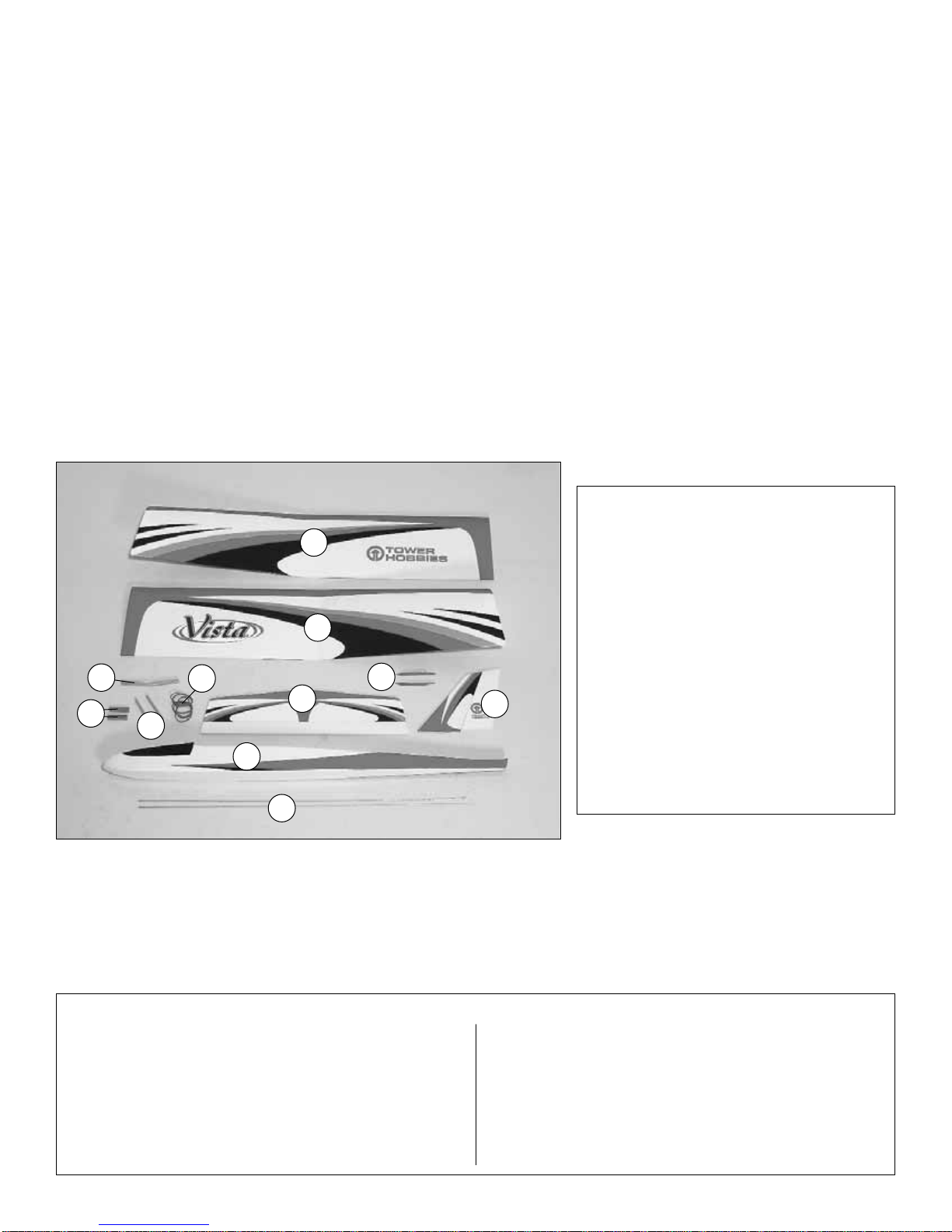
Kit Contents
1. Left Wing Panel
2. Right Wing Panel
3. Wing Joiner
4. Servo Rails (2)
5. Wing Dowels (2)
6. Rubber Bands (6)
7. Horizontal Stabilizer (Stab) w/Elevator
8. R&L Vertical Stabilizer Braces
9. Vertical Stabilizer (Fin) w/Rudder
10. Fuselage
11. Pushrods (2)
Kit Contents (not photographed)
Nylon Control Horns w/Mounting Plates (2)
Nylon Clevises (2)
Nylon 90° Pushrod Connectors (2)
Nylon Tail Skid
Tow Hook
Washer
2 x 10mm Screws (4)
Silicone Clevis Retainers (2)
3mm Nut
1/8" x 3/8" x 8" [3 x 10 x 200mm] Balsa Stick
1
2
5
9
8
11
7
10
3
4
6
Page 5
ASSEMBLY
Join the Wings
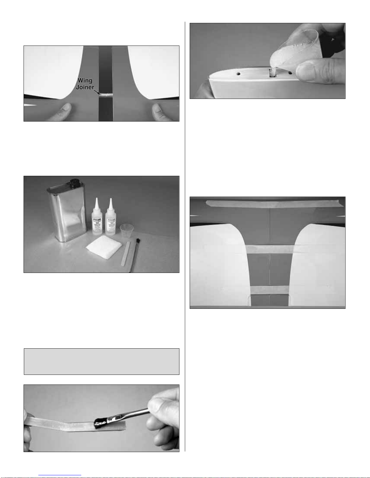
❍
1. Without using any glue, test fit both wing halves
together with the wing joiner. Make sure the halves fit
together well and there is no gap. If there is a problem with
the fit, look for obstructions such as glue bumps or wood
slivers inside the wings where the joiners fit. Make any
adjustments necessary to get a good fit.
❍
2. Place a sheet of wax paper on your workbench and
gather all the items required for joining the wings: 30-minute
epoxy, a mixing cup, an epoxy mixing stick, an epoxy brush,
paper towels and denatured alcohol for epoxy clean up.
Hint: To cut down on waste, cut the paper towels into
several small squares as shown in the photo.
Caution: Do not use 5-minute epoxy for joining the wing
halves. It will not provide enough working time.
❍
3. Separate the wings and take out the joiner. Mix up
approximately 1/2 oz. [15cc] of 30-minute epoxy. Use an
epoxy brush to coat both ends of the wing and one half of
the joiner all the way around. Pour a generous amount of
epoxy into one of the wings where the joiner goes, and then
slowly insert the epoxy-coated half of the joiner. Wipe away
excess epoxy as it is forced out of the wing. Note: There
must be no “empty space” inside the wing where the joiner
fits–the cavity must be filled with epoxy. If no epoxy “oozes”
out when you installed the joiner, remove the joiner and add
more epoxy. Then reinstall the joiner. Proceed rapidly to the
next step.
❍
4. Coat the protruding end of the joiner all the way around
with epoxy and pour epoxy into the other wing. Join the wing
to the other joiner/wing assembly, slowly pressing the two
halves together. Allow excess epoxy to drip out as you go.
When the wings come together, wipe away excess epoxy
that is squeezed out. Then use several strips of masking
tape on both the top and bottom of the wing to tightly hold
the two halves together. If epoxy continues to work out of the
wing under the tape, remove one strip at a time and wipe off
the epoxy. Then replace the tape with another strip. Do not
disturb the wing until the epoxy has hardened.
❍
5. After the epoxy has fully hardened, slowly and carefully pull
away the masking tape. If any of the covering loosened, iron it
back down with a covering iron on medium heat. Use a covering
sock over the iron to protect the Tower Vista’s finish.
Read steps 3 and 4 all the way through before
proceeding. It is important to use the proper technique for
joining the wing halves to ensure a strong wing.
5
Page 6

ASSEMBLE THE FUSELAGE
Join the Stabilizer
❍
1. If you haven’t done so already, remove the protective
foam piece from the aft end of the fuselage where the
stabilizer goes. Cut the covering at the opening from the
rudder pushrod tube and from the slot in the back of the
fuselage for the elevator pushrod.
❍
2. Cut off any covering that has been wrapped around the
side of the fuselage over the top of the stab saddle where
the stabilizer goes.
❍
3. Use a sharp hobby knife to cut the covering from the
bottom only of the horizontal stabilizer (stab) over the half-
circle notch in the trailing edge. Also cut the covering from
both sides of the stab over the half-circle notch in the
leading edge.
❍
4. Place the stab on the fuselage, keying the notches in
the stab into the pegs on the fuselage. Use a fine-point, felttip pen to mark the outline of the fuselage onto the stab.
❍
5. Take the stab off the fuselage and follow the proceeding
Expert Tip
or use a sharp hobby knife with a straightedge to
cut along the lines. If using a hobby knife to cut the covering,
take great care not to cut into the wood. Cutting into the wood
will weaken the structure which could cause it to fail in flight.
6
Page 7

❍
6. Peel the covering from the bottom of the stabilizer.
❍
7. Reposition the stabilizer onto the fuselage. Resting the
fuselage on your workbench, place a weight on top of the
stab to hold it down. View the fuselage from the rear. If the
stab is parallel with the workbench, proceed to the next step.
If the stab is not parallel with the workbench, remove the
stab and use medium-grit sandpaper to sand down the “high
side” of the stab saddle where the stab rests until you can
get the stab level.
❍
8. Use 30-minute epoxy to glue the stab into position–be
certain to coat both the bottom of the stab and the fuselage
with epoxy. Use weight or T-pins to hold the stab in position
until the epoxy hardens.
Join the Fin
❍
1. Taking accurate measurements, use a fine-point, felttip pen to mark the center of the fuselage in the two
locations shown.
❍
2. Using the marks to align a straightedge, mark a
centerline down the top of the fuselage and onto the stab as
shown—this will be used to align the fin.
❍
3. Place the fin on the fuselage, accurately aligning it over
the centerline. Without using any glue, place the tri-stock fin
braces on both sides of the fin. The same as was done with
the bottom of the stab, use a fine-point, felt-tip pen to mark the
outline of the fin braces onto the fuselage top and the fin.
How to cut covering from balsa.
Rather than using a hobby knife which could
inadvertently cut into the balsa, use a heated soldering
iron. Move the iron at a pace that will just melt the
covering without burning into the wood–the hotter the
soldering iron, the faster you will have to move it. A sharp
tip isn’t necessary, but a fine-point does work best.
7
Page 8

❍
4. Working carefully without cutting into the balsa, use
your heated soldering iron or a sharp hobby knife to cut the
covering from the sides of the fin and the top of the
fuselage. Make sure you cut just inside the
lines–approximately 1/32" [.5mm]–so that none of the balsa
will be exposed when all the parts are joined.
❍
5. Use one of your paper towel squares moistened with
denatured alcohol to wipe away the ink lines.
❍
6. Use 30-minute epoxy to glue the fin to the fuselage
with T-pins to hold the fin in position. Before the epoxy
hardens use a builder’s square to check to see if the fin is
perpendicular to the stab. If necessary, use tape to pull the
fin over to one side or the other to get the fin vertical. Allow
the epoxy to harden before proceeding.
❍
7. Take out the T-pins. Glue the tri stock braces into position
with 30-minute epoxy using T-pins to hold them in place.
❍
8. While you have some epoxy mixed, glue in both
wing dowels.
Hook Up the Controls
❍
1. Cut one of the wire pushrods to a length of 27"
[685mm] by cutting off the non-threaded end. Cut the other
pushrod to a length of 29-3/4" [685mm].
❍
2. Thread one of the pushrods halfway into one of the
clevises–this should take about fifteen full turns. Cut the
mounting plate off one of the control horns. Slide a silicone
retainer over the clevis, then connect the clevis to the third
hole out from the bottom of the horn. Prepare the other
pushrod the same way.
❍
3. Slide the longer pushrod into the elevator guide tube in
the fuselage. Mark, then drill 3/32" [2.4mm] holes through
the elevator for the two elevator horn mounting screws.
Mount the elevator horn with two 2 x 10mm screws and the
plastic mounting plate.
8
Page 9

Note: If the silicone retainer on the clevis rubs against the inside
of the fuselage sides, use a hobby knife to trim the inside of the
fuselage as necessary for free, smooth movement.
❍
4. Install the rudder pushrod and mount the control horn
the same way.
❍
5. Without using any glue, install both hardwood servo
rails into the slots. Glue the forward rail into the fuselage as
far forward as it will go.
Refer to this photo for the following four steps.
❍
6. Position the servos on the rails and slide them forward
against the forward rail. Note the position of the splined
output shaft on the servos (the elevator servo is facing aft
and the rudder servo is facing forward). Space the rail
approximately 3/32" [3mm] aft of the servos, and then
securely glue the rail into position.
❍
7. Place the servo arms on the servos–if your servos
came with a selection of servo arms, select ones that will
not interfere with the other servo or the fuselage sides. For
Futaba®and Tower servos, use the six-arm servo arms and
cut off the unused arms.
❍
8. Position the left servo all the way over to the left side
of the fuselage, then drill 1/16" [1.6mm] holes through the
rails for the servo mounting screws. Mount the servo with
the screws that came with it.
❍
9. Move the rudder servo as far over to the right as it will
go without the arm contacting the right fuselage side.
Drill 1/16" [1.6mm] holes through the rails and mount the
rudder servo with the screws that came with the servo.
❍
10. Center the servo arms as shown holding the elevator
pushrod so the elevator is centered. Mark the pushrod where it
crosses the holes in the elevator servo arm.
❍
11. Use pliers to make a 90° bend in the pushrod at the
mark you made.
❍
12. Take the servo arm off the servo. Enlarge the holes in
the servo arms with a servo horn drill (HCAR0698), a 5/64"
[2mm] drill bit or a hobby knife. Connect the pushrod to the
outer hole in the elevator servo using a 90° pushrod
connector. Cut the pushrod 1/16" [1.6mm] from the connector.
Then replace the servo arm on the servo.
❍
13. Connect the rudder pushrod to the rudder servo the
same way.
9
Page 10

Install the Receiver & Battery
Refer to this photo while installing the receiver and battery .
❍
1. Noting how the rubber band on the canopy hatch is
attached to the tab on the former (so you will know how to
reattach it later), unhook the rubber band and temporarily
remove the canopy hatch and set it aside.
❍
2. Connect the servos and on/off switch to the
receiver–on most four-channel airplanes, the rudder is
operated by the left stick on the transmitter. However, on
two-channel planes such as this (that do not have ailerons),
the rudder is controlled by the right stick. Connect the
rudder servo to the channel in the receiver that will allow the
rudder to be controlled by the right stick–for Futaba
receivers that is channel 1.
❍
3. Wrap the receiver and receiver battery in 1/4" [6mm]
R/C foam rubber. Use tape or small rubber bands to hold the
foam rubber in place.
❍
4. Place the receiver in the fuselage where shown.
Connect the receiver battery to the on/off switch, and then
place it in the fuselage ahead of the receiver.
❍
5. Cut the 1/8" x 3/8" x 8" [3 x 10 x 200mm] balsa stick to
the lengths required to fit between the fuselage sides where
shown. Then glue the sticks in place, holding the receiver
and battery in position.
❍
6. Use the mounting plate from your receiver on/off switch
as a template to cut and drill holes in the fuselage side. Then
mount the switch.
❍
7. Guide the receiver antenna past the servos, then through
one of the cut off servo arms as shown to make a “strain relief”
that keeps tension off the solder joint inside the receiver.
❍
8. Drill a 1/16" [1.6mm] hole through the side of the
fuselage where shown. Then guide the antenna through the
hole. Use clear tape to hold the receiver antenna to the
outside of the fuselage.
GET THE MODEL READY TO FLY
Final Assembly
❍
1. Use a piece of wire or a small, wood dowel to reattach
the rubber band and reinstall the canopy hatch.
❍
2. Thread the 3mm nut onto the tow hook and slip on the
3mm washer with a drop of thread-lock or CA. Thread the
hook into one of the three holes in the bottom of the
fuselage. Use a 5.5mm wrench or needle-nose pliers to
10
Page 11

tighten the nut and secure the hook. The forward hole is
recommended for starting out as it will provide mild
launches for first flights. Later, the hook may be moved aft
for more aggressive, higher launches.
❍
3. Cut off two of the barbs from the pegs on the tail skid.
Drill 1/8" [3.2mm] holes through the bottom of the fuselage
for the prongs. Then glue the tail skid into position.
Check the Control Directions
❍
1. Turn on the transmitter and receiver and center the
trims. If necessary, remove the servo arms from the servos
and reposition them so they are centered. Don’t forget to
install the screws that hold on the servo arms.
❍
2. With the transmitter and receiver still on, check all the
control surfaces to see if they are centered. If necessary,
screw the clevises on the pushrods in or out to center the
control surfaces.
❍
3. Make certain that the elevator and rudder respond in the
correct direction as shown in the diagram. If necessary, use the
servo reversing function in the transmitter to reverse the servos
so they respond in the right direction. Be certain the elevator and
rudder have remained centered. Adjust if necessary.
Set the Control Throws
Use a ruler to measure and set the control throw of the
elevator and rudder as indicated in the chart that follows. If
your radio does not have dual rates, we recommend setting
the throws at the low rate setting.
Note: The rudder throw is measured at the bottom of
the rudder.
Balance the Model (C.G.)
At this stage the model should be in ready-to-fly condition
with all of the systems in place including the servos, switch,
battery and receiver.
More than any other factor, the C.G. (balance point) can
have the greatest effect on how a model flies, and may
determine whether or not your first flight will be
successful. If you value this model and wish to enjoy it for
many flights, DO NOT OVERLOOK THIS IMPORTANT
PROCEDURE. A model that is not properly balanced will
be unstable and possibly unflyable.
IMPORTANT: The Tower Vista 2m sailplane has been
extensively flown and tested to arrive at the throws at
which it flies best. Flying your model at these throws will
provide you with the greatest chance for successful first
flights. If, after you have become accustomed to the way
the Tower Vista 2m sailplane flies, you would like to
change the throws to suit your taste that is fine. However,
too much control throw could make the model difficult to
control, so remember, “more is not always better.”
These are the recommended control surface throws:
High Rate Low Rate
ELEVATOR: 5/8" [16mm] up 3/8" [10mm] up
5/8" [16mm] down 3/8" [10mm] down
RUDDER: 1-1/2" [38mm] right 5/8" [16mm] right
1-1/2" [38mm] left 5/8" [16mm] left
11
4-CHANNEL
TRANSMITTER
4-CHANNEL
TRANSMITTER
Page 12

❍
1. If you will be using a Great Planes C.G. Machine™to
balance your model, set the rulers to 4" [100mm]. Place the
plane on the machine. If you will not be using the C.G.
Machine, use a felt-tip pen or narrow (1/8" [3mm] or less)
tape to mark a line, noting the C.G. on the bottom of the
wing 4" [100mm] back from the leading edge.
❍
2. Attach the wing to the fuselage with a couple of rubber
bands. The model must be totally ready to fly with all of the
components installed. Place the model on the Great Planes
CG Machine or lift it at the balance point you marked. You
should be able to feel the tape lines with your fingers.
❍
3. When supporting the model at the C.G. it is likely that
the tail will drop, indicating that it is “tail heavy” and weight
must be added to the nose. If the nose drops however, the
model is “nose heavy” and weight must be added to the tail.
Use Great Planes Self-Adhesive Lead Weights to balance
the model. Nose weight can be attached inside the fuselage
to the former as shown. Approximately 2 oz. [60g] of ballast
will be required for most models.There is also a cavity in the
balsa nose block for lead or steel shot (not included). If you
prefer to install lead or steel shot in the cavity, determine the
amount required, mix with epoxy, then pour in. Weight
installed in this manner will be permanent.
❍
4. IMPORTANT: If you found it necessary to add any
weight, recheck the C.G. after the weight has been installed.
PREFLIGHT
Identify Y our Model
No matter if you fly at an AMA sanctioned R/C club site or if you
fly somewhere on your own, you should always have your
name, address, telephone number and AMA number on or
inside your model. It is required at all AMA R/C club flying sites
and AMA sanctioned flying events. Fill out the identification tag
on page 15 and place it on or inside your model.
Charge the Batteries
Follow the battery charging instructions that came with your
radio control system to charge the batteries. You should
always charge your transmitter and receiver batteries the
night before you go flying, and at other times as
recommended by the radio manufacturer.
Range Check
Ground check the operational range of your radio before the
first flight of the day. With the transmitter antenna collapsed
and the receiver and transmitter on, you should be able to walk
at least 100 feet away from the model and still have control.
Have an assistant stand by your model and, while you work
CAUTION: Unless the instructions that came with your
radio system state differently, the initial charge on new
transmitter and receiver batteries should be done for 15
hours using the slow-charger that came with the radio
system. This will “condition” the batteries so that the next
charge may be done using the fast-charger of your choice.
If the initial charge is done with a fast-charger, the batteries
may not reach their full capacity and you may be flying with
batteries that are only partially charged.
This is where your model should balance for the first
flights. Later, you may wish to experiment by shifting the
C.G. up to 1/2" [13mm] forward or 1/2" [13mm] back to
change the flying characteristics. Moving the C.G.
forward may improve wind penetration and stability, but
the model will then fly and land a little faster. Moving the
C.G. aft makes the model lighter and more responsive to
thermals, but could also cause it to become too difficult to
control. In any case, start at the recommended balance
point and do not at any time balance the model outside
the specified range.
12
Page 13

the controls, tell you what the control surfaces are doing. If the
control surfaces do not respond correctly, do not fly! Find and
correct the problem first. Look for loose servo connections or
broken wires, corroded wires on old servo connectors, poor
solder joints in your battery pack or a defective cell, or a
damaged receiver crystal from a previous crash.
AMA SAFETY CODE (excerpts)
Read and abide by the following excerpts from the Academy
of Model Aeronautics Safety Code. For the complete Safety
Code refer to
Model Aviation
magazine, the AMA web site
or the Code that came with your AMA license.
General
1) I will not fly my model aircraft in sanctioned events, air
shows, or model flying demonstrations until it has been
proven to be airworthy by having been previously,
successfully flight tested.
2) I will not fly my model aircraft higher than approximately
400 feet within 3 miles of an airport without notifying the
airport operator. I will give right-of-way and avoid flying in
the proximity of full-scale aircraft. Where necessary, an
observer shall be utilized to supervise flying to avoid having
models fly in the proximity of full-scale aircraft.
3) Where established, I will abide by the safety rules for the
flying site I use, and I will not willfully and deliberately fly my
models in a careless, reckless and/or dangerous manner.
5) I will not fly my model unless it is identified with my name
and address or AMA number, on or in the model. Note: This
does not apply to models while being flown indoors.
7) I will not operate models with pyrotechnics (any device
that explodes, burns, or propels a projectile of any kind).
Radio Control
1) I will have completed a successful radio equipment ground
check before the first flight of a new or repaired model.
2) I will not fly my model aircraft in the presence of
spectators until I become a qualified flier, unless assisted by
an experienced helper.
3) At all flying sites a straight or curved line(s) must be
established in front of which all flying takes place with the
other side for spectators. Only personnel involved with flying
the aircraft are allowed at or in the front of the flight line.
Intentional flying behind the flight line is prohibited.
4) I will operate my model using only radio control frequencies
currently allowed by the Federal Communications Commission.
5) I will not knowingly operate my model within three
miles of any pre-existing flying site except in
accordance with the frequency sharing agreement
listed [in the complete AMA Safety Code].
9) Under no circumstances may a pilot or other person
touch a powered model in flight; nor should any part of the
model, other than the landing gear, intentionally touch
the ground except while landing.
CHECK LIST
❍
1. Check the C.G. according to the measurements
provided in the manual.
❍
2. Be certain the battery and receiver are
securely mounted.
❍
3. Extend your receiver antenna and make sure it has a
strain relief inside the fuselage to keep tension off the
solder joint inside the receiver.
❍
4. Make sure the tow hook is securely tightened.
❍
5. Confirm that all controls operate in the correct direction
and the throws are set up according to the manual.
❍
6. Make sure all the servo arms are mounted to the
servos with the screws included with your radio.
❍
7. Place your name, address, AMA number and
telephone number on or inside your model.
❍
8. Cycle your receiver battery pack (if necessary) and
make sure it is fully charged.
❍
9. If you wish to photograph your model, do so before
your first flight.
❍
10. Range check your radio when you get to the flying field.
FLYING
Mount the Wing
Mount the wing to the fuselage with the six #64 rubber
bands that came with the model. Install them one at a time,
crisscrossing the last two. Never use torn, cracked or oily
rubber bands.
If the rubber bands you will be using are different from those
recommended, consult an experienced modeler to make
certain they are strong enough, and that you have used
enough of them. If uncertain, force the front of the wing off
of the wing saddle. There should be considerable
resistance! If the wing can be forced from the fuselage
without having to strain your hands, then there are probably
not enough rubber bands. If launching the Tower Vista 2m
sailplane with launch systems stronger than those
recommended in this manual, additional #64 rubber bands
will be necessary.
IMPORTANT!!! Flying a model with too few rubber bands
can be dangerous. The wing could actually detach from the
fuselage resulting in a crash. If the model exhibits any
tendencies that indicate there are not enough rubber bands,
immediately land and closely inspect the model for damage.
If no damage is found, add more rubber bands.
Use this Check List to make sure you haven’t forgotten
anything during the last few seconds of preparation.
13
Page 14

Trim Flights
Before the first flight of the day, don’t forget to do a range
check and make sure the elevator and rudder are
functioning properly and respond in the correct direction.
Turn on the transmitter first and then the receiver. Hold the
Tower Vista 2m sailplane under the wing with the nose
pointed slightly down and directly into the wind. Launch the
model with the wings level and the nose pointing at a spot
on the ground about 50 feet [15m] in front of you. If the
sailplane is launched with the nose up or launched too hard
it will climb a few feet, stall and fall nose first straight down.
Launch the plane with a gentle push forward. Adjust the
trims on the transmitter so the plane flies straight ahead in
a smooth glide path.
First Flights
Find a BIG, OPEN field for your first flights. The bigger the
better, as you won’t have to worry about where to land. Ground
based objects (trees, poles, buildings,
etc.) can cause the
beginner to become easily
disoriented. Try to find an
experienced pilot to help you with your first flights.
Although the
Tower Vista 2m sailplane is very easy to fly, an
experienced
pilot can save you a lot of time and possible aggravation by
helping you get your model in the air smoothly.
Follow the directions that came with your hi-start and lay it
out directly into the wind. Place the stake at the far upwind
edge of the flying field so the parachute will blow back onto
the flying field.
Turn on your transmitter and then your receiver and hook
the parachute onto your plane’s tow hook. Pull the plane
back until there is approximately 8 lbs. [3.5kg] of tension on
the high start. More tension can be used after you get
acquainted with the launching procedure.
Hold the plane above your head with the wings level and the
nose pointed slightly up and directly into the wind. Give the
plane a strong push forward to get it flying and it will climb
up like a kite. You should not have to touch the elevator
during the launch but use the rudder stick to keep it going
straight up.
Note: You need to remember that your radio control
responds as if you were sitting in the cockpit. When you
push the transmitter stick to the right, the rudder moves to
the plane’s right! This means that when the plane is flying
towards you, it may seem like the rudder controls are
reversed (when you give “right” rudder the plane turns to
your left–which is the plane’s “right”). It is sometimes easier
to learn to fly the plane if you always face your body in the
direction the plane is flying and look over your shoulder to
watch the model.
Use these first flights to get the “feel” of the controls and the
Tower Vista 2m sailplane’s flying characteristics. Try to keep
the plane upwind and just perform some gentle S-turns
(always turning into the wind) until it is time to set up for
landing. When it is time to land, just continue performing the
gentle S-turns upwind and let the plane glide onto the
ground. Don’t worry about where the plane lands – just use
caution to avoid hitting anything. Always try to launch and
land into the wind.
No matter how much – or how little – previous R/C flying
experience you have, you’ll thoroughly enjoy piloting the
Tower Vista 2m sailplane. Its built-in stability keeps you calm
and confident at the controls. And when your “beginner”
days are behind you, the Tower Vista 2m sailplane’s
versatile performance can even help you earn impressive
contest wins. It will be one of your favorites for many years
to come.
Happy flying!
14
Page 15

OTHER ITEMS AVAILABLE FROM
TOWER HOBBIES
Tower Hobbies 4-TH 4-Channel FM Radio
The 4-TH is as affordable as it is perfect for first-time and
sport fliers. Narrow-band FM technology and a dualconversion receiver ensure that reception is as interferenceresistant as the transmission. Rounded transmitter contours
take it easy on the hands, while length and tension
adjustments tailor all-important stick “feel” to your own
needs. Servo reversing adds installation ease to the list of
conveniences, which also includes easy-to-reach trims,
600mAh Tx and Rx NiCds, a dual-output charger, Futaba
J-compatible connectors – and a trainer system to make it
easy to teach flying skills or learn new ones. Requires
servos. 1-year warranty. 72MHz. TOWJ41**
DYNAFLITE™HI-STARTS
DYFP8301 (Standard)
DYFP8302 (Heavy-Duty)
A Dynaflite Hi-Start and 800' of clear launch area are all you
need to send your sailplane rocketing up to 500' in the air!
Easy to lay out and retrieve, Hi-Starts include everything
required for sailplane launches: 100' of UV-stabilized
surgical tubing, injection-molded reel, parachute, steel stake
and tow ring, and nylon tow line. Standard Hi-Start with 1/8"
diameter tubing offers strong, steady power for 2-meter
sailplanes. Heavy-Duty Hi-Start with 3/16" diameter tubing
provides the launch power needed for sailplanes spanning
100" or more.
Great Planes C.G. Precision Aircraft Balancer
™
Accurate balancing makes trainers more stable, low-wings
more agile, and pylon planes move at maximum speed. The
innovative C.G. Machine helps you achieve optimum balance
easily, without measuring or marking–and without the errors
that fingertip balancing can cause. You’ll quickly pinpoint your
plane’s exact center of gravity. Then you’ll know at a glance
whether weight should be added, removed or relocated. The
C.G. Machine works with kits and ARF models of any size and
wingspan. Its slanted wire balancing posts support models
weighing up to 40 pounds. GPMR2400
Cut out or copy the identification tag and put it on or inside
your model.
15
Page 16

BUILDING NOTES
Kit Purchased Date: _______________________
Where Purchased:_________________________
Date Construction Started: __________________
Date Construction Finished: _________________
Finished Weight: __________________________
Date of First Flight: ________________________
FLIGHT LOG
 Loading...