

Page 1
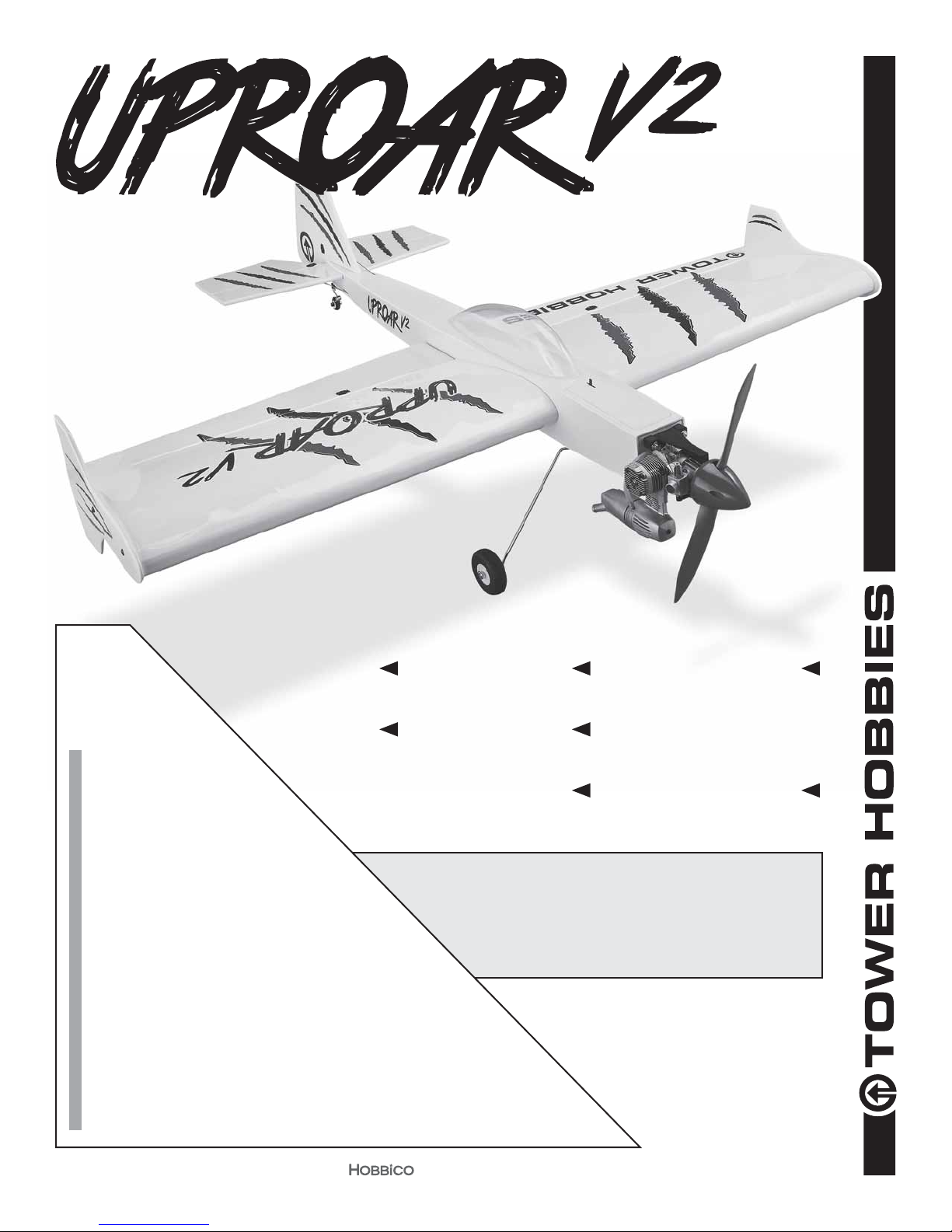
.46 EP ARF
®
Tower
Hobbies®
guarantees
this kit to be
free from defects
in both material and
workmanship at the
WARR ANT Y
date of purchase. This
warranty does not cover any
component parts damaged by
use or modication. In no case shall
Tower Hobbies’ liability exceed the
original cost of the purchased kit. Further,
Tower Hobbies reserves the right to change
or modify this warranty without notice.
In that Tower Hobbies has no control over the nal
assembly or material used for nal assembly, no
liability shall be assumed nor accepted for any damage
resulting from the use by the user of the nal user-assembled
product. By the act of using the user-assembled product, the
user accepts all resulting liability.
If the buyer is not prepared to accept the liability associated with the
use of this product, the buyer is advised to return this kit immediately in
new and unused condition to the place of purchase.
To make a warranty claim send the defective part or item to Hobby Services at
the address below:
Hobby Services • 3002 N. Apollo Dr. Suite 1 • Champaign IL 61822 • USA
Include a letter stating your name, return shipping address, as much contact information as
possible (daytime telephone number, fax number, e-mail address), a detailed description of
the problem and a photocopy of the purchase receipt. Upon receipt of the package the problem
will be evaluated as quickly as possible.
WINGSPAN
47.6 in [ 1210mm]
48.1 in [ 1222mm]
INSTRUCTION MANUAL
WING AREA
630.8 in2 [40.7 dm2]
LENGTH
4.6– 4.7lbs [2064–2133g]
WING LOADING
16 – 17 oz / f t2 [51–52 g/dm2]
READ THROUGH THIS MANUAL
WEIGHT
BEFORE STARTING CONSTRUCTION.
IT CONTAINS IMPORTANT INSTRUCTIONS
AND WARNINGS CONCERNING THE
ASSEMBLY AND USE OF THIS MODEL.
POWER
Glow: .46 cu. in. 2-stroke
Electric: 1.70in [42mm] diameter,
925W, Hitec Energy Sport 80 ESC
RADIO
4 – 5 channels
TOWER HOBBIES
Champaign, Illinois
(217) 398-8970 ext. 6
airsupport@hobbico.com
®
®
© 2017 Tower Hobbies.
A subsidiary of Hobbico, Inc.
TOWA2040 v1.1
Page 2

TABLE OF CONTENTS
INTRODUCTION . . . . . . . . . . . . . . . . . . . . . . . . . . . . . . . . 2
ADDITIONAL ITEMS REQUIRED . . . . . . . . . . . . . . . . . . . 2
Radio/Servos . . . . . . . . . . . . . . . . . . . . . . . . . . . . . . . . 2
Glow Engine. . . . . . . . . . . . . . . . . . . . . . . . . . . . . . . . . 2
Brushless Electric Motor . . . . . . . . . . . . . . . . . . . . . . . 2
LiPo Battery Charger . . . . . . . . . . . . . . . . . . . . . . . . . . 3
Adhesives, Hardware & Other Accessories . . . . . . . . . 3
KIT INSPECTION. . . . . . . . . . . . . . . . . . . . . . . . . . . . . . . . 3
PARTS LIST . . . . . . . . . . . . . . . . . . . . . . . . . . . . . . . . . . . . 3
KIT CONTENTS. . . . . . . . . . . . . . . . . . . . . . . . . . . . . . . . . 4
PREPARATION . . . . . . . . . . . . . . . . . . . . . . . . . . . . . . . . . 4
ASSEMBLE THE WING. . . . . . . . . . . . . . . . . . . . . . . . . . . 5
Hinge the Ailerons . . . . . . . . . . . . . . . . . . . . . . . . . . . . 5
Hook Up the Ailerons. . . . . . . . . . . . . . . . . . . . . . . . . . 7
ASSEMBLE THE FUSELAGE . . . . . . . . . . . . . . . . . . . . . . 9
Prepare the Fuselage for the Stab & Fin . . . . . . . . . . . 9
Glue in the Horizontal & Vertical Stabilizers. . . . . . . . 12
Install the Receiver Battery . . . . . . . . . . . . . . . . . . . . 12
Attach the Elevator and Rudder. . . . . . . . . . . . . . . . . 13
Hook Up the Elevator and Rudder. . . . . . . . . . . . . . . 14
INSTALL THE POWER SYSTEM . . . . . . . . . . . . . . . . . . 15
Mount the Brushless Motor . . . . . . . . . . . . . . . . . . . . 15
INTRODUCTION
Congratulations and thank you for purchasing the Tower
Hobbies Uproar V2 ARF. The Uproar V2 is an exciting, updated
version of the original Uproar ARF. If you’re a casual sport
pilot, the Uproar V2 can be tamed simply by switching to
“normal” or low-rate control throws. Then it becomes a docile
every day sport yer.
For the latest technical updates or manual corrections, nd
the Uproar V2 ARF on the Tower Hobbies web site at www.
towerhobbies.com. If there is new technical information or
changes to this model, a “tech notice” box will appear on
the page.
ADDITIONAL ITEMS REQUIRED
Radio/Servos
Mount the Glow Engine . . . . . . . . . . . . . . . . . . . . . . . 16
Hook Up the Throttle . . . . . . . . . . . . . . . . . . . . . . . . . 18
Install the Fuel Tank . . . . . . . . . . . . . . . . . . . . . . . . . . 19
Final Radio Installation. . . . . . . . . . . . . . . . . . . . . . . . 20
FINAL ASSEMBLY. . . . . . . . . . . . . . . . . . . . . . . . . . . . . . 20
Mount the Main Landing Gear . . . . . . . . . . . . . . . . . . 20
Mount the Tail Gear . . . . . . . . . . . . . . . . . . . . . . . . . . 21
Mount the Canopy . . . . . . . . . . . . . . . . . . . . . . . . . . . 22
Attach the Side-Force Generators. . . . . . . . . . . . . . . 23
Apply the Decals . . . . . . . . . . . . . . . . . . . . . . . . . . . . 23
PREPARE THE MODEL FOR FLIGHT . . . . . . . . . . . . . . 24
Set the Control Throws . . . . . . . . . . . . . . . . . . . . . . . 24
Check the C.G. . . . . . . . . . . . . . . . . . . . . . . . . . . . . . 24
Balance the Model Laterally . . . . . . . . . . . . . . . . . . . 25
PREFLIGHT . . . . . . . . . . . . . . . . . . . . . . . . . . . . . . . . . . . 25
Engine/Motor Safety Precautions . . . . . . . . . . . . . . . 25
Battery Precautions . . . . . . . . . . . . . . . . . . . . . . . . . . 26
Range Check . . . . . . . . . . . . . . . . . . . . . . . . . . . . . . . 27
AMA SAFETY CODE (excerpts) . . . . . . . . . . . . . . . . . . . 27
General. . . . . . . . . . . . . . . . . . . . . . . . . . . . . . . . . . . . 27
Radio Control. . . . . . . . . . . . . . . . . . . . . . . . . . . . . . . 27
FLYING. . . . . . . . . . . . . . . . . . . . . . . . . . . . . . . . . . . . . . . 28
❍ (4) 6" [150mm] universal servo extensions (TACM2092)
are required for the ailerons (one on each servo and
one in each channel in the receiver).
If powering your Uproar V2 with a glow engine, a receiver
battery and on/off switch will also be required:
❍ Hobbico 2S 6.6V 1300mAh LiFe battery (HCAM6411)
❍ On-off receiver switch (TACM2000)
Glow Engine
The Uproar V2 is suited for a .46 2-stroke glow. The O.S.
Max .46AXII ABL (OSMG0548) is illustrated in this manual.
Other accessories for a glow engine
❍ 1/4" [6.4mm] R/C foam rubber (HCAQ1000)
❍ Fuel tubing (GPMQ4131)
❍ Suitable propeller for your engine
A minimum of 4-channels is required to y the Uproar V2 ARF.
The Tactic TTX650 transmitter is recommended because
of its simple, exible computer programming and multiple
model memory:
❍ Tactic TTX650 6-channel programmable radio
(TACJ2650)
❍ Tactic TR625 6-chanel receiver (TACJ0625)
❍ Tactic TSX25 mini digital high-speed 2 ball bearing
servos offer the most precision (TACM0225), but
Tactic analog servos are also suitable (TACM0220).
Four servos are required for a brushless setup and
ve servos for glow.
Brushless Electric Motor
The electric setup for the Uproar V2 is straightforward: a
Great Planes Electri y RimFire .32 on a 13 x 8 E prop with a
80A ESC powered by a 4S 3800mAh LiPo. A Hitec Energy
Sport 80 ESC is illustrated in the instruction manual. A 14 x
7E prop is also suitable.
❍ 42-50-800 RimFire .32 (GPMG4700)
❍ APC 13 x 8 thin E prop (APCQ3080)
❍ APC 14 x 7 thin E prop (APCQ4145)
❍ Hitec Energy Sport 80 ESC (HRCM9050)
❍ 3300mAh – 4000mAh 4S LiPo:
❍ FlightPower 4S 3800mAh 30C (FPWP3384)
❍ Venom Fly 4S 3600 mAh 30C (VNRA2516)
2
Page 3

LiPo Battery Charger
To charge a 4S 3800mAh LiPo at 1C a charger capable of
at least 65 Watts output power is required (4S x 4.2V/cell
= 16.8V x 3.8A = 63 Watts). The Triton EQ2 (GPMM3156) is
more than enough charger with 100W output AC and 120W
output DC.
Adhesives, Hardware &
Other Accessories
A covering iron with a cover sock may be required for
tightening and re bonding the covering to the model that may
have loosened between the time the plane was manufactured
and the time the model was removed from the box. The 21st
Century iron is preferred because of its long cord, contoured
shoe and precisely adjustable temperature range:
❍ Coverite 21st Century Sealing Iron (COVR2700)
❍ Coverite 21st Century Cover Sock (COVR2702)
KIT INSPECTION
Other than common hobby tools here is a list of the rest of
the items required:
❍ 30-minute epoxy (GPMR6043)
❍ Epoxy brushes (GPMR8060)
❍ Mixing cups (GPMR8056)
❍ Mixing sticks (GPMR8055)
❍ Threadlocker thread locking cement (GPMR6060)
❍ Thin CA (GPMR6001)
❍ Medium CA (GPMR6007)
❍ CA applicator tips (HCAR3780)
❍ CA accelerator (GPMR6035)
❍ GP Back/Back Hook 'n Loop Hold DownStrap 3/4x 24"
(GPMQ4476)
❍ GP Hook & Loop 1x6" (2) (GPMQ4480)
❍ GP Dead Center Hole Locator (GPMR8130)
❍ Zap Adhesives Formula 560 Canopy Glue 2 oz
(PAAR3300)
❍ Great Planes Standard Precision Prop Reamer
(GPMQ5006)
❍ Drills: 1/16" [1.6 mm], 3/32" [2.4 mm], 5/32" [4.0 mm],
13/64" (or 3/16") [5.0 mm], #49 (.073"), 1/8" [3.2mm]
Before starting to build, take an inventory of this kit to make
sure it is complete, and inspect the parts to make sure they
are of acceptable quality. If any parts are missing or are not of
acceptable quality, or if you need assistance with assembly,
contact Product Support. When reporting defective or
missing parts, use the part names exactly as they are written
in the Kit Contents list.
Tower Hobbies Product Support
3002 N Apollo Drive, Suite 1 Ph: (217) 398-8970, ext. 6
Champaign, IL 61822 Fax: (217) 398-7721
E-mail: airsupport@greatplanes.com
PARTS LIST
Order No. Description
TOWA4085
TOWA4086
TOWA4087
TOWA4088
TOWA4089
TOWA4090
TOWA4091
TOWA4092
TOWA4093
TOWA4094
TOWA4095
Wing Set
Fuselage
Horizontal Stabilizer
Vertical Stabilizer
Landing Gear Set
Wing Tip Plates
Canopy
Wing Joiner Tube
Tail Gear Set
Spinner
Decals
A Robart Super Stand II (ROBP1402) is also indispensable
for working on your Uproar V2.
3
Page 4
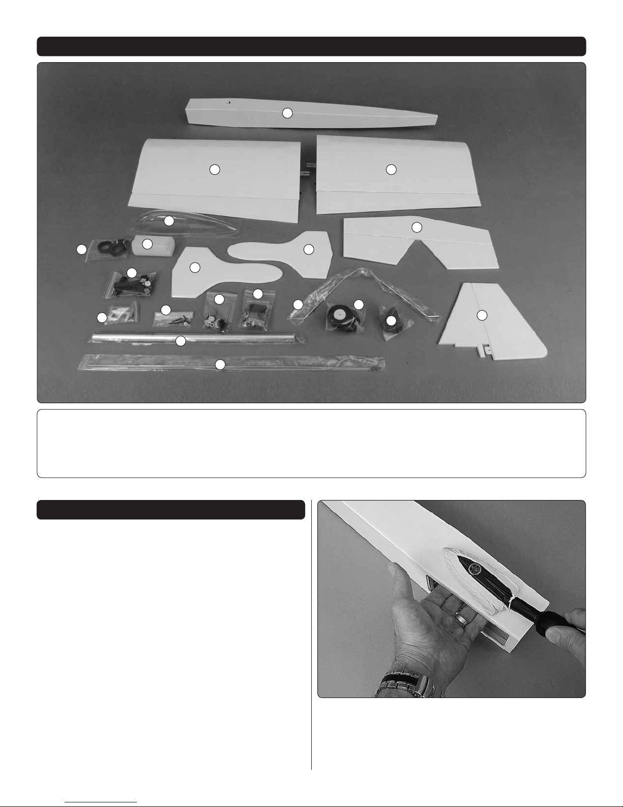
KIT CONTENTS
1
5
10
1. Fuselage
2. Wing
3. Wing
4. Canopy
5. Fuel Tank Hardware
2
4
6
7
11
8
12
18
19
13
6. Fuel Tank
7. Engine Mount Hardware
8. Wing Tip Plates
9. Horizontal Stabilizer
10. Control Horn Hardware
8
14
15
11. Nylon Hardware
12. Tail Gear Hardware
13. Fastener Hardware
14. Main Landing Gear Wire
15. Whe els
3
9
16
17
16. Spinner
17. Vertical Stabilizer
18. Wing Tube
19. Pushrods
PREPARATION
The covering on film-covered ARFs typically requires
retightening and rebonding to the structure underneath from
wrinkles that may appear between the time the covering was
applied and the time the kit arrived in your hands. The best
way to renew the covering job is with a covering iron with a
protective cover sock. We prefer a 21st Century cover iron
with a cover sock set to about 360 – 375F [180 – 190 C].
You may nd this is a little hotter than the temperature you
use on other coverings, but this material seems to require
more heat. The recommended temperature setting translates
to about 340F measured on the surface of the cover sock.
1. Glide the iron over unsupported lm, but where the
❏
lm is over wood apply pressure to bond the covering to the
wood. In some areas the wood will bow or bend inward, so
wherever possible, support the structure underneath with
your other hand. Adjust the heat setting as needed.
4
Page 5
2. Optional: Three or four pinholes can be punctured
❏
through the covering between each rib in the bottom of
the horizontal stabilizer, the elevators and ailerons, and in
one side of the vertical stabilizer and rudder. This will allow
heated, expanding air to escape while tightening covering.
These pinholes may appear obtrusive at rst, but when the
covering is heated they virtually disappear (plus, most of the
pinholes will be on the bottom). Heat the side of the covering
without the pinholes rst.
5. NOTE: The procedure for preparing the holes in wood
❏
for all wood screws is as follows:
A. Drill the hole with the drill speci ed in the step.
B. Install, then remove the screw to “set” the threads.
C. Add a drop or two of thin CA to harden the threads in
the hole.
D. Allow the CA to harden, then install the screw(s) with
whatever it is that is being mounted/installed/attached
(servos, landing gear, etc.).
ASSEMBLE THE WING
Hinge the Ailerons
The left wing is shown in the images, but both wings could
be assembled simultaneously.
3. Stack a few paper towels on top of each other and cut
❏
them into small squares. These small paper towel squares
come in handy for dabbing up excess CA or wiping up epoxy
when dampened with denatured alcohol.
4. NOTE: All machine-thread screws that thread into metal
❏
(hex nuts, blind nuts, wheel collars, etc.) should be lightly
wetted with threadlocker.
1. If not yet done, separate the aileron from the left wing
❏
and tighten the covering as previously described (the pinhole
technique works well for the ailerons).
5
Page 6

3. Rejoin the aileron to the wing with the hinges – as you
❏
close the hinge gap make sure the hinges remain centered
and make sure the tip of the aileron is even with the tip of
the wing.
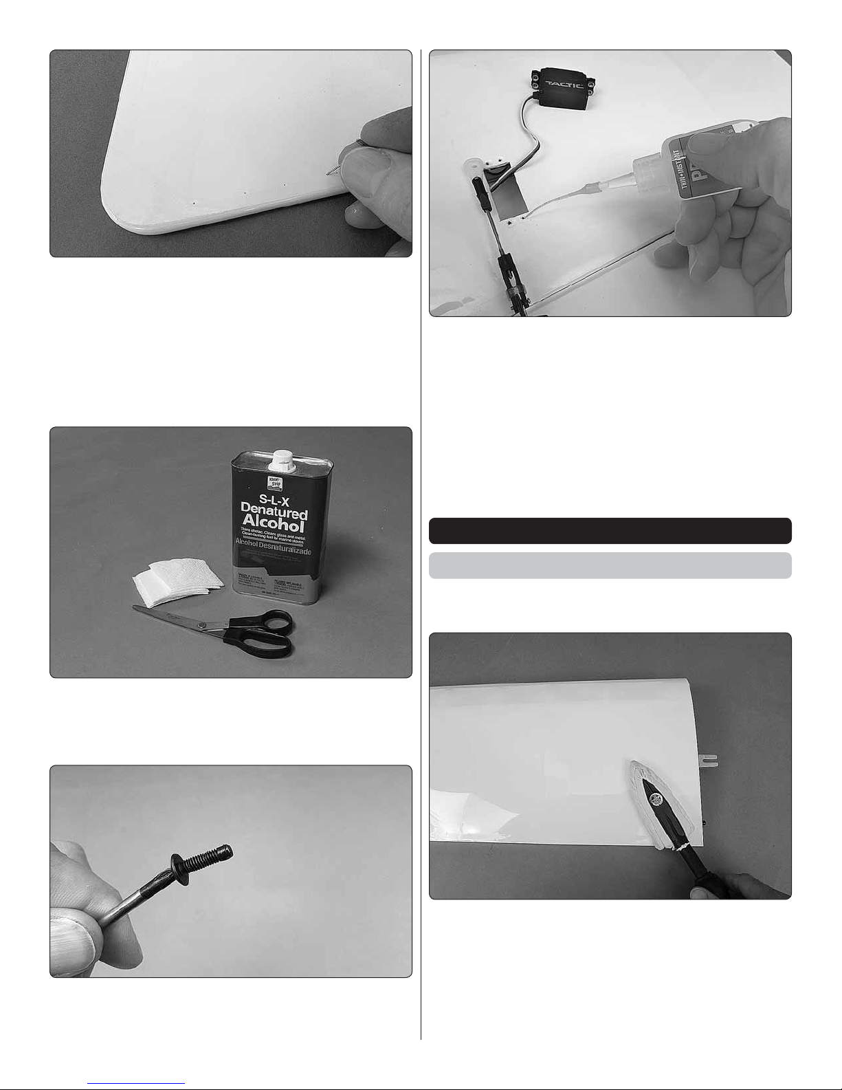
2. Cut the covering from the servo mount in the bottom of
❏
the wing – you may simply cut the covering along the edges,
or cut 1/8" [3mm] inside the edges, then seal down inside
with a trim iron.
4. Using a CA tip on a bottle of thin CA, apply ve or
❏
six drops to the top and bottom of each hinge – wait a few
seconds between drops for the CA to soak in. And keep
those small paper towel squares handy. They can be touched
edge-wise to the hinges to absorb excess CA before it wicks
along the hinge gap.
6
Page 7

5. After the CA has hardened ex the aileron up and down
2
1
3
4
90
❏
and pull hard to make sure the hinges are secure.
Continue with this wing, or go back to step 1 and hinge the
other aileron.
Hook Up the Ailerons
1. Attach a 6" [150mm] servo extension to the aileron servo.
❏
2. Use 1/2" [13mm] heat shrink tubing, tape or a dab of
❏
glue to secure the connections.
4. Connect the servo to your receiver with a battery so you
❏
can power the servo with the radio. Turn on the transmitter
and the receiver. Don’t forget to center the trims and subtrims in your transmitter programming. Fit a servo arm to
the servo that will be perpendicular to the servo as shown.
3. Fit the servo into the wing and drill 1/16" [1.6mm] holes
❏
for the servo mounting screws.
5. Cut off the unused servo arms and use a #49 (.073")
❏
drill to enlarge the holes in the remaining arm. (Even though
the pushrod wire measures .070" in diameter, a .073" drill
sizes the holes correctly because the plastic expands when
drilling the holes.) If you prefer, you may use a sanding drum
to trim the remainder of the cut-off arms (as was done for
the servo arm in the photo).
7
Page 8
6. Thread a 4" [100 mm] pushrod onto a clevis until a small
90-Degree
Pushrod
Connector
1/16" [1.6mm ]
❏
portion of the threads appear through the clevis as shown.
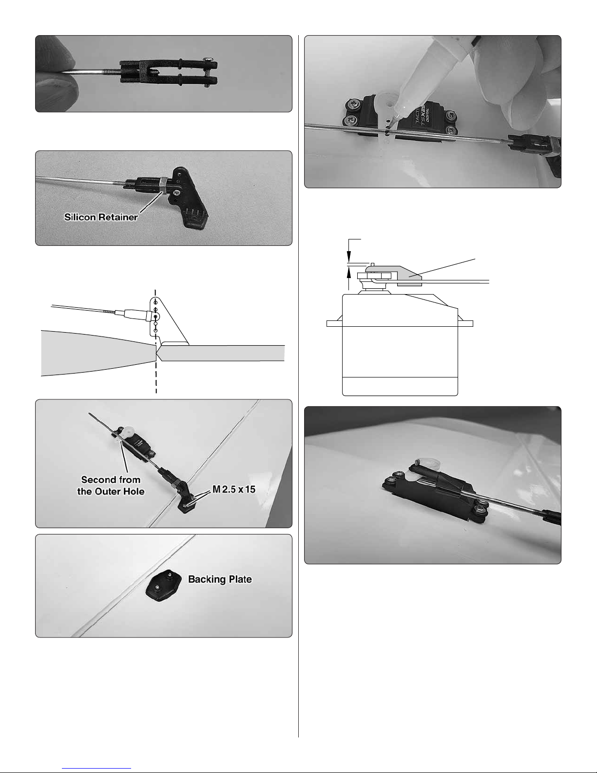
7. Connect the clevis to the middle hole in a control horn
❏
and secure with a silicone retainer.
9. With the aileron and servo arm centered, mark the
❏
pushrod where it crosses the hole in the servo arm.
8. Set the horn on the aileron so the pushrod will be in
❏
alignment with the second from the outer hole in the servo
arm (about 1/2" [13mm] out from center) and the clevis
holes in the horn will be centered over the leading edge of
the aileron. Using the holes in the horn as a guide, drill 3/32"
[ 2.4mm] holes through the aileron. Mount the horn to the
aileron with two M 2.5 x 15 Phillips wood screws and the horn
backing plate on the top of the aileron.
10. Make a 90-degree bend in the wire at the mark, connect
❏
the pushrod to the servo arm with a 90-degree pushrod
connector, and then cut off the excess wire.
11. As noted and pictured on page 5, remove the servo
❏
mounting screws and temporarily remove the servo from the
wing. Add a drop or two of thin CA to each screw hole, and
allow the CA to harden. Then, re-mount the servo.
12. Power the servo again with your radio. If necessary,
❏
remove the servo arm and thread or unthread the pushrod
from the clevis so the aileron will be centered when the servo
is centered. Reconnect the servo arm and fasten with the
servo arm screw that came with the servo.
8
Page 9

13. While the servo is still operational move the aileron
❏
up and down to check for smooth movement. Make any
adjustments necessary.
14. Prepare the other wing with the aileron servo the
❏
same way.
ASSEMBLE THE FUSELAGE
Prepare the Fuselage for the Stab & Fin
1. If you haven’t yet done so, address any covering issues
❏
on the fuselage and the tail parts as described on pages 4
and 5.
3. Also cut the covering from both sides over the wing
❏
tube holes, the alignment peg holes, the slots for the wing
retainers and for the aileron servo wires.
4. Cut the covering from the stab for the slot for the n
❏
post and from the bottom of the n where shown, being
cautious not to cut into the wood.
2. Cut the covering from the fuselage over the rudder
❏
pushrod exit and both elevator pushrod exits and from the
stab and n slots. Remove the temporary ller block from
the stab slot.
5. Slide both wings all the way onto the fuselage.
❏
9
Page 10

6. Test t the n and stab into the fuselage.
Trailing Edge of
Vertical Stabilizer
and End of
Fuselage Align
❏
the low side until the stab aligns with the wing – it shouldn’t
take much sanding and proceed in small increments. Once
the saddle is adjusted all that should be required is a small
amount of weight to hold down the high side.
8. Make certain the trailing edge of the vertical stabilizer
❏
aligns with the aft end of the fuselage. Otherwise the leading
edge of the rudder will not contact both parts, causing a
hinge gap.
9. The stab is pretty much locked-in and self-aligned
❏
with the fuselage, but there is a little free-play. If striving for
perfection, you could rotationally align the stab as follows:
7. View the model from behind to see if the stab is parallel
❏
with the wing. If it is not, sand the bottom of the stab saddle
on the high side of the stab and the top of the saddle on
A. Tie a loop around one end of an approximately 48”
[1200mm] non-elastic line. Fold a piece of masking tape
over the other end of the line. Mark a line on the tape.
B. Insert a pin into middle of the lip in the front of the fuselage
for the battery/fuel tank hatch. Loop the line over the pin.
10
Page 11

C. Hold the line with the tape to one corner of the stab.
Swing the line over to the corner on the other end of the
stab. Adjust the stab and slide the tape along the line until
the stab is centered and equalized.
10. Use a ne-point felt-tip pen to mark the base of the
❏
n onto the top of the fuselage.
11. Also mark the top and bottom of the fuselage onto the
❏
top and bottom of the stab.
12. Cut the covering from the top of the fuselage
❏
approximately 1/16" [1.6 mm] inside the n marks, being
cautious not to cut into the wood. Wipe away the ink lines
with a paper towel square dampened with denatured alcohol.
Then, remove the covering.
11
Page 12

13. Use a pin to puncture the covering on both sides of the
❏
stab just inside the lines you marked. Wipe away the ink lines
with a paper towel square dampened with denatured alcohol.
14. Finally, cut and remove a strip of covering from the top
❏
of the stab in alignment with the slot for the n post.
Glue in the Horizontal & Vertical Stabilizers
2. Mix up approximately 1/4 oz. of 30-minute epoxy. Apply
❏
epoxy to the top and bottom of the stab over the pinholes
aligned with the fuselage sides and to all other joining parts
of the fuselage and n.
3. Slide the stab into position, then add the n. If you’ve
❏
cut up balsa sticks, use them to wipe away most of the epoxy
followed by paper towel squares dampened with denatured
alcohol. Double-check alignment, place the weight on the
stab if used and allow the epoxy to harden.
4. After the epoxy has hardened remove the wing to
❏
proceed with assembly.
1. Gather your small paper towel squares and denatured
❏
alcohol for epoxy clean up. Small balsa sticks chopped up
from 1/16" [1.5 mm] balsa sheet are also handy for wiping
away most of the epoxy before using the paper towel squares.
Install the Receiver Battery
Skip this section if using a brushless motor and powering
the radio with a BEC or voltage regulator.
If installing the receiver battery in the location shown, this
must be done before the elevator and rudder pushrods have
been installed.
12
Page 13

1. Tape a layer of 1/4" RC foam around your receiver battery.
22-1/4" [570 mm]
❏
2. Some glow engine installations may require tail ballast,
❏
so it is desirable to mount the battery as far back as practically
possible which is why the location illustrated in this manual
was chosen. Install the battery, then hold it into position
with pieces cut from the 1/4" x1/2" x 4" [4 x10 x100 mm] balsa
stick as shown.
2. Applying the same procedures used for hinging the
❏
ailerons to the wings, join the elevators to the stab with the
hinges and permanently glue them in with thin CA. (If you’ve
poked pinholes in one side of the covering over the elevators
be sure to put those sides down.)
3. Make both elevator pushrods the same way you
❏
made the aileron pushrods; thread the clevises onto two
27-3/4" [705 mm] threaded one end pushrods, connect
the clevises with silicone retainers to the pushrods and
connect the clevises to the second-from-the-outer holes
in the control horns.
Attach the Elevator and Rudder
1. Cut the covering from the hinge slot in the end of the
❏
fuselage and test- t a CA hinge. If the hinge ts too tight,
enlarge the slot a little with a hobby knife or a small razor
saw blade.
4. Cut both pushrods to a length of 22-1/4" [570mm ] from
❏
the retainer screw to the end of the pushrod. Save one of
the pieces of wire you cut off.
5. Insert the pushrods into the elevator guide tubes in the
❏
fuselage and mount the horns to the elevators the same way
you did the aileron horns (drill 3/32" [2.4 mm] holes and use
M2.5 x 15 wood screws and the horn back plates on the top
of the elevators).
13
Page 14

6. Temporarily t the rudder to the n and fuselage with
❏
the hinges. Make the rudder pushrod the same way you
made the elevator pushrods, but don’t cut the wire. Slide
the pushrod into the fuselage, align the horn over the rudder
and mark the location of the screw holes.
Hook Up the Elevator and Rudder
1. Use the wire you saved from cutting the elevator
❏
pushrods to make a short pushrod with an L-bend for a
pushrod keeper as shown.
7. Remove the rudder and pushrod and leave the hinge
❏
nearest the horn in the rudder. Drill the holes through the
rudder for the screws – if the holes intersect the hinge, just
drill through the hinge.
8. Mount the rudder horn to the rudder (with the hinge
❏
in place), t the rudder back to the fuselage and glue in the
hinges with thin CA.
9. After the CA on all the hinges has hardened, ex the
❏
elevators and rudder up and down and pull on them to make
sure they are secure.
Refer to this image for the following three steps.
2. Place the elevator and rudder servos in the servo tray as
❏
shown, but do not mount the servos until instructed to do so.
3. Hook up the rudder and elevators with the same
❏
techniques used for the ailerons (centering the servos with
the radio on, nding the servo arm 90-degrees to each servo,
cutting off the unused arms, drilling out the holes with a #49
[.073"] drill and connecting the pushrods to the servos with
90-degree pushrod keepers). Install, but do not tighten the
set screws on the elevator pushrod link.
4. With all the pushrods connected, position the servos
❏
as shown with a little space between the rudder pushrod
and the elevator pushrod link so they will not interfere with
each other. Drill 1/16" [1.6 mm] holes through the servo tray
for mounting the servos. Mount the servos with the mounting
screws that came with them (don’t forget to harden the screw
holes with thin CA).
5. Adjust the clevis on the rudder pushrod so the rudder
❏
will be centered when the servo arm is centered.
14
Page 15

6. To adjust the elevator pushrods and tighten the elevator
❏
pushrod link, again with the radio on and the servo powered,
use a 1.5mm hex driver to rst tighten the middle set screw
locking the pushrod link to the pushrod. Using a straightedge
to hold one of the elevators at with the stab, tighten the
corresponding set screw in the link to lock the pushrod down.
Then, tighten the other set screw for the other pushrod the
same way.
7. Use the radio to move the elevators up and down
❏
observing the pushrods and the pushrod link to make
sure everything operates smoothly. Make any adjustments
necessary.
We’ll mount the on/off switch (if used) and receiver after the
engine/motor has been mounted.
INSTALL THE POWER SYSTEM
Mount the Brushless Motor
2. Drill 1/16" [1.6 mm] pilot holes through the “X” marks.
❏
Then, enlarge the holes with a 5/32" [4 mm] drill.
3. Cut and remove the piece from the firewall for the
❏
motor wires.
Skip to page 16 if installing a glow engine.
1. Push a pin or a small nail into the four “X” marks
❏
in the firewall that mark the location of the holes for the
mounting screws.
4. Mount the motor to the rewall with M3 x 15 button-
❏
head screws, M3 lock washers and at washers and M3
blind nuts in the back of the rewall.
15
Page 16

5. Apply a strip of the rougher, “hook” side of adhesive-
❏
back hook-and-loop material (not included) to the top of the
battery tray and apply a strip of the softer, “loop” side to the
bottom of your battery.
6. Cut a strip of hook-and-loop strap material (not included)
❏
to the correct length for a battery strap to hold your battery
to the battery tray.
8. Connect the ESC to the motor and place the ESC in
❏
the compartment aft of the battery compartment ahead of
the wing tube. Guide the signal wire from the ESC over the
wing tube into the radio compartment.
9. Test- t the battery in the battery compartment. Arrange
❏
the battery wires and make any adjustments necessary.
Skip ahead to Final Radio Installation on page 20.
7. Mount the battery tray in the battery compartment with
❏
four M3 x 10 button-head Phillips screws. Glue two 12 x 12
x 12mm balsa blocks to the back of the rewall to prevent
the battery from contacting the motor shaft that protrudes
out the back of the motor.
Mount the Glow Engine
For C.G. purposes, it is desirable to position the glow engine
as far aft on the engine mount as possible. This will minimize
(or possibly eliminate) any tail ballast that may be required.
1. Push a pin or a small nail into the four “+” marks
❏
in the rewall that mark the location of the holes for the
engine mount screws.
16
Page 17

2. Drill 1/16" [1.6mm] pilot holes through the “+” marks.
❏
Then, enlarge the holes with a 3/16" [5mm] drill.
3. Press M4 blind nuts into the holes in the back of
❏
the firewall.
5. Temporarily mount the engine mount with engine to
❏
the rewall with four M4 x 25 Phillips screws and M4 lock
washers and at washers. Use a Great Planes Dead-Center
hole locator to mark the rear engine mount screw holes onto
the engine mount.
6. Before removing the engine from the mount to drill the
❏
rear two mounting screw holes, sight-down a location on
the rewall for the throttle pushrod and guide tube. There
is already another “+” mark for the O.S. .46, but if using a
different engine you may have to mark the hole in another
location on the rewall. Be certain the hole will not interfere
with the blind nuts for the engine mount bolts or with the
fuel tank once installed.
4. Temporarily fasten the engine mounts to your engine
❏
with a M3 x 25 SHCS (with M3 lock washers and at washers)
through the front holes in the engine mount lugs and the
rear, elongated holes in the engine mounts. Do not tighten
the nuts all the way.
17
Page 18

7. Remove the engine from the engine mount. You may also
❏
remove the mount, or leave it in position. Drill 1/16" [1.6 mm]
pilot holes through the marks you made for the rear engine
bolts. Then, enlarge the holes with a 1/8" [3.2mm ] drill.
8. Drill a 3/16" [4.8 mm] hole through the rewall for the
❏
throttle pushrod guide tube at the “+” mark (or at another
location previously marked.)
9. Mount the engine to the engine mount with all four M3
❏
x 25 SHCS and washers and M3 lock nuts.
2. Mount the throttle servo to the throttle servo mount.
❏
3. Fit, then glue the throttle servo mount into position.
❏
Hook Up the Throttle
1. Guide the throttle pushrod guide tube through the hole
❏
you drilled in the rewall, through the hole in the former in the
fuel tank compartment and up to the throttle servo location.
Cut the guide tube to the correct length, then glue it into
place. See the pictures on the next page for reference.
4. Fasten the screw-lock connector to the throttle servo
❏
arm – use threadlocker to tighten the double nuts to each
other, but not to the servo arm. This way, the screw-lock
connector will be able to pivot as the servo arm rotates.
18
Page 19

Install the Fuel Tank
1. Fit a 3" [ 75 mm ] piece of medium fuel line (not included)
❏
onto the straight pickup tube in the fuel tank stopper. Then,
add the clunk to the line.
5. Install and cut the throttle pushrod to the correct length.
❏
Then, connect it to the carburetor arm and the screw-lock
connector on the servo arm.
6. You can set up the throttle now or later to open and
❏
close the carburetor barrel on the engine with the throttle
stick on the transmitter. When ready to lock the pushrod to
the screw-lock connector, use a 2.0mm hex driver on the
set screw and hold the screw-lock body with pliers so the
set screw can be tightened thoroughly.
2. Fit the stopper assembly into the tank with the vent
❏
tube pointing toward the top of the tank as shown. Tighten
the screw to compress the stopper and seal the tank.
3. Test-mount the tank to the fuel tank/battery tray with
❏
a piece of 1/4" [6.5mm] RC foam rubber in-between and
two 10" [250 mm] straps cut from a piece of Great Planes
hook-and-loop strap material (not included).
19
Page 20

4. You may tape the straps across the bottom of the tray
❏
so they won’t fall off, then remove the tank and install the tray
in the fuselage with four M3 x 10 button-head Phillips screws.
5. Install and tightly strap the tank down – the straps
❏
should be tight to compress the foam enough so the top
of the tank will not interfere with the hatch. Connect a fuel
line from the pickup tube in the fuel tank to the carburetor.
Connect another fuel line to the vent tube that will later be
connected to the pressure tting on the muf er.
Final Radio Installation
2. Connect 6" [150mm ] servo extensions to the receiver
❏
for the aileron servos. Then, use adhesive-back hook-andloop strips (not included) or other preferred method to mount
the receiver. Connect the servo wires and the on/off switch.
3. Position and secure the receiver antennas according
❏
to the speci cations of the receiver. For the Tactic receiver
shown, the antennas are to be positioned 90-degrees to
each other, so small pieces of plastic tubing (such as from an
aerosol spray can) were glued to the fuselage in the proper
orientation and the antennas were held inside the tubes.
1. If using an on/off switch for your receiver (for glow engine
❏
installations) plan the location and installation of the switch.
Be sure the switch is in a location that will not interfere with
anything internally and will not get coated with fuel or exhaust.
Use the switch mounting plate as a template for cutting the
slot and for drilling the holes for the switch.
FINAL ASSEMBLY
Mount the Main Landing Gear
1. File at spots on the back-side of the landing gear for
❏
the screws in the wheel collars.
2. Use a collar with an M3 x 5 Phillips screw on both sides
❏
of the wheels to hold the wheels to the gear.
20
Page 21

3. Cut the Main landing gear template from the back
❏
of the manual.
Mount the Tail Gear
1. Place the tail gear mount on the bottom of the fuselage
❏
with the vertical part of the tail gear wire centered over the
rudder hinge line. Use a pin or a wire to mark the mounting
screw holes onto the bottom of the fuselage. Then, drill 1/16"
[1.6mm ] holes through the marks.
4. Tape the template to the bottom of the fuselage. Use
❏
a pin to transfer the “+” marks for the screw holes on the
template onto the bottom of the fuselage.
5. Using care not to drill into the fuel tank, remove
❏
the template and drill 3/32" [2.4mm] holes through the
punchmarks.
6. Mount the main landing gear with the straps and
❏
M3 x 10 Phillips screws.
2. Enlarge the holes in the tail gear mount with a 3/32"
❏
[ 2.4 mm] drill.
3. Fasten the tail gear mount to the bottom of the fuselage
❏
with two M2.5 x 15 Phillips wood screws.
4. Drill out the hole in both tiller brackets for the steering
❏
arm of the tail gear wire with a 3/32" [ 2.4mm] drill.
21
Page 22

5. Slide the brackets over the tiller arm portion of the tail
Base
Lip
Vertical Part
(cut here rst)
❏
gear wire and onto the rudder. Drill 1/16" [1.6mm ] holes
through the brackets and the rudder. Then, thread in two
more M 2.5 x 15 screws.
6. Position the collar down to the base of the tail gear
❏
bracket and tighten with threadlocker and a 1.5 mm hex driver.
Mount the Canopy
Curved scissors for cutting out RC car bodies is best for
trimming the canopy, but regular scissors or a hobby knife
may also be used. Cutting off too much material can apply
stress causing the canopy to crack, so it’s best to remove
material in small increments.
7. View the tail gear from directly above. If necessary, use
❏
pliers to bend the wire so the axle portion of the wire will be
perpendicular with the rudder so the model will roll straight.
8. Fasten the tail wheel to the gear with a collar on both
❏
sides.
1. First, rough-cut the canopy along the vertical part of
❏
the “lip”.
2. Next, cut the canopy just enough to remove the
❏
remainder of the vertical lip, leaving as much of the base
lip as possible.
22
Page 23

3. Supporting the inner edge of the canopy as you sand,
❏
use a bar-sander with coarse sandpaper to smooth the edges
and trim the high spots from around the base of the canopy.
4. Use ner sandpaper to smooth the trimmed edge of
❏
the canopy and remove any ashing left from the coarser
sandpaper. Wash the canopy in soapy water and rinse
thoroughly, then dry.
5. Test- t the canopy to the fuselage just to make sure it
❏
sits down correctly and to see about where you will attach
it – no particular measurements are needed and any spot
that “looks about right” is suitable, but you’ll want the canopy
centered laterally. Use a 1/16" or 3/32" [1.5 mm or 2mm] brass
tube sharpened on the end or a same-size drill to cut a hole
in the top of the fuselage under the canopy to equalize the
air inside the canopy with the air outside to prevent fogging.
6. Before attaching the canopy, be certain the covering
❏
over the top of the fuselage in the canopy area is tight and
bonded to the wood underneath. It may be a good idea to
go over this area again with a covering iron.
8. Position the canopy and hold it down with tape until
❏
the glue dries.
Attach the Side-Force Generators
The side-force generators (or tip plates) are optional. Basically,
the tip plates make the wing more ef cient and therefore the
Uproar V2 actually feels lighter in the air. They also assist
with knife-edge ight and reduce “wing rocking” at reduced
speeds. The tip plates may be desirable (or not) for different
kinds of ying. You may try the Uproar V2 with and without
the tip plates to see which con guration you prefer.
7. Glue the canopy into place – do not use CA because
❏
it will fog the canopy. Just about any other kind of glue
is okay, but Zap Adhesives Formula 560 Canopy Glue is
recommended because it washes off easily (before it dries),
won’t affect the plastic, and dries clear.
Cut the covering from the screw holes in the tip plates and
the end of the wings. Fasten the tip plates with M4 x 15
button-head cap screws lightly wetted with threadlocker.
Apply the Decals
1. For precision decal placement and to eliminate air
❏
bubbles, spray the back of the decal with window cleaner,
position the decal, then squeegee out the solution with a
piece of soft balsa.
2. Additional trim accents/colors may be added from
❏
iron-on lm or self-adhesive lm.
23
Page 24

PREPARE THE MODEL FOR FLIGHT
Set the Control Throws
CAUTION: If you’ve installed a brushless motor, the propeller
should not yet be installed. (Or remove the propeller
before turning on the radio and checking the throws on
the workbench.)
1. It’s easiest to check and set the aileron throws with the
❏
wing mounted to the fuselage. Install the wing and connect
the aileron servos to the receiver.
4. If using the 3D throws, a high volume of negative
❏
exponential is desirable on 3D rates – approximately -60%
is a good place to start for each surface.
5. While working with radio setup and programming
❏
(and before the propeller has been mounted for brushless
setups), now would also be a good time to set the fail safe
so that in the event the receiver ever loses signal the motor
will not turn. Follow the instructions that came with your
radio control system to set and check the failsafe.
Check the C.G.
2. Support the back of the fuselage so the model will sit
❏
level, or nearly level. Use a ruler (or a tool that measures
angular degrees) to measure and set the control throws
according to the measurements below. Note: The control
throws are measured at the widest part of each surface
and the dimensions provided are for each direction of travel.
(Example: low-rate elevator throw is 7/8" up and 7/8" down.)
CONTROL SURFACE THROWS (each direction)
LOW RATE
Up & Down
7/8"
AILERONS
ELEVATORSRUDDER
3. Adjust the control throws as necessary by using the
❏
programming in your transmitter and/or moving the pushrods
to holes farther out or in on your servo arms and/or the control
horns. Note: To achieve 3D throws the end points in your
transmitter programming will have to be set to maximum, or
near the maximum value.
[22mm]
13°
Up & Down
5/8"
[16mm]
8.5°
Right & Left
1-1/2"
[38mm]
14. 5°
HIGH RATE
Up & Down
1-1/2"
[38mm]
22.5°
Up & Down
1-1/4"
[32mm]
17.3°
Right & Left
2"
[51mm]
20°
3D
Up & Down
2-1/2"
[64mm]
40°
Up & Down
2-1/2"
[64mm]
36.5°
Right & Left
2-1/2"
[64mm]
25°
1. If you haven’t yet done so, get the model in completely
❏
ready-to- y condition with the hatch covers, propeller, spinner
and muf er (for glow engines) and LiPo battery (for brushless
setups). The spinner back plate may require reaming and
the spinner cone may require trimming to accommodate
the propeller; the rst “step” on a Great Planes Standard
Precision Prop Reamer (GPMQ5006) is suitable for glow
24
Page 25

engines that have a 1/4" prop shaft and the second “step”
3-1/4"[83mm]
The recommended C.G. is 3-1/4" [83mm ] back from
the leading edge of the wing. The recommended C.G.
range is from 2-3/4" to 3-3/4" [ 70mm to 95mm].
on the reamer is good for the RimFire .32 with a 5/16" prop
shaft. The spinner cone may be trimmed carefully with a
hobby knife with a #11 blade. Glow engine setups should
be balanced with an empty fuel tank.
2. Use a Great Planes C.G. Machine with the rulers set to
❏
the recommended C.G. and place the model upside-down
on the stand, or mark the recommended C.G. on top of the
wing and lift the model upside-down with your ngertips.
3. Add nose or tail ballast as necessary to get the model
❏
to balance.
PREFLIGHT
Engine/Motor Safety Precautions
Failure to follow these safety precautions may result
in severe injury to yourself and others.
● Keep all engine fuel in a safe place, away from high heat,
sparks or ames, as fuel is very ammable. Do not smoke
near the engine or fuel; and remember that engine exhaust
gives off a great deal of deadly carbon monoxide. Therefore
do not run the engine in a closed room or garage.
● Get help from an experienced pilot when learning to
operate engines.
● Use safety glasses when starting or running engines.
● Do not run the engine in an area of loose gravel or sand;
the propeller may throw such material in your face or eyes.
● Keep your face and body as well as all spectators away
from the plane of rotation of the propeller as you start and
run the engine.
● Keep these items away from the prop: loose clothing, shirt
sleeves, ties, scarfs, long hair or loose objects such as
pencils or screwdrivers that may fall out of shirt or jacket
pockets into the prop.
● Use a “chicken stick” or electric starter to start the engine.
Do not use your ngers to ip the propeller. Make certain
the glow plug clip or connector is secure so that it will not
pop off or otherwise get into the running propeller.
● Make all engine adjustments from behind the rotating
propeller.
● The engine gets hot! Do not touch it during or right after
operation. Make sure fuel lines are in good condition so
fuel will not leak onto a hot engine, causing a re.
● To stop a glow engine, cut off the fuel supply by closing
off the fuel line or following the engine manufacturer’s
recommendations. Do not use hands, ngers or any other
body part to try to stop the engine. To stop a gasoline
powered engine an on/off switch should be connected to
the engine coil. Do not throw anything into the propeller
of a running engine.
Balance the Model Laterally
1. Lift the Uproar V2 several times by the propeller shaft
❏
and the tail to see if one wing drops.
2. If one wing drops consistently, add weight to the
❏
opposite tip by sticking it to the outside or strategically
concealing it inside the balsa tip. An airplane that has
been laterally balanced will track better in ight and
maintain its heading better during maneuvers when the
plane is climbing.
WARNING: For brushless electric motors, never have the
motor battery connected to the ESC without the transmitter
turned on – after each ight (or any time after running
the motor) always disconnect the battery before turning
off the transmitter. And when ready to y (or whenever
running the motor for any reason), lower the throttle stick
and always turn on the transmitter rst before connecting
the motor battery.
Also make certain your failsafe is activated and programmed
correctly according to your radio manufacturer’s instructions.
The recommended RimFire .32 is rated for 50A constant
current and 80A surge current. Powered by a 4S LiPo on
an APC 13 x 8E it draws about 58A static and momentary,
maximum peaks of about 50 – 55A in the air, but averages
25
Page 26

a little less than 20A through a “normal” ight. This is a
This is a SERIES battery adapter
that connects two batteries in series.
(3-Cell) 3200 mAh
(2-Cell) 3200 mAh
11.1V
7. 4 V
These are two 3200mAh batteries (one 11.1V and the
other 7.4V). When joined in SERIES, the result will be a
18.5V, 3200 mAh battery.
This is a PARALLEL battery adapter that
connects two batteries in parallel.
(3-Cell) 1500 mAh
(3-Cell) 1500 mAh
11.1V
11.1V
These two 1500mAh batteries (both 11.1V) are being
joined in PARALLEL. The result will be one 11.1V,
3000mAh battery.
suitable propeller choice and ies the Uproar V2 well. Another
suitable propeller choice is the APC 14 x 7 which provides
slightly more thrust at the expense of a little speed. You can
experiment with different propeller choices in this range as
long as they do not exceed the amperage speci cations of
the motor.
Typical ight time may be as low as 4 minutes or over 8
minutes depending on how aggressive and active you are
with the throttle – more throttle means shorter ight times.
Before mounting the motor and setting up the ESC and
battery, read the following important battery precautions:
IMPORTANT: If using multiple battery packs that are
connected with an adapter, never charge the batteries
together through the adapter. Always charge each
battery pack separately. Charge the batteries, then read
the following precautions on how to connect multiple
packs for ying the model:
Battery Precautions:
There are two ways to connect multiple battery packs: In
Series and in Parallel.
In any case, use a ight timer initially set to a conservative
time (4 minutes for example). When the timer sounds, land.
Use a LiPo checker to measure the resting (unloaded) voltage
when you land. The voltage should not be below 3.75V/cell.
When you charge the battery also note how much capacity
it took to recharge (indicating how much was used for the
ight). Aim to use no more than 80% of the battery’s capacity.
Adjust your timer according to the voltage and capacity used
for the ight.
You can also use the worksheet on page 28 to determine
optimum flight times based on your flying style and
battery capacity.
CAUTION: Never run the motor on the ground for more
than a few seconds. Otherwise, you may overload the
motor, battery or ESC.
1. Connecting batteries in “Series” means to connect the
+’s to the –’s and the –’s to the +’s. This combines the
batteries’ Voltages, but the capacity remains the same.
Battery Precautions
Charge and store LiPo batteries in a safe place!
Never leave charging LiPo batteries unattended!
2. Connecting batteries in “Parallel” means to connect
the +’s to the +’s and the -’s to the -’s. This combines the
batteries’ capacities, but the Voltage remains the same.
26
Page 27

PARALLEL
adapter
(2-Cell)
(3-Cell)
11.1V
7. 4 V
PARALLEL
NEVER connect battery packs with different Voltages in
(3-Cell) 3200mAh
11.1V
(3-Cell) 1250mAh
11.1V
SERIES
adapter
SERIES
Parallel–only combine in Series. Otherwise, the batteries
will try to “equalize” with the larger one trying to “charge”
the smaller one, thus causing heat and likely a re.
Also NEVER connect battery packs with different capacities in Series or in Parallel.
Range Check
2) I will not y my model aircraft higher than approximately
400 feet within 3 miles of an airport without notifying the
airport operator. I will give right-of-way and avoid ying in the
proximity of full-scale aircraft. Where necessary, an observer
shall be utilized to supervise ying to avoid having models
y in the proximity of full-scale aircraft.
3) Where established, I will abide by the safety rules for the
ying site I use, and I will not willfully and deliberately y my
models in a careless, reckless and/or dangerous manner.
5) I will not y my model unless it is identi ed with my name
and address or AMA number, on or in the model. Note: This
does not apply to models while being own indoors.
7) I will not operate models with pyrotechnics (any device
that explodes, burns, or propels a projectile of any kind).
Radio Control
1) I will have completed a successful radio equipment ground
check before the rst ight of a new or repaired model.
2) I will not y my model aircraft in the presence of spectators
until I become a qualified flier, unless assisted by an
experienced helper.
3) At all ying sites a straight or curved line(s) must be
established in front of which all ying takes place with the
other side for spectators. Only personnel involved with ying
the aircraft are allowed at or in the front of the ight line.
Intentional ying behind the ight line is prohibited.
4) I will operate my model using only radio control frequencies
currently allowed by the Federal Communications Commission.
5) I will not knowingly operate my model within three
miles of any pre-existing ying site except in accordance
with the frequency sharing agreement listed [in the
complete AMA Safety Code].
9) Under no circumstances may a pilot or other person
touch a powered model in ight; nor should any part of the
model other than the landing gear, intentionally touch
the ground, except while landing.
Don’t forget to perform your usual ground range checks as
written in the instruction manual that came with your radio
system to be certain it is operating correctly.
AMA SAFETY CODE (excerpts)
Read and abide by the following excerpts from the Academy
of Model Aeronautics Safety Code. For the complete Safety
Code refer to Model Aviation magazine, the AMA web site
or the Code that came with your AMA license.
General
1) I will not y my model aircraft in sanctioned events, air
shows, or model ying demonstrations until it has been
proven to be airworthy by having been previously, successfully
ight tested.
FLYING
Don’t forget to tighten the wing bolts after mounting the wings.
Frequently check that the wing bolts remain tight.
27
Page 28

The Uproar V2 doesn’t have any particular ight characteristics
that you need to be cautioned about ahead of time. In-spite
of its light wing loading and large control surfaces it actually
ies quite mild (when the throws are set to low rates). To
avoid being surprised, advanced and intermediate pilots alike
should do the maiden takeoff and trimming on low rates. The
best takeoffs occur when you can get the Uproar V2 up-tospeed quickly (but smoothly!) to get the rudder working. In
the air, with the throws set to low rates the Uproar V2 handles
and performs like any sport plane and is easy to y. On high
rates the Uproar V2 comes to life a little, but still handles
like any other regular sport model. On 3D rates you better
remain calm and be quick to react because the Uproar V2
responds quickly (even with “gobs” of expo!). When time to
land, switch to the rates you are comfortable with. The Uproar
V2 can be landed perfectly, but a few clicks of throttle until
it’s time to air will help “drag” it in.
Have a ball! But always stay in control
and y in a safe manner.
GOOD LUCK AND GREAT FLYING!
10
1
2
3
4
5
6
7
8
9
A
FORMULAS
Flight Time
(.10 ths )
Main Landing
Gear Template
Use this chart to calculate the recommended ight time.
BCDEFG
Recharge
Capacity
B / A D x .8 E / C
mAh/minute
Battery
Capacity
Target Capacity
to Use in Flight
Recommended
Flight Time
B/1000 / (A/60)
Avg. In-Flight
Current
28
 Loading...