

Page 1
WARRANTY
•
Tower Hobbies
®
will warrant this kit for 90 days after the purchase from defects in materials or workmanship. This warranty does
not cover any component parts damaged by use or modification. Tower Hobbies will either repair or replace, at no charge, any part
deemed defective due to those causes.
•
Make sure you save the receipt or invoice you were given when you purchased your model! It is your proof of purchase and we
must see it before we can honor the warranty.
•
To return your Tower Turbo Vee II for repairs covered under warranty, send your boat to:
Hobby Services
1610 Interstate Drive
Champaign, Illinois 61822
Attn: Service Department
Phone: (217) 398-0007 9:00 am - 5:00 pm Central Time M-F
E-mail: hobb
yservices@hobbico.com
© Copyright 2002 V1.0
TOWZ1160 for TOWB01**
THANK YOU FOR PURCHASING THE TOWER HOBBIES TURBO VEE II™ELECTRIC BOAT! THIS MANUAL CONTAINS THE
INSTRUCTIONS YOU NEED TO SAFELY BUILD, OPERATE, AND MAINTAIN YOUR ELECTRIC R/C BOAT. READ OVER THIS
MANUAL THOROUGHLY BEFORE OPERATING THE TURBO VEE II.
ASSEMBLY AND OPERATION MANUAL
™
RTR
READY-TO-RUN
Page 2
•
Avoid touching the propeller anytime that the electronics are
turned “ON.” Pay equally close attention to items such as loose
clothing, shirt sleeves, ties, scarves, long hair or anything that may
become entangled in the spinning prop. If your fingers, hands, etc.
come in contact with the spinning propeller, you may be severely
injured.
•
Because of the speed and mass of this boat, it is capable of
inflicting property damage and severe personal injury if a collision
occurs. Do not run this boat in the presence of swimmers or where
the possibility of collision with people or property exists.
•
This boat is controlled by radio signals, which are subject to
possible interference from other R/C transmitters, paging systems or
other electrical noise. Before turning your radio on, make sure that
nobody else in the area is operating a radio on the same frequency
(channel).
•
Electric motors can generate considerable heat. Do not touch
any part of your motor until it has cooled. Touching the motor
immediately
after running the Turbo Vee II may result in a serious burn.
If the buyer is not prepared to accept the liability associated with
the use of this product, the buyer is advised to return this kit
immediately in new and unused condition.
After the 90-day warranty, you can still have your Turbo Vee II
repaired for a small charge by the experts at Tower’s authorized
repair facility, Hobby Services, at the address listed on the front page
of this manual.
To speed up the repair process, please follow the instructions below.
1. Under all circumstances return the ENTIRE system, this includes
the boat and radio.
2. Make sure all batteries are removed from the boat and radio!
3. Send written instructions. Include a list of all items returned, a
THOROUGH explanation of the problem, the service needed and
your phone number during the day. If you expect the repair to be
covered under warranty, be sure to include a proof of purchase date.
4. Be sure to send your full return address.
All pictures, descriptions, and specifications found in this instruction
manual are subject to change without notice. Tower Hobbies
maintains no responsibility for inadvertent errors in this manual.
❍ TOWC1030–Tower 7.2 volt 1500mAh NiCd battery pack
(1 required)
❍ TOWP0100– Tower Model 400 AC/DC Auto-Charger
❍ Eight (8) “AA” batteries (for the transmitter)
❍ Phillips head screwdriver
❍ Needle-nose pliers
❍ 4mm Wrench for changing props
❍ 1. Carefully remove your Turbo Vee II from the box and place it
atop the included boat stand. Remove all remaining components
from the box. You may wish to keep the box in order to more easily
transport and store your Turbo Vee II.
Decals have been provided for your Turbo Vee II. Simply cut them
out, peel, and stick! See the photos on the box for decal placement.
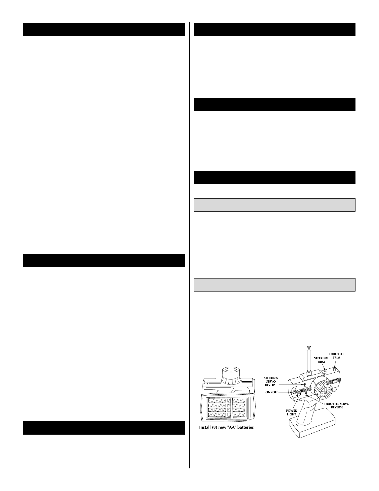
❍ 1. Remove the transmitter antenna from the parts bag and screw
it into the top of the transmitter. To ensure that the antenna is
attached, lightly pull on the base of the antenna. If it slides out, it is
not installed properly.
❍ 2. Slide off the battery door on the bottom of the transmitter. Install
8 new “AA” batteries in the configuration molded into the battery
holder. Replace the battery door.
Transmitter Assembly
Decals
FINAL ASSEMBLY
TOOL BOX ITEMS YOU MAY NEED
ITEMS REQUIRED FOR COMPLETION
SPECIFICATION & DESCRIPTION CHANGES
REPAIR SERVICE
SAFETY PRECAUTIONS
2
Page 3

❍ 3. Turn on the transmitter using the switch on the front. The red
LED light next to the on/off switch should light up. If the LED does
not light up, turn off the transmitter and check to make sure that the
batteries are installed properly. If you see a flashing LED, the batteries
are low and need to be replaced.
❍ 1. Remove the body pin toward the rear of the hatch cover and
carefully remove the hatch.
❍ 2. Using a small Phillips screwdriver, remove the two 1.6 x 17mm
screws and carefully lift the radio box cover.
❍ 3. Uncoil the receiver antenna wire and route it through the small
hole in the rear wall of the radio box. Replace the radio box cover
and secure it with the two 1.6 x 17mm screws.
❍ 4. Run the receiver antenna wire up through the antenna tube
mount (the small opening located toward the rear of the hatch).
❍ 5. Thread the receiver antenna wire through the antenna tube and
insert the antenna tube into the antenna tube mount. DO NOT CUT
OFF THE EXCESS ANTENNA WIRE!
❍ 1. Plug a fully charged battery pack into the speed control’s battery
connector and position the pack as shown in the photo. Use the
included hook and loop material to hold the battery pack in place.
❍ 2. Turn on the transmitter and then, move the boat’s ON/OFF
switch to the “ON” position.
Installation of the Battery Pack
Receiver Antenna
3
Page 4

❍ 3. Replace the hatch and body pin.
•
Standing behind the boat with both the vessel and transmitter
powered up, rotate the transmitter’s steering wheel to the left. The
back of the rudder should move towards the left. Move the wheel to
the right. The back of the rudder should move towards the right. If
this is not the case, simply move the steering servo reverse switch to
the other position.
•
Squeeze the trigger on the transmitter. This should make the
propeller rotate counterclockwise. Conversely, pushing the trigger
forward should make the propeller rotate clockwise.
•
The electronic speed control is factory set. No other adjustments
are needed. If the motor still rotates when you let off of the trigger,
adjust the throttle trim on the transmitter.
•
Before operating your Turbo Vee II, it is a good idea to make sure
all screws are securely fastened.
•
Place the boat in water that is at least 8" deep and free of
obstacles (weeds, sticks, wildlife, etc.).
•
Periodically remove the driveshaft and relube with a thin coat of
petroleum jelly or light grease.
•
Slowly advance the throttle to full speed and note if the boat has
a tendency to turn right or left. Adjust the steering trim knob on your
transmitter until the boat will run in a straight line, when the steering
wheel is at neutral.
•
CAUTION: Windy conditions cause rough water that will affect
the performance of your Turbo Vee II and increase the chances of
capsizing.
•
Total run time of the Turbo Vee II will be approximately 5
minutes
(assuming you begin with fully charged battery pack). When you
notice a decrease in the power of the motor, it’s time to head for
shore.
•
CAUTION: Some of the electronic components may become
hot! Allow a minute or two to let your motor and speed control cool
off before changing the battery pack.
•
Your Turbo Vee II may occasionally take on small amounts of
water, especially when running in rough water or when making tight
turns. Keep a roll of paper towels handy and dry out the hull interior
after every run. If you notice excessive amounts of water in the hull,
check for leaks, especially around the hull/deck joint. You may reseal
the joint using medium cyanoacrylate (CA) glue.
•
Always store your Turbo Vee II with the hatch removed to allow
the interior to dry out completely. Failure to do so may result in
corrosion of the electronic components.
•
IMPORTANT: If, for whatever reason, your boat takes on a large
amount of water, swamps or sinks, causing the electronics to get
wet, you must do the following immediately: Remove the battery
pack and all radio equipment from the boat. Allow the components
to air dry completely before reassembling. Reinstall the components
and check for proper operation before running the boat in water.
•
Avoid running the boat in cold weather. The hull and other
plastic parts can become brittle at low temperatures. In addition,
grease and oil can become thick, causing premature wear and poor
performance.
If the boat quits:
If your Turbo Vee II should happen to capsize or quit, water currents
will slowly carry it to shore. The boat could be carried to the
opposite shore, so it is advisable to notice things like wind direction,
size of the lake, strength of river currents, etc., when surveying areas
to run your Turbo Vee II.
Use a fishing rod with at least 12 lb. test line and a tennis ball tied
to the end, to retrieve a stalled or capsized model boat.
GOOD LUCK AND GREAT BOATING!
To order replacement parts for the Turbo Vee II, use the order
numbers in the Replacement Parts List that follows. Replacement
parts are available only as listed and can be purchased from Tower
Hobbies.
Replacement Parts List
Order # Description Includes
TOWB4590 Prop Set (2) Props, (2) Washers, (1) Nut,
(1) Lock Nut.
TOWB4595 Prop Shaft Set (1) Shaft, (1) Brass Tube, (1)
Coupler,
(2) Set Screws.
TOWB4650 Rudder Set Rudder, Rudder Mount, Rudder H
orn,
with Hardware.
TOWB4800 Trim Tabs (1) Left and (1) Right Trim Tab with
Hardware.
TOWB4280 Speed Control (1) Electronic Speed Control.
ORDERING REPLACEMENT PARTS
Helpful Tip
Operation of the Turbo Vee II
Check the Radio System
 Loading...