

Page 1
WARRANTY
Tower Hobbies®guarantees this kit to be free from defects in both material and workmanship at the date of purchase. This warranty
does not cover any component parts damaged by use or modification. In no case shall Tower Hobbies' liability exceed the original
cost of the purchased kit. Further, Tower Hobbies reserves the right to change or modify this warranty without notice.
In that Tower Hobbies has no control over the final assembly or material used for final assembly, no liability shall be assumed nor
accepted for any damage resulting from the use by the user of the final user-assembled product. By the act of using the
user-assembled product, the user accepts all resulting liability.
If the buyers are not prepared to accept the liability associated with the use of this product, they are advised to return this kit
immediately in new and unused condition to the place of purchase.
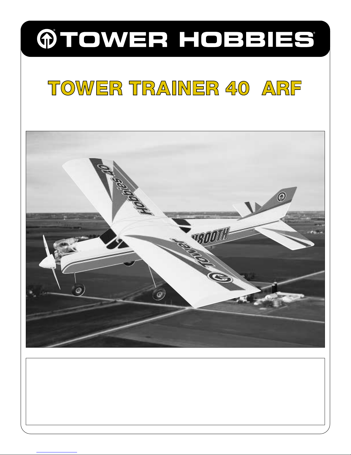
ASSEMBLY INSTRUCTIONS
WINGSPAN: 60 IN.
LENGTH: 50 IN.
WING AREA: 660 SQ. IN.
WEIGHT: 5.5 LBS.
WING LOADING: 19.2 OZ./SQ. FT.
© Copyright 2000 V1.0
™
ALMOST READY-TO-FLY RADIO CONTROLLED MODEL AIRPLANE
TOWZ1149 for TOWA1100
Page 2
Page
INTRODUCTION.......................................................2
PRECAUTIONS...........................................................2
SUGGESTED TOOLS & SUPPLIES ..............................2
ACCESSORIES REQUIRED TO COMPLETE
YOUR T OWER TRAINER 40 .......................................3
ENGINE SELECTION ..................................................3
ORDERING REPLACEMENT PARTS............................3
TOWER TRAINER GUARANTEE .................................3
PARTS LIST.................................................................4
WING ASSEMBL Y.......................................................5
FUSELAGE ASSEMBLY ................................................7
LANDING GEAR INSTALLATION ............................10
FUEL TANK INSTALLA TION.....................................11
ENGINE INSTALLATION..........................................12
RADIO INSTALLATION............................................13
RADIO SYSTEM SET-UP ...........................................17
BALANCE YOUR MODEL.........................................18
PREP ARING TO FL Y YOUR T OWER
TRAINER 40 .............................................................19
AMA SAFETY CODE.................................................20
FL YING YOUR T OWER TRAINER 40 ........................20
SOME MODELING TERMS & TRIVIA .......................22
Congratulations! You’re about to build in a few days what took
pioneers years - a powered machine that flies. Specially created for
you and other first-time radio control modelers, the Tower Hobbies
Tower Trainer 40 ARF offers nearly all the excitement of piloting a
real airplane...and develops skills that will take you anywhere you
want in your new hobby.
PROTECT YOUR MODEL, YOURSELF & OTHERS
FOLLOW THIS IMPORTANT SAFETY PRECAUTION
Your Tower Trainer .40 is not a toy, but rather a sophisticated,
working model that functions very much like a full size airplane.
Because of its realistic performance, the Tower Trainer .40, if not
assembled and operated correctly, could possibly cause injury to
yourself or spectators and damage property.
To make your R/C modeling experience totally enjoyable, we
recommend that you get experienced, knowledgeable help with
assembly and during your first flights. You’ll learn faster and avoid
risking your model before you’ re truly read y to solo. Your local hobby
shop has information about flying clubs in your area whose
membership includes qualified instructors.
You can also contact the national Academy of Model Aeronautics
(AMA), which has more than 2,500 chartered clubs across the
country.
Through any one of them, instructor training programs and insured
newcomer training are available.
Contact the AMA at the address or
toll-free phone number below:
We recommend Great Planes®, Hobbico®and Tower brand glues
and accessories for your modeling needs
❍ (2) T ower Build-It
™
Thin CA 2 oz. – TOWR3800
❍ (2) Tower Build-It Medium CA+ 2 oz. – TOWR3801
❍Tower Build-It Thick CA 1 oz. – TOWR3802
❍Tower Hobbies 6-minute Epoxy – TOWR3806
❍Tower Hobbies 30-minute Epoxy – TOWR3810
❍ Hand or Electric Drill
❍ Drill Bits: (1/16", 1/8", 5/32", 3/16")
❍ Hobby Saw (X-Acto
®
Razor Saw)
❍ Hobby Knife, #11 Blades
❍ Pliers
❍ Screwdrivers (Phillips and Flat Blade)
❍ Flat File (or Similar Tool)
❍T-Pins (Short – HCAR5100, Long – HCAR5200)
❍ String
❍ Straightedge with Scale
❍ Masking Tape (Required for Construction)
❍ Sandpaper (Coarse, Medium, Fine Grit)
❍ Great Planes Easy Touch
™
Bar Sanders (or Similar)
❍ Waxed Paper
❍ Dremel
®
Multi-Pro™or Similar (Optional)
SUGGESTED SUPPLIES & TOOLS
Academy of Model Aeronautics
5151 East Memorial Drive
Muncie, IN 47302-9252
Office: (765) 287-1256
Toll Free: (800) 435-9262
FAX: (765) 741-0057
READ THROUGH THIS INSTRUCTION BOOK FIRST. IT
CONTAINS IMPORTANT INSTRUCTIONS AND WARNINGS
CONCERNING THE ASSEMBLY AND USE OF THIS MODEL.
PRECAUTIONS
INTRODUCTION
TABLE OF CONTENTS
2
Page 3
3
❍ 4-Channel Radio With 4 Servos
❍ Engine;
(See Engine Selection)
❍ Spare Glow Plugs (Tower R/C Long – TOWG1001)
❍ Medium Fuel Tubing (GPMQ4131, 3’)
❍ 1/4” Latex Foam Rubber Padding (HCAQ1000)
❍ 1/16” Foam Wing Seating Tape (GPMQ4422)
❍ #64 Rubber Bands (TOWQ1220)
❍ Screw-Lock Pushrod Connectors (GPMQ3870)
❍ Silicone Sealer
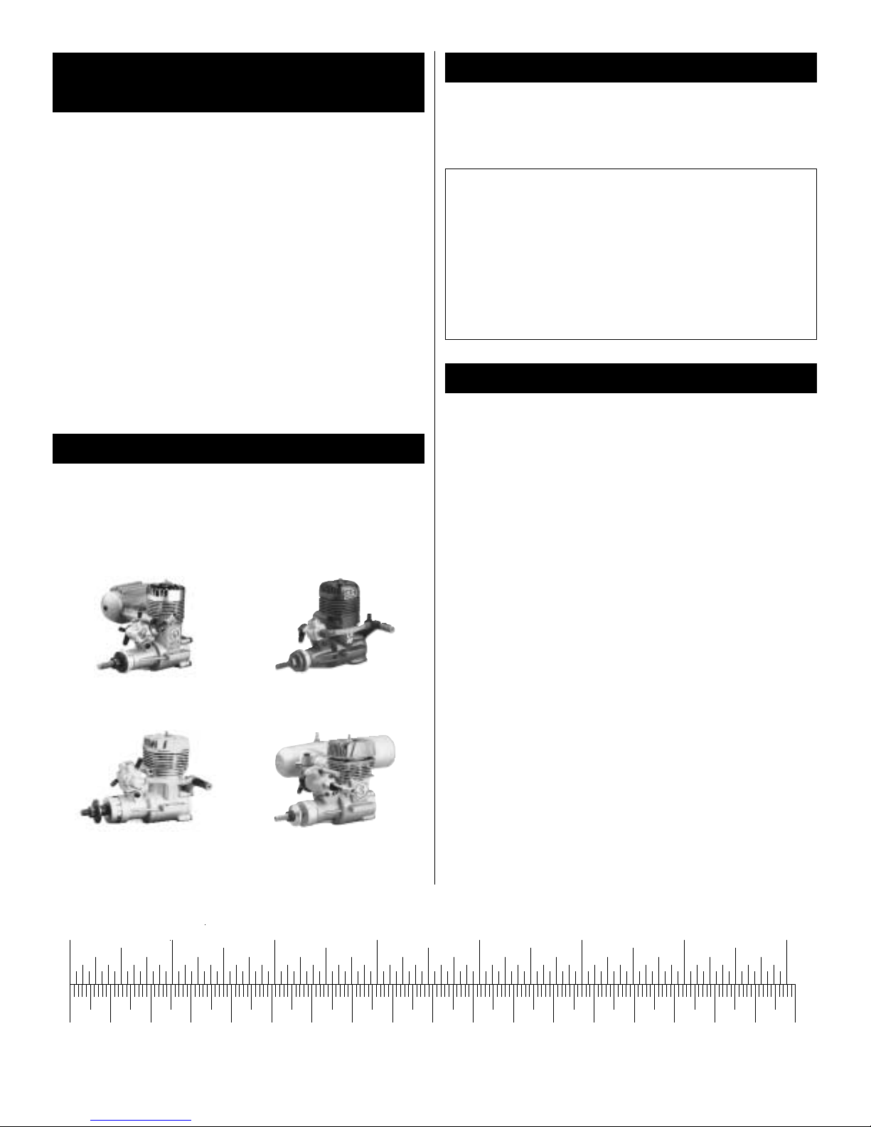
A quality brand .40-size engine will be needed. Also a prop will be
required for the engine (follow the manufacturer’s recommendations
for appropriate sizes). We recommend the Top Flite
®
Power Point
®
brand of props.
We recommend the following engines:
Tower Hobbies .40 ABC O.S.
®
.40 LA
TOWG0040 OSMG0040
O.S. .40 FX SuperTigre®GS-40
OSMG0540 SUPG0122
Replacement parts are available from Tower Hobbies for your Tower
Trainer 40. Our order assistance representatives are ready to answer
your questions or to place your order. Call us at (800) 637-6050.
We are so confident that the Tower Trainer 40 ARF is the best almostready-to-fly trainer available that we make this guarantee. You will
successfully learn how to fly with the Tower Trainer or we will replace it
with your choice of another trainer of up to equal value. All we ask is that
you learn under the supervision of a qualified, club-designated instructor ,
follow normal safety precautions, fly at an AMA-chartered club field and
construct the kit as outlined in this instruction manual.
If for some reason, you find the design and/or workmanship of the
T o wer T rainer is not conduci ve to learning to fly under the conditions
outlined above, contact Hobby Services at 1-217-398-0007 Monday
through Friday 9am-5pm central time. Or send the Tower Trainer to
Hobby Services, 1610 Interstate Drive, Champaign, Illinois 61822.
The information Hobby Services will need is: a letter explaining w hat
happened, (the letter is to be signed by the instructor and yourself),
name of flying field, name of instructor, and a copy of invoice as
proof of purchase.
This guarantee is effective for 60 days after you receive the kit and
does not cover incidental items (engines, radio equipment and
hardware, etc.). The kit, along with the above specifications must be
sent to Hobby Services for inspection no later than 60 days after
receipt of the kit. Hobby Services reserves the right to verify all
information provided. Replacement trainer kit options are limited to
flat-bottom wing trainer models and makes available from Tower
Hobbies and one replacement per customer.
The T ower T rainer 40 ARF is a great tr ainer and we are pleased to make
this unprecedented guarantee. If you have any further questions, feel
free to contact Tower Hobbies at 1-800-637-6050.
TOWER TRAINER GUARANTEE
Replacement Parts
Wing Set – TOWA1111 (Includes wing halves, wing joiner and
servo mounting tray)
Fuselage Set – TOWA1112 (Includes fuselage, engine mount, fuel
tank, pushrods and servo tray)
Fin Set – TOWA1113 (Includes horizontal and vertical stabilizers)
Landing Gear Set – TOWA1114 (Includes nosegear wire, main
gear wire, wheels, wheel collars, mounting hardware)
ORDERING REPLACEMENT PARTS
ENGINE SELECTION
ACCESSORIES REQUIRED TO COMPLETE
YOUR TOWER TRAINER 40
Inch Scale
0" 1" 2" 3" 4" 5" 6" 7"
0 10 20 30 40 50 60 70 80 90 100 110 120 130 140 150 160 170 180
Metric Scale
Page 4
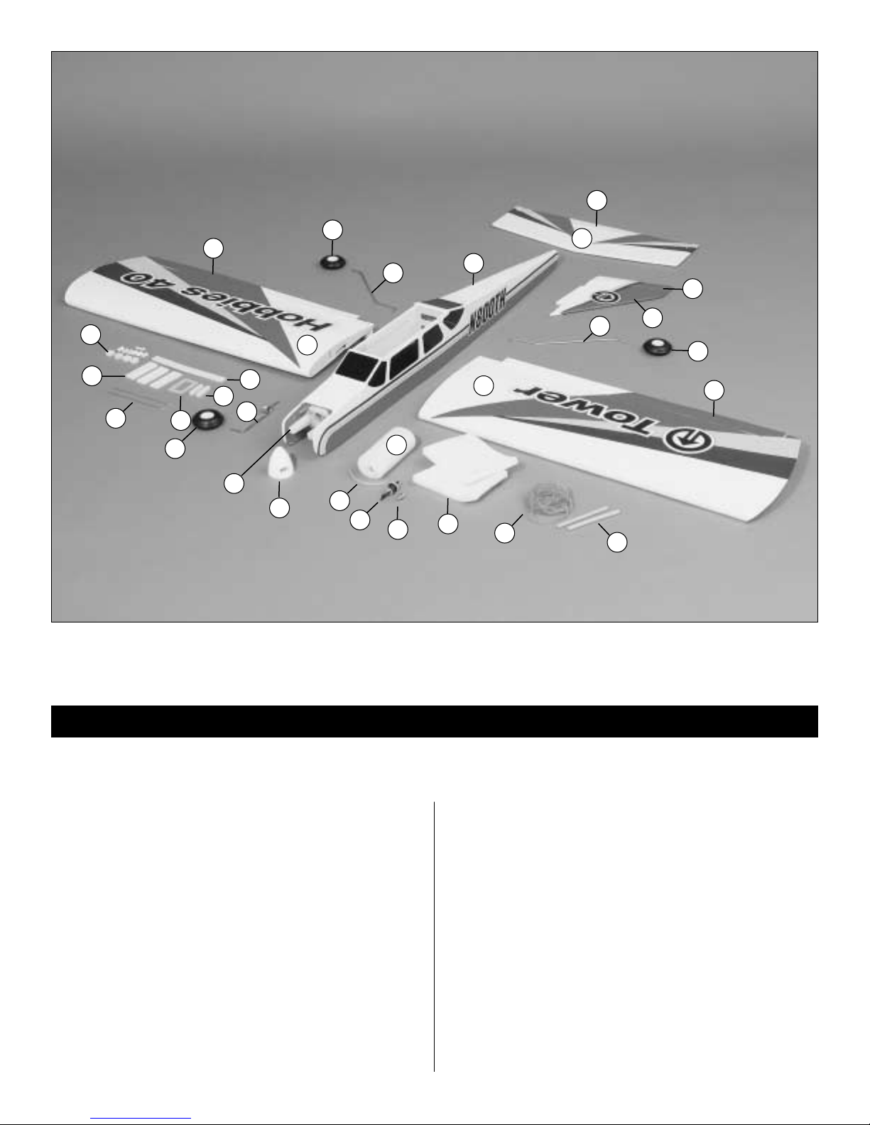
1 Fuselage
2 Left Wing Panel
3 Right Wing Panel
4 Stabilizer
5 Elevator
6 Rubber Bands
7 Foam Rubber
8 Engine Mount
9 Left Aileron
10 Right Aileron
11 Pushrod Assembly (2 pcs., Not Shown)
12 Pushrod Housing (2 pcs., Not Shown)
13 Pushrod Wire (Long – 2 pcs., Not Shown)
14 Pushrod Wire (Short – 2 pcs., Not Shown)
15 Spinner Assembly (53mm/2 in.)
16 Plastic Part Set (Not Shown)
17 Rudder
18 Fin
19 Pushrod Supports
20 Receiver Battery Retainers
21 Aileron Pushrods
22 Fuel T ank Stopper
23 Plywood Wing Joiner
24 Fuel T ank
25 Main Landing Gear (2 pcs.)
26 Fuel T ank Clunk
27 Silicone Fuel Tubing
28 Aileron Servo Tray Mounting Blocks
29 Aileron Servo Tray
30 Nose Landing Gear Wire
31 Wing Mounting Dowels (2 pcs.)
32 Wheels (64mm/2-1/2 in. – 3 pcs.)
4
PARTS LIST
1
5
4
17
18
32
25
9
2
7
6
31
26
22
27
24
15
8
30
32
23
29
28
21
19
20
3
10
32
25
Before assembly match the parts in the photo with the parts in the kit. Check off each part as it is located. If any parts are missing or damaged,
consult Tower Hobbies Order Assistance (see back cover page for phone numbers).
Note: All Parts Are 1 Piece Unless Otherwise Stated.
Page 5
Special Note:
It is suggested to charge your radio system before starting to build.
Following the manufacturer‘s instructions, connect your transmitter
and receiver batteries to the system‘s charger. This way the radio will
be ready when it is time to install and test the radio components.
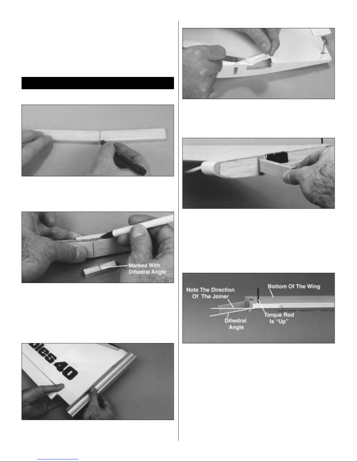
MARK THE CENTERLINE ON THE JOINER
❍ 1. Draw a centerline on both sides of the plywood wing joiner
as shown.
PREPARE THE AILERON SERVO TRAY MOUNTING BLOCKS
❍ 2. Locate the two 3/8" square x 1-11/16" (9.5mm square x 43mm)
aileron servo tr ay mounting blocks. Mark a centerline on the blocks.
Using the wing joiner as a guide, mark the wing dihedral angle on
both of the aileron mounting blocks. Set the blocks aside for use in
later steps.
EVEN THE WING ROOTS
❍ 3. Using a flat sanding block or similar tool and 120-grit sandpaper,
sand the wing roots so they will fit together without any gaps. Do not
sand too much or the dihedral angle could change.
PREPARING THE WING SERVO CAVITY
❍ 4. Using a sharp hobby knife, remove the covering from the wing
panels for the aileron servo.
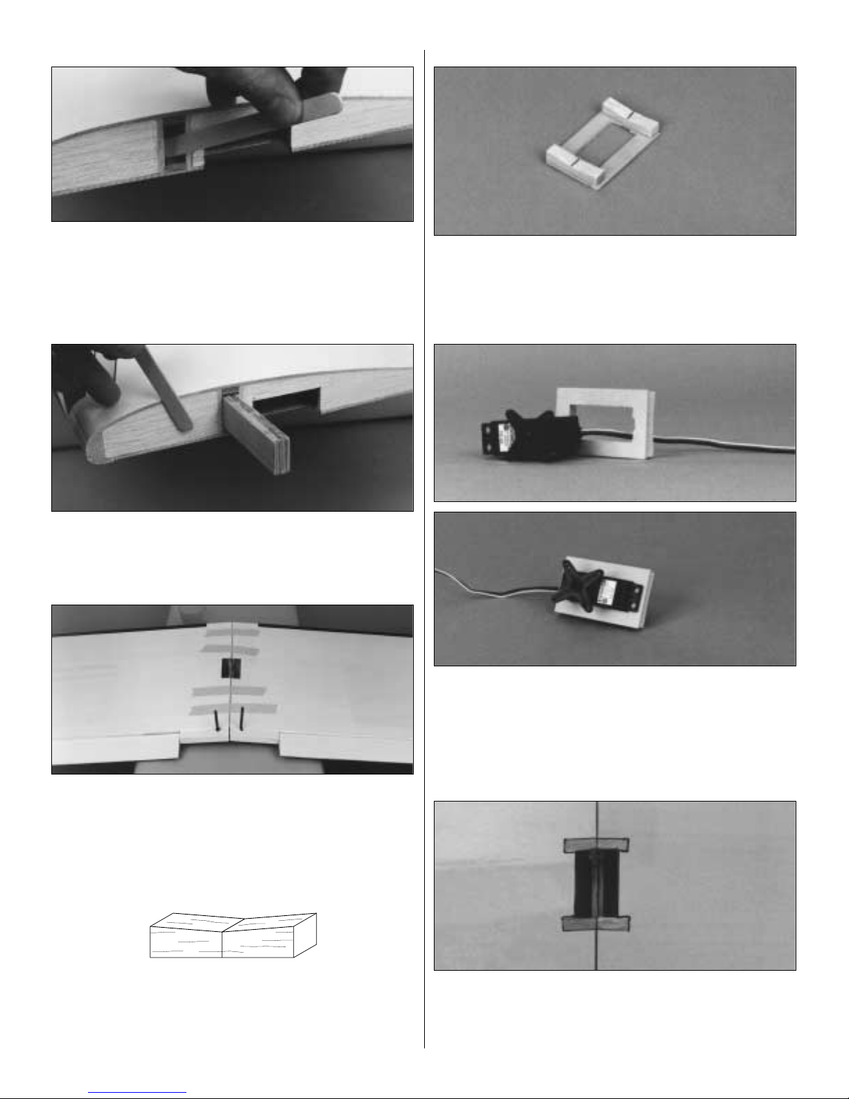
TEST FIT THE WING JOINER
❍ 5. Test fit the wing joiner in both wing panels by sliding the joiner
into the joiner cavity in the wing. The joiner should slide in with little
resistance up to the centerline that was drawn on the joiner. If the
joiner will not fit in the cavity, lightly sand any uneven surfaces from
the joiner edges, sides or ends. Caution: A snug fit of the joiner in the
joiner cavity is desired. Use caution not to sand the joiner excessivel y .
VIEWING THE WING DIHEDRAL
❍ 6. Pay close attention to the orientation of the wing joiner in
relation to the wing panel, creating the dihedral angle as shown. Test
fit the wing panels together. They should fit flush against each other
without any gaps.
Note: When performing the following steps, be sure to use a
sufficient amount of epoxy to form a complete and solid bond
between the plywood wing joiner and the two wing halves. This is
the most important glue joint in the entire airplane.
Please read through the following three steps before mixing any
epoxy. You must complete these steps within 20 minutes from the
time you mix the epoxy.
WING ASSEMBLY
5
Page 6
GLUE THE JOINER CAVITY
❍ 7. Mix 1/2 oz. (14ml) of 30-minute epoxy. Use a mixing stick or
epoxy brush to apply epoxy to all four sides of the joiner cavity.
Insert the joiner into the cavity up to the centerline marked on the
wing joiner. Be sure y ou are installing the joiner to obtain the correct
direction for the dihedral. Quickly proceed to the next step.
APPLY EPOXY TO THE WING ROOT
❍ 8. Apply epoxy inside the joiner cavity of the remaining wing
panel. Next, coat the wing root ribs on both panels. Quickly proceed
to the next step.
JOIN THE WING HALVES
❍ 9. Assemble the two wing halves with the tightest seam possible.
No gaps should be showing between the two halves. Clean up any
excess epoxy from the outside of the wing using a paper towel and
rubbing alcohol. Use several strips of masking tape on both sides of
the wing to hold them securely together. Let the epoxy fully cure
before continuing.
SHAPE THE AILERON SERVO MOUNTING BLOCKS
❍ 10. Locate the two aileron servo mounting blocks and position
them with the dihedral line up. Cut or sand the marked angle out of
the block. This angled side will be placed against the wing when the
servo tray is installed.
ASSEMBLE THE SERVO TRAY
❍ 11. Glue the balsa aileron servo mounting blocks onto the aileron
servo tray using either 6-minute epoxy or medium CA. Make sure
that the angled side you just cut is facing away from the plywood
servo tray.
TEST FIT THE AILERON SERVO
❍ 12. T est fit the aileron ser vointo the servo tra y. Note that the notch
in the tray corresponds to the location of the servo lead wire. Enlarge
the opening in the servo tray, if needed, using a sharp hobby knife or
fine toothed file. There should be a gap of about 1/64" (.5mm)
between the servo and the servo tray when installed properly.
Remove the servo for the time being.
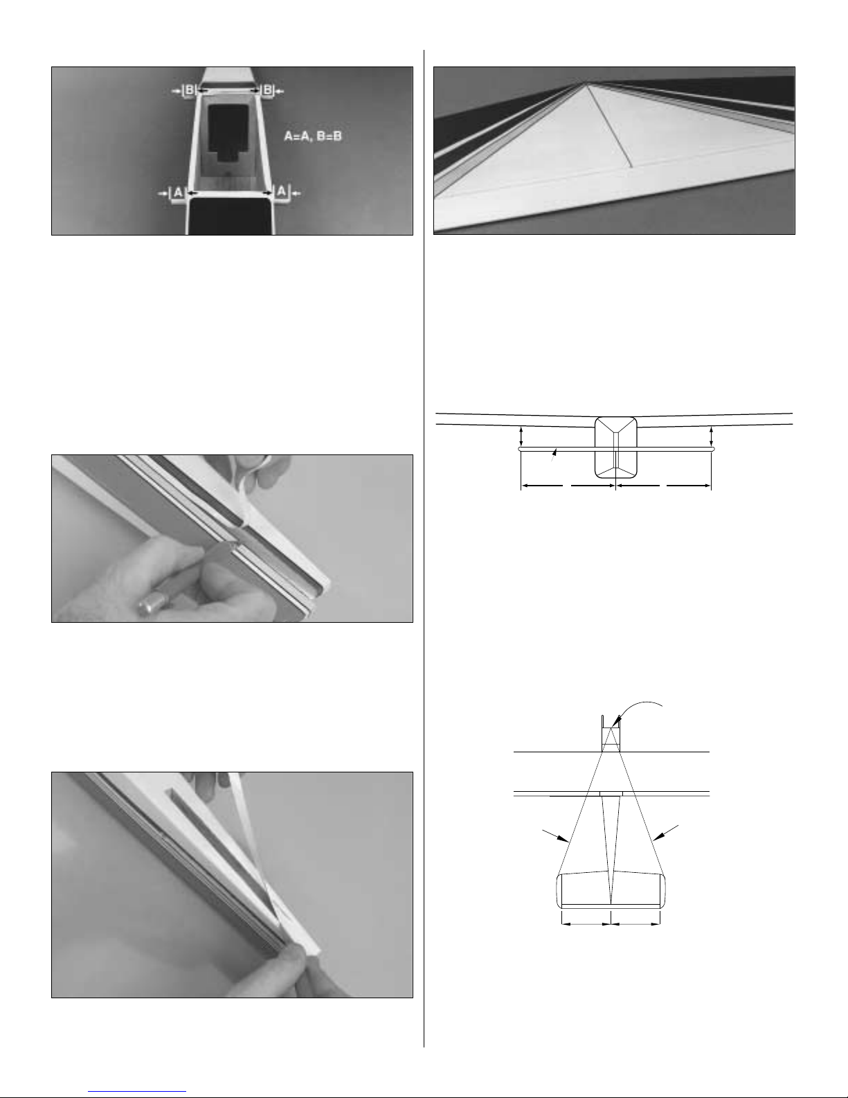
TRIM THE WING COVERING
❍ 13. Hold the plywood aileron servo tray assembly over the hole
in the bottom of the wing. Trace the outside of the blocks with a
felt-tip marker, then remo ve the tr ay from the wing. Carefully r emov e
the covering within the lines using a sharp hobby knife with a new
blade, being careful not to cut into the balsa wing sheeting.
6
Page 7
7
INSTALL THE SERVO TRAY
❍ 14. Mix 1/8 oz. (3.5ml) of 6-minute epoxy to glue the servo tray
to the bottom side of the wing. Apply equal amounts of epoxy to the
mounting blocks on both ends of the servo tray. Attach the servo tray
to the bottom of the wing with the notch in the servo tray facing
towards the leading edge of the wing. Allow the epoxy to fully cure
before proceeding to the next step.
APPLY THE WING CENTER SECTION TAPE
❍ 15. Starting at the front of the aileron servo tray, apply the 1/2"
(13mm) white wing center section tape completely around the wing
over the joint. A small amount of pressure should be applied to make
a smooth seam.
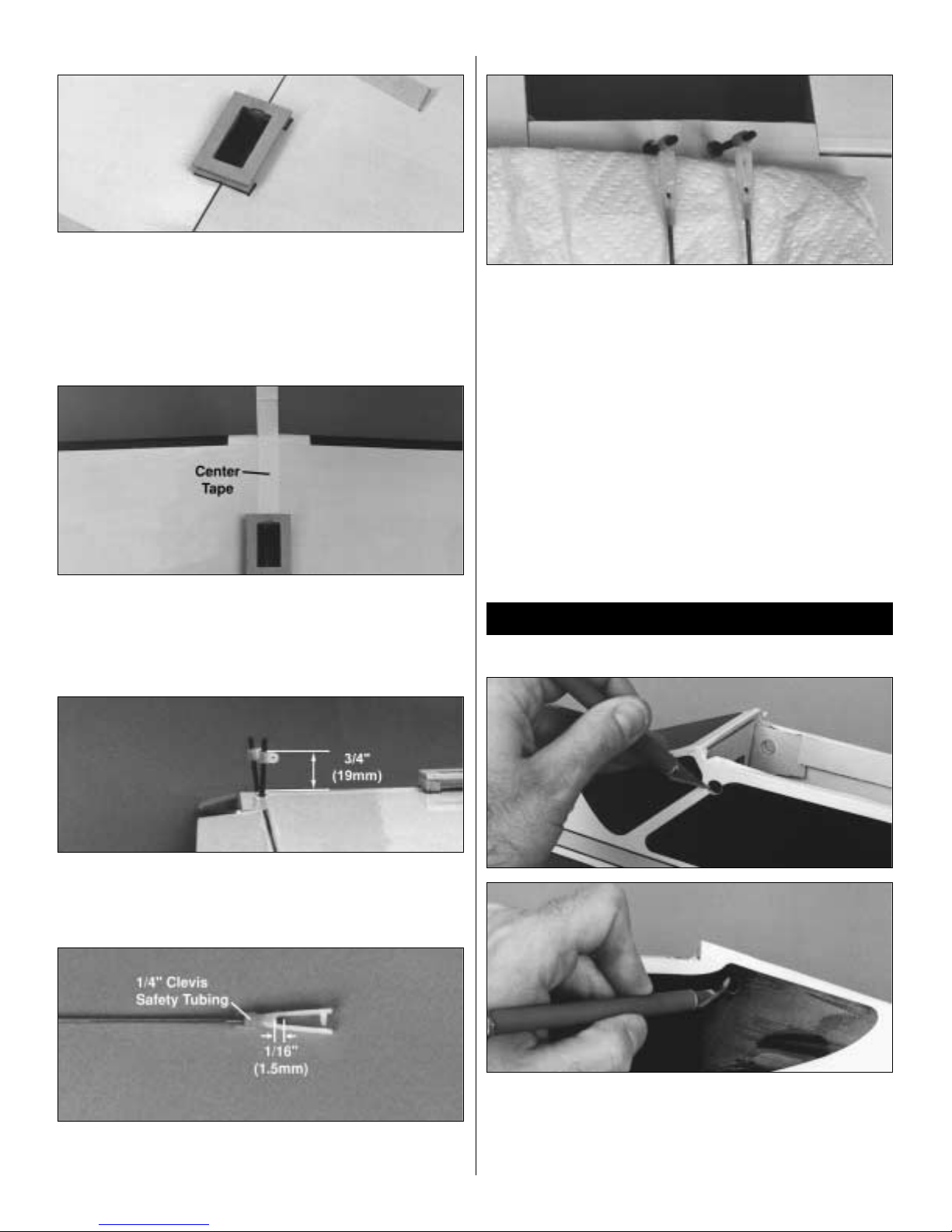
INSTALL THE AILERON CONTROL HORNS
❍ 16. Thread the aileron control horns onto the torque rods until
they are positioned 3/4" (19mm) above the bottom of the wing.
ASSEMBLE THE PUSHRODS
❍ 17. Locate two plastic clevises and two 6-3/4" (171mm) aileron
pushrods. Thread the clevises onto the rods so that 1/16" (1.5mm) of
the rod protrudes between the clevis forks.
INSTALL THE PUSHRODS
❍ 18. Attach the pushrods to the aileron control horns. If the pins
from the clevises do not fit the holes in the horns, drill the holes out
to 1/16" (1.5mm). Press the forks of the clevises together until the pin
snaps into the opposite fork. Slide the safety tubing into position over
the clevis.
Note: The paper towel in the photo is only there for
photographic purposes. You do not need to install the paper towel
on your aircraft.
This concludes the wing assembly for now. Tape the pushrods to the
wing to keep them in place until the aileron servo is installed.
LOCATE THE WING DOWEL HOLES
❍ 1. Locate the four positions for the 1/4" (6mm) wing dowel holes
by gently pressing the covering in the areas in the photos. The
position for the front wing dowels can be seen from the inside of the
fuselage. Carefully cut out the holes using a sharp hobby knife.
Caution: Do not cut out any of the rectangular holes in the sides of
the fuselage.
FUSELAGE ASSEMBLY
Page 8
INSTALL THE WING MOUNTING DOWELS
❍ 2. Insert both wing mounting dowels so they protrude an equal
amount on both sides of the fuselage. Mix 1/4 oz. (7ml) of 30-minute
epoxy. Apply glue around the dowels next to the fuselage and slide
them in and out of the fuselage to help distribute the epoxy into the
fuselage. Using a paper towel, spread the excess epoxy around the
ends of the dowels. This will fuelproof and add strength to the wood.
From the inside of the fuselage, apply more epoxy around the dowels
where they meet the sides of the fuselage. These wing dowels will be
used as the anchors for the rubber bands to hold the wing in position.
Wipe off all excess epoxy using a paper towel and rubbing alcohol.
LOCATE THE STABILIZER SLOT
❍ 3. Locate the slot for the horizontal stabilizer under the covering
on the tail section of the fuselage by gently pressing the covering
with your finger. The slot is located on both sides of the fuselage.
Using a sharp hobby knife, carefully remove the covering, exposing
the slots. Note: Do not cut into the wood around the slot.
LOCATE THE VERTICAL FIN SLOT
❍ 4. Using the same technique as in step 3, locate the slot for the
vertical fin on the top of the fuselage. Remove the covering using a
sharp hobby knife.
MARK THE CENTERLINE
❍ 5. On the top surface of the horizontal stabilizer, measure to find
the exact center from side to side. Draw a “centerline” using a felt-tip
pen. Next, extend that centerline onto the trailing edge, in the gap,
as shown in the photo. (DO NOT MARK ON THE ELEVATOR WHEN
PERFORMING THIS STEP.)
ALIGN THE STABILIZER WITH THE WING
Note: Do not use any glue until instructed to do so.
❍ 6. Insert the stabilizer into the horizontal stabilizer slot so it is
centered in the fuselage (A). Place the wing onto the fuselage and
secure with two rubber bands. View the plane from a distance of
about 8 feet (2.4m) to check the alignment of the stabilizer to the
wing (B). If the stabilizer is not parallel to the wing, remove the
stabilizer and sand the stabilizer base slightly on the high side.
Replace the stabilizer and check the alignment. Continue this
process until the wing and stabilizer are parallel.
ALIGN THE STABILIZER WITH THE FUSE
❍ 7. Attach a piece of string with a T-pin to the center of the fuselage
as shown. Hold the string to one corner of the horizontal stabilizer.
Mark the position on the line, then swing the line over to the
opposite tip on the stabilizer. If the mark does not line up, adjust the
positioning of the stabilizer and repeat the “mark and swing”
procedure until the stabilizer is in proper alignment.
8
Wing
B
A
A=A
B=B
B
Horizontal
Stabilizer
Fuse
A
Wing/Stab Align
T-PIN
STRING
EQUAL MEASUREMENTS
STRING
Page 9

MARK THE STABILIZER LOCATION
❍ 8. With the stabilizer properly aligned, use a felt-tip pen to trace
around the tail of the airplane on the top and bottom of the
horizontal stabilizer.
REMOVE THE CENTER COVERING
❍ 9. Remove the stabilizer and dra w two additional lines, on the top
and bottom, 1/16" (1.5mm) inside the lines drawn in the previous
step. Next, carefully cut through the covering using a new #11 knife
blade at the inside lines and remove the covering from the center . Do
not cut the wood under the covering! This will seriously w eaken the
stabilizer and could easily cause the stabilizer to break in flight. If
the stab breaks, the plane has a very good chance of crashing. It is
best to be very careful when making this cut not to cut into the
wood. The covering does need to be removed from the center of the
stab, or the bond between the stabilizer base and stabilizer will be
insufficient and the stab may simply come off in flight.
INSTALL THE STABILIZER
❍ 10. Mix 1/4oz (7ml) of 30-minute epoxy. Using a mixing stick,
place glue inside the horizontal stabilizer slot on all sides, and a
good layer of epoxy on the stabilizer base. Place a thin la yer of epoxy
on the stabilizer in the area where the covering was removed. Insert
the stabilizer into the slot from the rear and check the alignment.
Wipe off any epoxy that squeezes out using a paper towel and
rubbing alcohol. Recheck the alignment several times while the
epoxy cures.
INSTALL THE VERTICAL FIN
❍ 11. Test fit the vertical fin into the slot on the top of the fuselage.
Sand the edges of the slot if necessary for a snug fit. When fit
properly the bottom of the vertical fin will rest on the top of the
horizontal stabilizer. Remove the fin and mix up 1/4oz (7ml) of
30-minute epoxy. Using a mixing stick, apply epoxy to the top of the
stabilizer through the slot. Apply epoxy to the sides and bottom of
the fin base that have the balsa wood exposed. Insert the fin into the
slot. Check to make sure that the fin is perpendicular to the stabilizer
when viewed from the rear of the airplane. (Use the sketch as a guide
for checking the alignment.) Check this alignment several times as
the epoxy cures. (You may find it beneficial to hold the fin in place
using masking tape until the epoxy has cured.)
CUT THE RUDDER PUSHROD EXIT
❍ 12. The precut rudder pushrod exit hole is located on the top of
the fuselage on the left side of the fin. Locate the exit hole by gently
running your finger along the top of the fuselage over the covering.
It should be beside the rudder as shown in the photo. Use a hobby
knife to remove the covering from the rudder pushrod exit hole.
CUT THE ELEVATOR PUSHROD EXIT
❍ 13. The precut elevator pushrod exit hole is located on the right
side of the fuselage. Locate the exit hole by gently running your
finger along the side of the fuselage over the covering. It should be
slightly in front of the elevator as shown in the photo. Use a hobby
knife to remove the covering from the elevator pushrod exit hole.
9
90˚
90˚
Page 10

LOCATE THE LANDING GEAR CHANNEL
❍ 1. On the bottom of the fuselage, there is a channel for the main
landing gear. Locate this channel by running your finger over the
covering on the bottom of the fuselage. Use a hobby knife to remove
the covering from this channel.
PREPARE THE CHANNEL FOR GEAR
❍ 2. Test fit the chrome landing gear wires into the holes in the
channel. If they will not go in easily, drill out the two holes using a
5/32" (4mm) drill bit. Next, use the drill bit or hobby knife to bevel
the inside corners of the holes so that the bend in the wire will seat
fully into the holes and the wire will be flush with the bottom of
the fuselage.
ATTACH THE LANDING GEAR WIRES TO THE FUSELAGE
❍ 3. Install the landing gear wires into the channel. Attach the
nylon landing gear straps to the fuselage using four 3 x 12mm sheet
metal screws. The holes for the screws are pre-drilled.
INSTALL THE STEERING PUSHROD
❍ 4. Attach the “Z” bend of the wire to the hole on the steering arm.
Slide the wire into the pushrod housing so that the screw on the
steering arm is facing forward. The wire should be on the bottom of
the steering arm.
INSTALL THE NOSE LANDING GEAR WIRE
❍ 5. Install the nose landing gear wire through the nose gear
bracket. Next, the wire will go through the steering arm. Holding the
steering arm against the bearing, slide the wheel collar and tighten it
into position.
PREPARE THE AXLES AND INSTALL THE WHEEL COLLARS
❍ 6. Prepare the axles for the wheel collars by filing a 3/4" (19mm)
flat spot on the outer edge of the main and nose gear. This is done to
prevent the wheel collar from turning or becoming loose during
flight. Perform this step for both of the main gear and the nose gear.
Secure one of the wheel collars 1-3/8" (35mm) from the end of the
axle on the main gear using a M3 x 6 machine screw. The first wheel
collar on the nose gear will slide fully onto the gear, against the
bend. A total of three wheel collars and three 3 x 6mm machine
screws should have been used during this step.
LANDING GEAR INSTALLATION
10
Page 11

INSTALL THE WHEELS
❍ 7. Slide the wheels onto the axles, making sure that they spin
freely on the axles. If not, drill the hole in the wheel out until it can
spin freely.
SECURE THE WHEELS
❍ 8. Install the wheel collars and 3 x 6mm screws onto the axles.
Position the screw so that it will be tightened onto the flat spot you
made on the axle. Slide the wheel collar next to the wheel, and
tighten the screw. Double check the wheel to make sure it still spins
freely . If not, mo ve the w heel collar aw a y from the wheel
slightly
and
retighten the screw.
If you like, you can cut off the excess axle that
extends past the wheel collar.
PREPARE THE VENT TUBE
❍ 1. Bend one of the tubes (referred to as the vent tube) upwards at
around a 45-degree angle. Heating the tube will make the bending
process much easier. Be very careful not to melt the tube during the
bending process. Note: When the stopper assembly is installed into
the fuel tank, the vent tube should be 1/16" [1.5mm] from the top of
the tank.
INSTALL THE CLUNK
❍ 2. Locate the metal fuel pick-up weight (often referred to as the
"clunk") and the 4-1/4" [108mm] piece of silicone fuel tubing. Install
the clunk onto the tubing. Slide the other end of the tubing onto the
tube that was not bent in the previous step. Measure the distance
from the end of the clunk to the back of the stopper. Position the fuel
tube so the distance measures 5" [127mm].
INSTALL THE STOPPER ASSEMBLY
❍ 3. The stopper assembly can now be inserted into the tank. The
vent tube should be adjusted so that the tube is pointed straight up
towards the top of the tank. The rubber stopper must seat over the lip
of the tank. Make sure that the tubes are positioned side-to-side.
Check to make sure that the vent tube is 1/16" [1.5mm] from the top
of the tank. Also, check to make sure that the clunk can move freely
inside the tank, without catching on the end of the tank. (It should
clunk around in the tank!) Once everything checks out, tighten the
screw to secure the stopper into the tank. Don't over-tighten the
screw and strip out the rear compression disk! It would be a good
idea to mark which tube is the vent tube at this time.
INSTALL THE FUEL TANK
❍ 4. Insert the fuel tank into the fuselage. The vent tube will face
towards the top of the fuselage. Make sure the tank is pressed fully
into position. The neck of the fuel tank will seat into the opening in
the firewall.
FUEL TANK INSTALLATION
11
Page 12

ATTACH THE FUEL LINES
❍ 5. Cut two pieces of fuel tubing (not included) 5" (127mm) in
length. Attach these to the plastic tubes that are on the fuel tank. You
may need to hold the tank in position with one hand while installing
the tubes with the other.
Note: It may be necessary to attach the carburetor to your particular
engine. Follow the manufacturer’s instructions for this procedure.
INSTALL THE THROTTLE PUSHROD
❍ 1. Attach the “Z” bend into the inside hole of the carburetor
control arm. Make sure that the “Z” bend does not interfere with any
parts of the engine.
The engine in your airplane is mounted slightly different from that of
most R/C aircraft. This is done to allow the use of many different
types
of engines. It also allows a “no-drill” approach to ease the
installation.
Read through the procedure and understand all the steps
before actually performing them.
MOUNTING THE ENGINE
Note: The engine and mount have been removed from the aircraft for
photography. Do not remove the engine mount from the aircraft.
❍ 2. The engine is “sandwiched” between the engine mount and the
engine mount pads. Slide the throttle pushrod into the pushrod tube
in the fuselage and rest the engine on the mount. Slide a 4mm lock
washer onto a 4 x 20mm machine screw. Repeat this process for the
remaining screws and washers. Pass the screws through the engine
mount pads. The screws then go through the mount, passing in front
of and behind the engine mounting flange. The pads will be resting
on the top of the engine’s mounting flanges. The 4mm nuts are then
placed into the recesses on the bottom of the engine mount. Start the
screws, but do not tighten them at this time. We still need to align
the engine!
ATTACH THE PROPELLER TO THE ENGINE
❍ 3. Install the spinner backplate, propeller, propeller washer and
the propeller nut onto the engine. Turn the propeller
counterclockwise
until it is against the smallest pins on the backplate. Keep the
propeller
horizontal when the engine is against its compression (the point at
which you feel resistance when y ou turn the crankshaft counterclockwise).
This is a good habit to get into when installing propellers onto model
airplanes. If the engine quits during flight, the propeller will stop
horizontally, therefore reducing the chance of propeller breakage if
you are forced to land on rough terrain. Use an adjustable wrench
(not a pliers) to securely tighten the propeller nut.
ALIGNING THE ENGINE
❍ 4. Measure the distance from the spinner backplate to the firew all.
It should be 3-3/4" (95mm) on both sides. Adjust the engine if
needed
and tighten the screws evenly to secure the engine to the mount.
INSTALL THE MUFFLER
❍ 5. Following the engine manufacturer‘s instructions, install the
muffler to the engine.
ENGINE INSTALLATION
12
Page 13

ATTACH THE FUEL LINES
❍ 6. Attach the fuel lines to the engine. The line marked with the “V”
for vent should be attached to the muffler. The other line will be
attached to the carburetor . Make sure there are no sharp bends in the
lines. If so, carefully shorten the lines to allow for a smooth flowing
bend to the appropriate fitting of the engine.
INSTALL THE SPINNER
❍ 7. Trim the spinner cone propeller slots if necessary so there is at
least a 1/16" (1.5mm) gap between the cone and the propeller. Once
satisfied with the fit, attach the cone with the screws provided. Be
careful not to overtighten these screws. T hey are threaded into plastic
which can strip out easily if they are over tightened.
PREPARE THE SERVOS
❍ 1. Install the rubber grommets and brass eyelets, included with
your radio system, onto the four servos. Use the sketch to assist in the
installation of these items.
INSTALL THE SERVOS IN THE FUSELAGE
❍ 2. Route the servo wires forward. Drill 1/16" (1.5mm) pilot holes
for the servo mounting screws. Install the servos into the tray as
shown using the screws included with the radio system. It may be
necessary to enlarge the openings for the servos. The arms should be
removed from the servos during the installation. The servos in the
photo are marked as to which is rudder (R), elevator (E) and throttle
(T) to help in getting them plugged into the receiver correctly.
RECEIVER AND BATTERY INSTALLATION
❍ 3. Following the radio system‘s instruction manual, plug the three
servos into the receiver. Next, plug a servo extension into the aileron
channel of the receiver. Finally, plug the switch harness into the
receiver. Wrap the receiver and battery pack in foam rubber
(HCAQ1050) using rubber bands or masking tape to hold the foam
in position. Install the battery and receiver into the fuselage. The
battery should be located forward of the receiver.
INSTALL THE SWITCH
❍ 4. Remove the covering from the square opening on the left side
of the fuselage, opposite of the engine exhaust. Position the face
plate so that it is centered over the opening. Drill two 1/16" (1.5mm)
holes in the locations for the screws through the fuselage. Attach the
switch using the screws that are included with the switch.
RADIO INSTALLATION
13
Page 14

BENDING THE ELEVATOR PUSHROD
❍ 5. Make two marks that are 6-1/4" (159mm) and 6-3/4" (171mm)
from the threaded end of the pushrod wire. Make two 45° bends at
the marks as shown in the photo.
INSTALL THE ELEVATOR PUSHROD
❍ 6. Insert the elevator pushrod from the radio compartment back,
threaded end first. Pass the rod through the opening in the fuse side
previously cut for this purpose. Thread one of the plastic clevises onto
the rod until the rod is flush with the plastic between the clevis forks.
INSTALL THE ELEVATOR CONTROL SCREW
❍ 7. Locate a 3mm x 25mm machine screw and a 3mm w asher . Slide
the washer onto the screw. Pass the screw through the elevator from
the top.
SECURE THE ELEVATOR CONTROL SCREW
❍ 8. Slide a 3mm washer onto the screw from the bottom. Thread a
3mm nut onto the screw. T ighten the screw, but not too tight as to crush
the underlying wood. Use threadlock on the nut to prevent loosening.
INSTALL THE ELEVATOR CONTROL HORN
❍ 9. Thread the elevator control horn onto the screw until it is
positioned 1/16" [17.5mm] above the bottom of the elevator.
CONNECT THE ELEVATOR PUSHROD
❍ 10. Attach a clevis to a pushrod. Attach the clevis to the elevator
control horn.
INSTALL THE RUDDER CONTROL SCREW
❍ 11. Locate a 3mm x 25mm machine screw and a 3mm washer.
Slide the washer onto the screw. Pass the screw through the rudder
from the left.
14
Page 15

SECURE THE RUDDER CONTROL SCREW
❍ 12. Slide a 3mm washer onto the screw from the bottom. Thread a
3mm nut onto the screw. T ighten the screw, but not too tight as to crush
the underlying wood. Use threadlock on the nut to prevent loosening.
INSTALL THE RUDDER CONTROL HORN
❍ 13. Thread the rudder control horn onto the screw until it is
positioned 11/16" [17.5mm] above the right side of the rudder.
BENDING THE RUDDER PUSHROD
❍ 14. Make two marks that are 6-1/2" (165mm) and 7" (178mm) from
the threaded end of the pushrod wire. Make two 45° bends at the
marks as shown in the photo. Install the pushrod into the fuselage,
making sure it exits the opening in the fuselage next to the fin.
CONNECT THE RUDDER PUSHROD
❍ 15. Attach a clevis to a pushrod. Attach the clevis to the rudder
control horn.
CENTER THE SERVOS USING THE RADIO
❍ 16. Turn on the tr ansmitter, then the receiver. Center all of the trim
levers on the transmitter. Turn off the receiver and then the
transmitter. By doing this, your servos will be at their centered
(neutral) position when you begin to connect the pushrods.
MARK THE ELEVATOR PUSHROD
❍ 17. Trim as shown and install the elevator control horn in the
photo and drawing. Hold the elevator in its neutral position, and
mark the pushrod wire where it crosses the servo arm as shown using
a felt-tip pen.
CUT THE ELEVATOR PUSHROD
❍ 18. Cut off the pushrods approximately 3/8" (10mm) past the
mark. Removing the pushrods will make this and the next step easier .
15
Page 16

CONNECT THE ELEVATOR PUSHROD
❍ 19. Make an “L” bend at the mark that crosses the servo arm.
Remove the servo arm from the servo. Use the plastic keeper to
secure the wire to the servo arm. You may need to enlarge the holes
in the servo arms slightly to allow the wire to pass through the arm
without binding.
POSITION THE RUDDER CONTROL HORN
❍ 20. Attach a control horn to the rudder servo. Mark the two arms
that are 90° to the servo. Remove the arm and trim off the remaining
arms. Attach a pushrod connector to the arm that will be closest to
the fuselage side. The connector should be around 9/16" (14mm)
from the center of the servo arm.
CONNECT THE RUDDER PUSHROD
❍ 21. Hold the rudder in its neutral position, and mark the pushrod
wire where it crosses the servo arm using a felt-tip pen. Cut off the
pushrods approximately 3/8" (10mm) past the mark. Removing the
pushrods will make this and the next step easier. Make an “L” bend
at the mark that crosses the servo arm. Remove the servo arm from
the servo. Attach the rod to the servo arm. Use the plastic keeper to
secure the wire to the servo arm. You may need to enlarge the holes
in the servo arms slightly to allow the wire to pass through the arm.
Doesn’t this sound like the same procedure as the elevator control
horn too?
CONNECT THE STEERING PUSHROD
❍ 22. Slide the steering pushrod wire though the Screw-Lock
Pushrod Connector. With the rudder servo in its neutral position,
center the nose wheel so that the airplane will be able to taxi forward
in a straight line. Secure the pushrod into position by tightening the
screw on the connector.
CONNECT THE THROTTLE PUSHROD
❍ 23. With the radio system on, place the throttle stick and the trim
in the center or neutral position. Attach a servo arm to the throttle
servo so that it is parallel to the servo. Remove the arm and trim off
any remaining arms to match the arm in the photo. Install a
pushrod
connector into the servo arm as shown in the photo. Pass the throttle
pushrod wire through the connector and attach the arm to the servo
using the screw that was provided with
the servo. Position the
carburetor to roughly half open and hand-tighten
the screw on the
connector. Final adjustment of the throttle will be made later in the
manual.
Remember to turn off the radio system to prevent draining
the batteries.
INSTALL THE AILERON SERVO
❍ 24. After preparing the servo with grommets and bushings, install
the aileron servo, passing the servo lead between the servo tray and
the wing. With the servo centered, install the servo horn as shown in
the photo. If you don’t have a 6-star horn, use a large wheel for this
servo. We will be doing something a little different than you have
seen before.
16
Servo Horn
2-56 (.074") Pushrod Wire
Page 17

CONNECT THE AILERON PUSHRODS
❍ 25. Trim the servo horn as shown in the photo. Using the same
technique that was used for the elevator and rudder, (hold ailerons in
neutral, mark at horn, cut 3/8" (10mm) past the mark, make “L” bend)
attach the aileron pushrods to the servo horn. Note:The reason for the
odd servo horn is to provide aileron differential. Aileron differential
will assist in allowing the aircraft to maintain a level attitude during
the turns. This is common practice among aircraft that have a flatbottom airfoil.
(See the glossary of terms starting on page 27 for a
clearer explanation.)
STRAIGHTEN THE ANTENNA
❍ 26. Unwind the antenna and straighten (do not stretch) the wire
to its full length. Do not cut the antenna wire as this will greatly
decrease the range and sensitivity of your receiver and void your
radio warranty.
DRILL AN ANTENNA EXIT
❍ 27. Using a 3/16" (4mm) drill bit, drill a hole centered
approximately 3/4" (19mm) behind the wing saddle on top of the
fuselage. Cut a 1/2" (13mm) long piece of fuel tubing and center it
inside this hole.
SECURING THE ANTENNA
❍ 28. Route the antenna away from the servos, make a strain relief
from a spare servo arm and route the antenna through the fuel
tubing/antenna exit. Use a trimmed servo arm and small rubber band
at the end of the antenna and attach to a T-pin. Push the pin into the
top of the fin. Adjust the trimmed servo arm until there is a slight
amount of tension on the antenna wire. The rubber band should be
partially stretched.
Note: Never push a pin through the antenna or
trim off the excess wire.
FINAL RADIO INSTALLATION INSPECTION
❍ 29. Using mixing sticks, secure the radio system and fuel tank as
shown in the photo. It is best to save this step until after you have
completed balancing your aircraft, but it is shown here to remind
you that it is necessary to secure these components. If they are not
secured, there is a possibility of them shifting around in the aircraft,
and possibly upsetting the balance, or worse yet, becoming
unplugged or entangled in the pushrods. Either situation could pose
a threat to returning your aircraft to the ground safely and in one
piece. Make sure that the receiver, battery and fuel tank will have no
chance of moving in your aircraft during flight.
CHECK THE CONTROL DIRECTIONS
❍ 1. Turn on the transmitter and then the receiver. Standing behind
the plane, make the following movements with the transmitter and
observe the control surfaces:
If any of the servo movements are wrong, reverse the servo direction
with the servo reversing switches on the transmitter.
RADIO SYSTEM SET-UP
17
4-CHANNEL RADIO SETUP
(STANDARD MODE 2)
ELEVATOR MOVES UP
4-CHANNEL
TRANSMITTER
RIGHT AILERON MOVES UP
LEFT AILERON MOVES DOWN
4-CHANNEL
TRANSMITTER
RUDDER MOVES RIGHT
NOSE WHEEL TURNS RIGHT
4-CHANNEL
TRANSMITTER
CARBURETOR WIDE OPEN
4-CHANNEL
TRANSMITTER
Page 18

ADJUST THE THROTTLE
❍ 2. F or added safety and convenience, the throttle should be set up
so that the engine can be stopped using the throttle trim. To do this,
loosen the screw on the Screw-Lock Pushrod Connector and move
the throttle pushrod so that the carburetor is completely closed with
the throttle stick and trim lever on the transmitter fully back. (Note:
If the carburetor does not fully close, adjust the idle stop screw on
the carburetor until it will.) Next, tighten the screw on the ScrewLock Pushrod Connector. Test the trim lever by advancing it to full.
This will be a fast idle position with the carburetor barrel open
slightly (about 1/32" or .8mm).
Now move the throttle stick forward to full. Make sure that the
carburetor barrel opens all the way. (See sketch.) If it doesn’t open far
enough or opens too far (bending the rod) move the Screw-Lock
Pushrod Connector in or out on the servo arm and/or the carburetor
arm to gain or reduce movement. Apply a small amount of thin CA
onto the threads of the Screw-Lock Pushrod Connector when you are
done. The throw will be correct when the carburetor barrel will stop
fully open at the same time the throttle stick reaches full. With the
throttle set up properly, you should be able to run the engine with the
trim lever set midway to the full position (adjusted for a smooth but
slow idle). Then when it is time to stop the engine, simply pull back
the trim to close the carburetor and the engine will stop running.
ADJUST THE CONTROL THROWS
❍ 3. Check the movement of the control surfaces. Use a ruler to
match our measurements listed below. If your radio features dual
rates, set up both the high and low rates following the radio system’s
instructions. If your radio does not have dual rates, set up the plane
using low rates first and increase the throws as you get familiar with
the plane.
Low Rate High Rate
Aileron 1/2" (13mm) up 5/8" (16mm) up
1/4" (6mm) down 3/8" (9.5mm) down
Elevator 3/8" (9.5mm) up 1/2" (13mm) up
3/8" (9.5mm) down 1/2" (13mm) down
Rudder 1" (25mm) left Same as low rate
1" (25mm) right Same as low rate
These are the suggested deflection from center of the control surface.
If you need more control movement, you should move the clevis to
a hole closer to the control surface or you can move the rod at the
servo away from the center of the servo. If you have too much
movement, do the opposite. See the following sketches:
CHECK THE LATERAL BALANCE
Special Note:
Do not confuse this procedure with “checking the
C.G.” or “check the fore-aft balance.”
Now that you have the basic airframe completed, this is a good time
to balance the airplane laterally (side-to-side). Here is how to do it:
❍ 1. Temporarily attach the wing and engine (with muffler) to the
fuselage using fourteen #64 rubber bands (
see page 25 for suggestions
on using rubber bands).
❍ 2. W ith the wing level, lift the model b y the engine propeller shaft
and the fin post (this may require two people). Do this several times.
❍ 3. If one wing always drops w hen y ou lift the model, it means that
side is heavy. Balance the airplane by gluing weight to the other wing
tip. Note: An airplane that has been laterally balanced will track
better in loops and other maneuvers.
CHECK THE FORE-AFT BALANCE
Note: T his section is VER Y important and must NO T be omitted! A model
that is not properly balanced will be unstable and possibly unflyable.
❍ 1. The balance point (C.G.) is located 3-3/4" [95mm] back from
the leading edge of the wing against the fuselage. Balance your Tower
Trainer using a Great Planes C.G. Machine
™
Airplane Balancer
(GPMR2400) for the most accurate results. This is the balance point at
which your model should balance for your first flights. After initial trim
BALANCE YOUR MODEL
18
More
movement
Less
movement
Open Slightly (Idle)
Fully Open
Moving the clevis outward on the servo arm
results in more pushrod movement.
More
movement
More
throw
More
throw
Moving the clevis inward on the control horn
results in more throw.
3-3/4"
Page 19

flights and when you become more acquainted with your Tower
Tr ainer, you may wish to experiment b y shifting the balance up to 1/4"
[6mm] forward or backward to change its flying characteristics.
Moving the balance forward may improve the smoothness and
stability, but the model may then require more speed for takeoff and
may become more difficult to slow for landing. Moving the balance aft
makes the model more agile with a lighter, snappier "feel." In an y case,
please start at the location we recommend. Do not at any time balance
your model outside the recommended range.
❍ 2. With the wing attached to the fuselage, all parts of the model
installed (ready to fly), and an empty fuel tank, hold the model at the
marked balance point with the stabilizer level.
❍ 3. Lift the model. If the tail drops when you lift, the model is “tail
heavy” and you must add weight* to the nose. If the nose drops, it is
“nose heavy” and you must add weight* to the tail to balance.
Note: Nose weight may be easily installed by using a heavy spinner
hub or gluing lead weights to the firewall. Tail weight may be added
by using Great Planes (GPMQ4485) “stick-on” lead weights.
*If possible, first attempt to balance the model by changing the
position of the receiver battery and receiver. If you are unable to
obtain good balance by doing so, then it will be necessary to add
weight to the nose or tail to achieve the proper balance point.
If you are a novice, there is one thing that you will need to fly your
Tower Trainer 40 safely that is not furnished with the kit: You will need
a qualifiedinstructor to teach you how to fly. No model ever made will
let you teach yourself to fly safely. It can be done, but you would be
seriously risking more than just the airplane. To find an instructor, you
should join an R/C flying club. If there is not a club nearby, then you
should find an experienced model pilot who is willing to help you. T he
chosen instructor should fly well enough to allow you to concentrate
on your own flying. If you are worried about your instructor crashing
your model, you will not be able to concentrate on learning to fly. After
you have found an instructor, you should spend some time just talking
with the instructor about what you will be trying to learn. The
instructor should inspect the model to be certain that it is ready to fly.
Listen to the instructor and learn from their experience.
Now that you have a good model and an instructor that you can
trust, you can go out and start learning to fly. You can expect to be
very nervous at first, and will make some mistakes. There will be
several instances where the instructor will prevent you from
crashing. This will be unsettling, but the thing to do is jump right
back into flying the model (after your knees stop shaking, of course).
This is one of the most important things about learning to fly model
airplanes...you have to fly! Fly as often as you can. Be sure to make
several flights each time you go to the flying field, but give yourself
time after each flight to calm down and discuss the flight with your
instructor. Spending some time after each flight talking about what
happened and what you need to work on to improve your skills will
pay off with greater confidence in your own growing abilities.
CHARGE THE BATTERIES
Follow the battery charging procedures in your radio instruction
manual. You should always charge your transmitter and receiver
batteries the night before you go flying, and at other times as
recommended by the radio manufacturer.
BALANCE THE PROPELLER
Balance your propellers carefully before flying. An unbalanced prop
is the single most significant cause of damaging vibration. Not only
will engine mounting screws and bolts vibrate out, possibly with
disastrous effect, but vibration will also damage your radio receiver
and battery. Vibration will cause your fuel to foam, which will, in
turn, cause your engine to run rough or quit.
We use a Top Flite Precision Magnetic Prop Balancer (#TOPQ5700)
in the workshop and keep a Great Planes Fingertip Balancer
(#GPMQ5000) in our flight box.
FIND A SAFE PLACE TO FLY
The best place to fly your R/C model is an AMA (Academy of Model
Aeronautics) chartered club field. Ask your hobby shop dealer if
there is such a club in your area and join. Club fields are set up for
R/C flying and that makes your outing safer and more enjoyable. The
AMA also can tell you the name of a club in your area. We
recommend that you join the AMA and a local club so you can have
a safe place to fly and have insurance to cov er y ou in case of a flying
accident. (The AMA address and phone numbers are listed on page 2
of this instruction manual).
If a club and its flying site are not available, you need to find a large,
grassy area at least 6 miles away from any other R/C radio operation
like R/C boats and R/C cars and away from houses, buildings and
streets. A schoolyard may look inviting but it is too close to people,
power lines and possible radio interference.
GROUND CHECK THE MODEL
If you are not thoroughly familiar with the operation of R/C models,
ask an experienced modeler to check to see that you have the radio
installed correctly and that all the control surfaces do what they are
supposed to. The engine operation also must be checked and the
engine “broken-in” on the ground by running the engine for at least
two tanks of fuel. Follow the engine manufacturer’s recommendations
for break-in. Check to make sure all screws remain tight, that the
hinges are secure and that the prop is on tight.
RANGE CHECK YOUR RADIO
Wherever you do fly, you need to check the operation of the radio
before every time you fly. First, make sure no one else is on your
frequency (channel). With the transmitter antenna collapsed and the
receiver and transmitter on, you should be able to walk at least 100
feet away from the model and still have control. Have someone help
you. Have them stand by your model and, while you work the
controls, tell you what the various control surfaces are doing.
Repeat this test with the engine running at various speeds with an
assistant holding the model. If the control surfaces are not always
acting correctly, do not fly! Find and correct the problem first.
PREPARING TO FLY YOUR
TOWER TRAINER 40
19
Page 20

ENGINE SAFETY PRECAUTIONS
Note: Failure to follow these safety precautions may result in severe
injury to yourself and others.
• Keep all engine fuel in a safe place, away from high heat, sparks
or flames, as fuel is very flammable. Do not smoke near the engine
or fuel; and remember that the engine exhaust gives off a great deal
of deadly carbon monoxide. Therefore do not run the engine in a
closed room or garage.
• Get help from an experienced pilot when learning to operate engines.
• Use safety glasses when starting or running engines.
• Do not run the engine in an area of loose gravel or sand, as the
propeller may throw such material in your face or eyes.
• Keep your face and body as well as all spectators away from the
plane of rotation of the propeller as you start and run the engine.
• Keep items such as these away from the prop: loose clothing, shirt
sleeves, ties, scarfs, long hair or loose objects (pencils, screwdrivers)
that may fall out of shirt or jacket pockets into the prop.
• Use a “chicken stick” device or electric starter; follow the instructions
supplied with the starter or stick. Make certain the glow plug clip or
connector is secure so that it will not pop off or otherwise get into
the running propeller.
• Make all engine adjustments from behind the rotating propeller.
• The engine gets hot! Do not touch it during or after operation.
Make sure fuel lines are in good condition so fuel will not leak onto
a hot engine, causing a fire.
• To stop the engine, cut off the fuel supply by closing off the fuel
line or follow the engine manufacturer’s recommendations. Do not
use hands, fingers or any body part to try to stop the engine. Do not
throw anything into the prop of a running engine.
Read and abide by the following Academy of Model Aeronautics
Official Safety Code excerpt:
General
1. I will not fly my model aircraft in sanctioned events, air shows, or
model flying demonstrations until it has been proven to be airworthy
by having been previously successfully flight tested.
2. I will not fly my model aircraft higher than approximately 400 feet
within 3 miles of an airport without notifying the airport operator. I
will give right of way to, and avoid flying in the proximity of, full
scale aircraft. Where necessary an observer shall be used to
supervise flying to avoid having models fly in the proximity of full
scale aircraft.
3. Where established, I will abide by the safety rules for the flying site
I use, and I will not willfully and deliberately fly my models in a
careless, reckless and/or dangerous manner.
7. I will not fly my model unless it is identified with my name and
address or AMA number, on or in the model.
9. I will not operate models with pyrotechnics (any device that
explodes, burns, or propels a projectile of any kind)
Radio control
1. I will have completed a successful radio equipment ground check
before the first flight of a new or repaired model.
2. I will not fly my model aircraft in the presence of spectators until
I become a qualified flier, unless assisted by an experienced helper.
3. I will perform my initial turn after takeoff away from the pit or
spectator areas, and I will not thereafter fly over pit or spectator
areas, unless beyond my control.
4. I will operate my model using only radio control frequencies
currently allowed by the Federal Communications Commission.
The moment of truth has finally arriv ed. You’ve put a lot of effort into
building your model and it looks great! Protect your investment by
following a few simple tips:
1. If possible, have an experienced modeler look over your work
before you head out to your flying field. It’s easier to fix problems in
the workshop instead of on the flight line.
2. Become familiar with starting your engine, and break it in before
going for your first flight. Be sure the engine will stop when the trim
lever is pulled all the way back.
3. Assemble a simple flight kit (a shoe box is fine to start with) which
should include a starting battery and glow-plug clip (or ni-starter),
“chicken stick” for flipping the prop, fuel and a means of filling the
tank, a couple of small screwdrivers, #64 rubber bands (or wing
bolts), spare prop and glow-plug, 6" adjustable wrench, and a pair of
needle nose pliers. In addition to tools, you should also take along
some paper towels and spray window cleaner to remo ve fuel residue
after each flight.
4. When you load up to go to the flying field be sure that the batteries
have charged for at least 14 hours, and that you have your fuselage,
wing, transmitter and flight box. And, most important, you have your
AMA license.
5. Range check the radio! See page 19.
USING RUBBER BANDS
The rule of thumb is to use two #64 rubber bands per pound of
model weight. If your model tipped the scales at 7 pounds, you need
14 rubber bands. It doesn’t matter too much how many you run
straight across the wing or how many are criss-crossed, so long as the
last two are criss-crossed. This trick stops the other bands from
popping off. Do not use oily rubber bands for more than a few flying
sessions. Check each rubber band before using it; watch out for
cracks. Rubber bands can be conditioned by storing the oily ones in
a zip-top storage bag partially filled with talcum powder or corn
starch. Both products will absorb the oil.
FLYING YOUR TOWER TRAINER 40
AMA SAFETY CODE
20
Page 21

TAXIING
Start the engine and set the throttle trim for a slow, steady idle. Have
your instructor or a helper hold the plane while you work the
controls. Upon release advance the throttle slightly to start rolling,
then back-off the power to prevent going too fast and possibly taking
off. Stand behind the plane as it taxies away from you and note the
direction it turns as you move the rudder control. One thing to keep
in mind with R/C models (whether it be cars, boats, or planes) is that
the steering controls may seem to “reverse” when the model is
moving toward you. For example, if you are flying toward yourself,
and you give a right control input (ailerons or rudder), the model will
move off to your left. The fact of the matter is, of course, that the
controls are not reversed and the aircraft did actually enter a right
turn. The plane does move off to your left from your vantage point,
but if you imagined yourself in the cockpit you would realize the
plane turned to the right as commanded. All it takes is a little practice
to maintain proper orientation of your aircraft, but that’s why we
recommend finding an instructor.
When you feel comfortable, advance the throttle a little while
standing behind the plane to get the feel of a takeoff roll, but pull
back on the power before the model lifts off. Try this several times,
adding a little more power each time. Use the rudder stick on your
transmitter to steer the plane with the nose wheel while on the
ground If the plane starts to veer off, immediately cut the power to
prevent a mishap.
Although many R/C pilots have taught themselves to fly, we strongly
recommend that you find an instructor to help get you started.
Although trainers offer the greatest opportunity of success for the
self-taught, there is a high probability that you will crash your
airplane on the first flight. Protect your investment of time and
money—obtain the assistance of an experienced R/C pilot.
TAKEOFF
Your first flights should be made in little or no wind. If you have dual
rates on your transmitter, set the switches to “low rate” for takeoff. T axi
into position, pointing directly into the wind. Although this model has
good low speed characteristics, you should always build up as much
speed as your runway will permit before lifting off, as this will give
you a safety margin in case of a “flame-out.” Advance the throttle
smoothly to the wide open setting. When the plane has sufficient
flying speed (you won’t know until you try), lift off by smoothly
applying a little up elevator (don’t force it off into a steep climb!), and
climb out gradually, trying to keep it straight and the wings level.
Climb to about 100 feet before starting a VERY gentle turn by moving
the aileron stick. Apply a little more back pressure on the elevator
stick as the model turns. Stop the turn by moving the aileron stick in
the opposite direction until the wings are level, then return the stick
to the neutral position. Pull the power back to 1/2 throttle.
FLYING
We recommend that you take it easy with your model for the first
several flights and gradually “get acquainted” with the plane as your
engine becomes fully broken-in. Trainers are designed to fly level
with neutral elevator trim at approximately 1/3 - 1/2 throttle — this
is the best speed for learning to fly. On later flights, if you want your
model to maintain level flight at full throttle, you will need to give it
a little down trim.
Your first flights should consist of mostly straight and level flight with
gentle turns to keep the model over the field. T hese flights will gi ve you
practice at coordinating your control inputs and maintaining the
proper orientation of the airplane. As mentioned earlier, turns are
accomplished by banking the aircraft with the ailerons then gently
adding some back stick (up elevator). Enough back stick should be
held in to keep the aircraft at a constant altitude. To stop turning, apply
opposite aileron to level the wings, then release the stick. There is a
memory aid that may help keep you out of trouble when the plane is
flying toward you — “put the stick under the low wing.” In other
words, move the aileron stick in the direction of the low wing to raise
that wing. When you are comfortable flying the aircraft, you can
practice using the rudder along with the ailerons to “coordinate” the
turns — usually, a small amount of rudder applied in the direction of
the turn will keep the tail following in the exact same track as the nose.
The most common mistake when learning to fly is “over control.”
Think of pressure instead of large movements of the control sticks.
Remember, most trainers will recover from almost any over control
situation (given enough altitude) if you simply let go of the sticks.
Add and practice one maneuver at a time, learning how your model
behaves in each one. For ultra-smooth flying and normal maneuvers,
we recommend using the “low rate” settings as listed on page 18.
High rate control throws will give your model enough control for
loops, barrel rolls, and many other basic aerobatic maneuvers.
After you have several flights on your model, it’s time to reward
yourself with your first aerobatic maneuver — a loop. Climb to a safe
altitude and turn into the wind. Apply full throttle, level the wings,
then slowly pull back on the elevator stick to about 1/2 to 3/4 up
elevator (depending on your throws), and hold this control input.
After you go over the top and start down the back side of the loop,
pull the throttle back to about half. This will keep the stresses on the
airplane low and the airspeed relatively constant. Keep holding “up”
elevator until the plane is level, then slowly release the stick. You’re
done! It’s really that easy!
CAUTION (THIS APPLIES T O ALL R/C AIRPLANES): If, while flying,
you notice any unusual sounds, such as a low-pitched “buzz,” this
may be an indication of control surface “flutter.” Because flutter can
quickly destroy components of your airplane, any time you detect
flutter you must immediately cut the throttle and land the airplane!
Check all servo grommets for deterioration (this will indicate which
surface fluttered), and make sure all pushrod linkages are slop-free.
If it fluttered once, it will probably flutter again under similar
circumstances unless you can eliminate the slop or flexing in the
linkages. Here are some things which can result in flutter: excessive
hinge gap; not mounting control horns solidly; sloppy fit of clevis pin
in horn; elasticity present in flexible plastic pushrods; side-play of
pushrod in guide tube caused by tight bends; sloppy fit of Z-bend in
servo arm; insufficient glue used when gluing in the elevator joiner
wire or aileron torque rod; excessive flexing of aileron, caused by
using too soft balsa aileron; excessive “play” or “backlash” in servo
gears; and insecure servo mounting.
21
Page 22

LANDING
When it’s time to land, fly a normal landing pattern and approach as
follows: Reduce the power to about 1/4 throttle and fly a downwind
leg far enough out from the runway to allow you to make a gentle
180° turn. As you make the turn into the wind for your final
approach,
pull the throttle back to idle. Most trainer planes have a lot of lift, so
you will need a slow, reliable idle in order to achieve a nice, slow
landing. Allow the plane to keep descending on a gradual glide slope
until you are about 3 feet off the runway. Gradually apply a little up
elevator to flare for landing. You should apply just enough up
elevator to hold the plane just off the runway while the excess speed
bleeds off. The model should settle onto the runway for a slow,
slightly nose-high landing.
Good luck and have fun flying your model, but always stay in
control and fly in a safe manner.
...so you’ll know what they are talking about at the flying field.
Adverse Yaw - The tendency of an airplane to yaw in the opposite
direction of the roll. For instance, when right aileron is applied, the
airplane yaws to the left, thus opposing the turn. Adverse yaw is
common in trainer type airplanes having flat bottom wings. It is most
noticeable at slow speeds and high angles of attack, such as ring
takeoffs and when stretching a landing approach. Caused by the
unequal drag of the upward and downward deflection of the
ailerons,
this undesirable trait can be minimized by setting up the ailerons
with Differential Throw or by coordinating the turns, using aileron
and rudder control simultaneously.
See differential throw.
Ailerons - Hinged control surfaces located on the trailing edge of the
wing, one on each side, which provide control of the airplane about
the roll axis. The control direction is often confusing to first time
modelers. For a right roll or turn, the right hand aileron is moved
upward and the left hand aileron downward, and vice versa for a left
roll or turn.
Angle Of Attack - The angle that the wing penetrates the air. As the
angle of attack increases so does lift and drag, up to a point.
ARF - A prefabricated model - Almost Ready to Fly.
Buddy Box - Two similar transmitters that are wired together with a
“trainer cord.” This is most useful when learning to fly — it’ s the same
as having dual controls. The instructor can take control by using the
“trainer switch” on his transmitter.
Boring Holes In The Sky - Having fun flying with an R/C airplane,
without any pre-determined flight pattern.
CA (Abbreviation for “Cyanoacrylate”) - An instant type glue that is
available in v arious viscosities (T hin, Medium, Thick, and Gel). T hese
glues are ideal for the assembly of wood airplanes and other
materials. Note: Most CA glues will attack Styrofoam.
Carburetor - The part of the engine which controls the speed or
throttle setting and lean/rich mixture via setting of the needle valve.
CG (“Center of Gravity”) - For modeling purposes, this is usually
considered the point at which the airplane balances fore to aft. This
point is critical in regards to how the airplane reacts in the air. A
tail-heavy plane will be very snappy but generally very unstable and
susceptible to more frequent stalls. If the airplane is nose heavy, it
will tend to track better and be less sensitive to control inputs, but,
will generally drop its nose when the throttle is reduced to idle. This
makes the plane more difficult to land since it takes more effort to
hold the nose up. A nose heavy airplane will have to come in faster
to land safely.
Charge Jack - The plug receptacle of the switch harness into which
the charger is plugged to charge the airborne battery. An expanded
scale voltmeter (ESV) can also be plugged into it to check battery
voltage between flights. It is advisable to mount the charge jac k in an
accessible area of the fuselage side so an ESV can be used without
removing the wing.
Charger - Device used to recharge batteries and usually supplied
with the radio if NiCd batteries are included.
Chicken Stick - A hand-held stick used to flip start a model airplane
engine.
Clunk - A weighted fuel pick-up used in a fuel tank to assure the
intake line is always in fuel.
Dead Stick - A term used to describe unpowered flight (glide) when
the engine quits running.
Differential Throw - Ailerons that are set up to deflect more in the
upward direction than downward are said to ha ve Differential Throw.
The purpose is to counteract Adverse Yaw.
Dihedral - The V-shaped bend in the wing. Typically, more dihedral
causes more aerodynamic stability in an airplane, and causes the
rudder to control both the roll and yaw axis. This is why some
trainers and sailplanes require only 3 channels of radio control—i.e.,
having no ailerons.
Ding - Minor dent or damage to the structure. Also, a nick in a prop.
Dinged props must be replaced.
Down Thrust - Downward angle of the engine relative to the
centerline of the airplane. Down thrust helps overcome the normal
climbing tendency of flat bottom wings.
SOME MODELING TERMS & TRIVIA
Hold This Angle
Until T ouchdown.
Danger of Stalling!
Release Elevator.
Apply Up Elevator.
22
Page 23

Electric Starter - A hand-held electric motor used for starting a
model airplane engine. Usually powered by a 12-volt battery.
Elevator - Hinged control surface located at the trailing edge of the
horizontal stabilizer, which provides control of the airplane about
the pitch axis and causes the airplane to climb or dive. The correct
direction of control is to pull the transmitter elevator control stick
back, toward the bottom of the transmitter, to move the elevator
upward, which causes the airplane to climb, and vice versa to dive.
Epoxy - A two-part resin/hardener glue that is extremely strong. It is
generally available in 6 and 30-minute formulas. Used for critical
points in the aircraft where high strength is necessary.
Expanded Scale Voltmeter (ESV) - Device used to read the battery
voltage of the on-board battery pack or transmitter battery pack.
Field charger - A fast battery charger designed to work from a 12-volt
power source, such as a car battery.
Flaps - Hinged control surface located at the trailing edge of the wing
inboard of the ailerons. The flaps are lowered to produce more
aerodynamic lift from the wing, allowing a slower takeoff and
landing speed. Flaps are often found on scale models, but usually not
on basic trainers.
Flare - T he point during the landing approach in w hich the pilot gi ves
an increased amount of up elevator to smooth the touchdown of
the airplane.
Flight Box - A special box used to hold and transport all equipment
used at the flying field.
Flight Pack (or Airborne pack) - All of the radio equipment installed
in the airplane, i.e., Receiver, Servos, Battery, Switch harness.
Flutter - A phenomenon whereby the elevator or aileron control
surface begins to oscillate violently in flight. This can sometimes
cause the surface to break away from the aircraft and cause a crash.
There are many reasons for this, but the most common are excessive
hinge gap or excessive “slop” in the pushrod connections and
control horns. If you ever hear a low-pitched buzzing sound, reduce
throttle and land immediately.
Frequency Control - The FCC has allowed the 72MHz band to be
used for R/C aircraft operations. This band is divided up into many
different channels in which you can choose a radio system. You
should be aware that certain areas have frequencies in which there
is pager interference. This is why it is always a wise move to check
with your local hobby shop to find out any channels that may be
troublesome in the area you wish to fly.
Fuel Overflow Line (Vent) - The fuel line is either open to atmospheric
pressure or attaches to the muffler pressure nipple to pressurize the
fuel tank for better fuel flow to the engine. This is the line through
which the fuel will overflow when the tank is full.
Fuel Pick Up-Line - The fuel line in the fuel tank through which fuel
travels to the carburetor. Typically a flexible tube with a weight or
“Clunk” on the end which allows it to follow the fuel with changes
in aircraft attitude. This is the line through which the tank is filled.
Fuselage - The body of an airplane.
Glitch - Momentary radio problem that never happens unless you
are over trees or a swamp.
Glow Plug - The heat source for igniting the fuel/air mixture in the
engine. When starting the engine a battery is used to heat the
filament. After the engine is running, the battery can be removed. The
wire filament inside the plug is kept hot by the “explosions” in the
engine’s cylinder.
See next heading and “idle bar plug.”
Glow Plug Clip/Battery - A 1.2-volt battery, which is connected to
the glow plug on a model airplane engine for starting. The battery is
removed once the engine is running steadily.
Grease-In - A very smooth, gentle landing without a hint of a bounce.
Hit (or to be hit) - Sudden radio interference which causes your
model to fly in an erratic manner. Most often caused by someone
turning on a radio that is on your frequency, but can be caused by
other radio sources miles away.
Horizontal Stabilizer - The horizontal tail surface at the back of the
fuselage which provides aerodynamic pitch stability to the airplane.
Idle Bar Plug - This type of glow plug has a “bar” across the tip to
help prevent raw fuel from being splashed onto the glow element.
Too much raw fuel will cool the plug and prevent it from igniting the
fuel/air mixture. An idle bar is helpful in maintaining a low idle speed.
Lateral Balance - T he left-right or side-to-side balance of an airplane.
An airplane that is laterally balanced will track better through loops
and other maneuvers.
Leading Edge (LE) - The v ery front edge of the wing or stabilizer. This
is the edge that hits the air first.
Muffler - A device attached to the exhaust stack of the engine to
reduce noise and increase back pressure which helps low speed
performance. Note: Most R/C Clubs require the use of mufflers.
Muffler Baffle - A restrictor plate inside the muffler which reduces
engine noise. This plate can be removed to increase power, but only
if there are no noise restrictions where you fly.
Needle Valv e - Adjustment on a carburetor used to set proper fuel/air
mixture. Some carburetors have separate needle adjustments for low
and high throttle. Typically, turning the needle clockwise (screwing
in) leans the mixture (less fuel), and vice versa. However, there are a
few exceptions—refer to the engine manufacturer’s instructions.
NiCd (Nickel Cadmium battery) - Rechargeable batteries which are
typically used as power for radio transmitters and receivers.
Nitro (Nitromethane) - A fuel additive which increases a model
engine’s ability to idle low and improves high speed performance.
Ideal nitro content varies from engine to engine. Refer to the engine
manufacturer’s instructions for best results. Nitro content in fuel is
indicated by the percent of the fuel.
Ni-Starter - A self-contained battery and glow plug clip, used when
starting the engine.
See glow plug clip.
One-Point Landing (or a figure 9) - Synonymous with “stuffing it in.”
Something we hope you never do.
Pitch Axis - The airplane axis controlled by the elevator. Pitch is
illustrated by holding the airplane at each wingtip. Raising or
lowering the nose is the pitch movement. This is how the climb or
dive is controlled.
Pow er Panel - 12-volt distribution panel that provides correct voltage
for accessories like glow-plug clips, fuel pumps and electric starters.
Usually mounted on a field box and connected to a 12-volt battery.
Prop Pitch - Props are designated by two numbers, for instance 10 - 6.
The first number is the prop’s length, 10”. The second number is the
23
Page 24

pitch or angle of the blades. The 6 represents the distance the
propeller will move forward in one revolution, in this case 6”.
Re-Kitting Y our Airplane - Changing your finished model back into a
kit, as a result of “stuffing it in.”
Receiver (Rx) - The radio unit in the airplane which receives the
transmitter signal and relays the control to the servos. This is somewhat
similar to the radio you may have in your family automobile, except
the radio in the airplane perceives commands from the transmitter,
while the radio in your car perceives music from the radio station.
Roll Axis - The airplane axis controlled by the ailerons. Roll is
illustrated by holding the airplane by the nose and tail. Dropping
either wingtip is the roll movement. This is used to bank or turn the
airplane. Many aircraft are not equipped with ailerons and the Roll
and Yaw motions are controlled by the rudder . This is one reason why
most trainer aircraft have a larger amount of dihedral.
Rudder - Hinged control surface located at the trailing edge of the
vertical stabilizer, which provides control of the airplane about the
Yaw axis and causes the airplane to Yaw left or right. Left rudder
movement causes the airplane to Yaw left, and right rudder
movement causes it to Yaw right.
Servo - The electro-mechanical device which moves the control
surfaces or throttle of the airplane according to commands from the
receiver. The radio device which does the physical work inside the
airplane.
Servo Output Horn - The removable arm or wheel which bolts to the
output shaft of a servo and connects to the pushrod.
Shot Down - A “hit” that results in a crash landing. Sometimes
caused by radios miles away.
Slop - Unwanted, excessive free movement in a control system.
Often caused by a hole in a servo arm or control horn that is too big
for the pushrod wire or clevis pin. This condition allows the control
surface to move without transmitter stick movement.
Also,
see flutter.
Solo - Your first totally unassisted flight that results in a controlled
landing.
Spinner - The nose cone which covers the hub of the propeller.
Sport Airplane - A model which possesses some attributes of many
of the specialty airplanes and are best for general flying as they are
the most versatile and durable.
Stall - What happens when the angle of attack is too great to generate
lift regardless of airspeed. (Every airfoil has an angle of attack at which
it generates maximum lift — the airfoil will stall beyond this angle).
Tachometer - An optical sensor designed specifically to count light
impulses through a turning propeller and read out the engine RPM.
Tip Stall - The outboard end of one wing (the tip) stops developing
lift, causing the plane to roll suddenly in the direction of the stalled
wing. This situation is not fun when you are only a few feet off the
runway trying to land.
Trainer Airplane - A model designed to be inherently stable and fly
at low speeds, to give first-time modelers time to think and react as
they learn to fly.
Trailing Edge (TE) -The rearmost edge of the wing or stabilizer.
Transmitter (Tx) - The hand-held radio controller. This is the unit that
sends out the commands that you input.
Touch-And-Go - Landing and taking off without a pause. Often
confused with a good bounce.
Vertical Fin - The non-moving surface that is perpendicular to the
horizontal stabilizer and provides yaw stability. This is the surface to
which the rudder attaches.
Washout - An intentional twist in the wing, causing the wing tips to
have a lower angle of attack than the wing root. In other words, the
trailing edge is higher than the leading edge at the wing tips.
Washout helps prevent tip stalls.
Wheel Collar - A small, round retaining device used to keep wheels
from sliding off an axle.
Wing - The main lifting surface of an airplane.
Wing Loading - This is the amount of weight per square foot that has
to be overcome to provide lift. It is normally expressed in ounces per
square foot. This specification can be easily calculated as follows: If
you know the square inches of the wing, simply divide by 144 to
obtain square feet. Divide the total weight (in ounces) of the airplane
by the wing area (in square feet). This information is valuable when
deciding on which airplane to build next. Planes with high wing
loading numbers must fly faster to stay in the air. These are generally
“performance” airplanes. Conversely, planes with lower numbers do
not need as much air flowing around the wing to keep it flying.
Gliders and trainer airplanes fall into this category because slow,
efficient flight is desirable.
Wing Root - T he centerline of the wing, w here the left and right wing
panels are joined.
Yaw Axis - The airplane axis controlled by the rudder. Yaw is
illustrated by hanging the airplane level by a wire located at the
center of gravity. Left or right movement of the nose is the Yaw
movement.
Z-Bend - A simple Z-shaped bend in the wire end of a pushrod,
which is used to attach the pushrod to a servo output arm.
Z-Bend Pliers - An inexpensive plier type tool used for easily making
perfect Z-bends.
P.O. Box 9078
Champaign, IL
61826-9078
Toll Free Orders Only...............800 637-4989
Toll Free Order Assistance ........800 637-6050
Non-Toll Free Ordering.............217 398-3636
Fax Ordering.............................217 356-6608
Toll Free Fax Ordering..............800 637-7303
www.towerhobbies.com
Or e-mail us at:
productsupport@towerhobbies.com
 Loading...